GOST standards
| GOST standards | Name of the regulatory document | Download |
| GOST 14209-85 | Power oil transformers for general purposes. Permissible loads. | |
| GOST 12.2.007.0-75 | System of occupational safety standards. Electrical products. General safety requirements. | |
| GOST 26522-85 | Short circuits in electrical installations. Terms and Definitions. | |
| GOST 52735-2007 | Short circuits in electrical installations. Calculation methods in AC electrical installations with voltages over 1 kV. | |
| GOST 14254-2015 (IEC 60529:2013) | Degrees of protection provided by enclosures (IP code). | |
| GOST R 53311—2009 | Fire retardant cable coverings. Methods for determining fire retardant effectiveness. | |
| GOST R 52725—2007 | Nonlinear surge suppressors for AC electrical installations with voltages from 3 to 750 kV. General technical conditions | |
| GOST 29322-2014 (IEC 60038:2009) | Standard voltages | |
| GOST R 52726-2007 | AC disconnectors and grounding switches for voltages above 1 kV and drives for them. General technical conditions | |
| GOST R 8.585-2001 | Thermocouples. Nominal static conversion characteristics | |
| GOST 24291-90 | Electrical part of the power plant and electrical network. Terms and Definitions | |
| GOST 32395-2013 | Distribution panels for residential buildings. General technical conditions | |
| GOST 32396-2013 | Input and distribution devices for residential and public buildings. General technical conditions | |
| GOST 33542-2015 (IEC 60445:2010) | Fundamental principles and safety principles for human-machine interface, execution and identification. Identification of electrical equipment terminals, conductor ends and conductors | |
| GOST 30331.1-2013 (IEC 60364-1:2005) | Low voltage electrical installations. Part 1. Basic provisions, assessment of general characteristics, terms and definitions | |
| GOST IEC 60050-441-2015 | International Electrotechnical Dictionary. Part 441. Switching equipment, control equipment and fuses | |
| GOST IEC 60050-442-2015 | International Electrotechnical Dictionary. Part 442. Electrical accessories | |
| GOST IEC 60898-2-2011 | Automatic switches for overcurrent protection of electrical installations for household and similar purposes. Part 2. Automatic switches for alternating and direct current | |
| GOST IEC 60947-3-2016 | Low-voltage distribution and control equipment. Part 3. Switches, disconnectors, switch-disconnectors and their combinations with fuses (with Amendment) | |
| GOST R 50030.2-2010 (IEC 60947-2:2006) | Low-voltage distribution and control equipment. Part 2. Circuit breakers | |
| GOST R 50571.3-2009 (IEC 60364-4-41:2005) | Low voltage electrical installations. Part 4-41. Security requirements. Protection against electric shock | |
| GOST R 50571.4.43-2012/IEC 60364-4-43:2008 | Low voltage electrical installations. Part 4-43. Security requirements. Overcurrent protection (with adjustment) | |
| GOST R 50571.4.44-2019 (IEC 60364-4-44:2007) | Low voltage electrical installations. Part 4.44. Protection for safety. Protection against sudden voltage fluctuations and electromagnetic disturbances | |
| GOST R 50571.5.52-2011/IEC 60364-5-52:2009 | Low voltage electrical installations. Part 5-52. Selection and installation of electrical equipment. Electrical wiring (with amendment) | |
| GOST R 50571.5.54-2013/IEC 60364-5-54:2011 | Low voltage electrical installations. Part 5-54. Grounding devices, protective conductors and protective potential equalization conductors | |
| GOST R 52565-2006 | AC switches for voltages from 3 to 750 kV. General technical conditions | |
| GOST R 58698-2019 (IEC 61140:2016) | Protection against electric shock. General provisions for electrical installations and electrical equipment | |
| GOST IEC 61008-1-2020 | Automatic switches, controlled by differential current, for household and similar purposes without built-in overcurrent protection. Part 1. General requirements and test methods | |
| GOST IEC 61009-1-2020 | Automatic switches, triggered by residual current, with built-in overload current protection, household and similar purposes. Part 1. General rules | |
| GOST IEC 60898-1-2020 | Small-sized electrical equipment. Automatic switches for overcurrent protection for household and similar purposes. Part 1. Circuit breakers for alternating current |
INSTALLATION POINTS FOR ELECTRICITY METERING MEANS
1.5.6. It is recommended to install meters for calculating the electricity supply organization with electricity consumers at the boundary between the network (according to balance sheet ownership) of the electricity supply organization and the consumer.
1.5.7. Estimated active electricity meters at the power plant must be installed:
1) for each generator in such a way that all the electricity generated by the generator is taken into account;
2) for all connections of generator voltage buses for which reverse operation is possible - two meters with stoppers;
3) for intersystem power lines - two meters with stoppers that take into account the supplied and received electricity;
4) for lines of all voltage classes coming from power plant buses and belonging to consumers (see also 1.5.10).
For lines up to 10 kV extending from power plant buses, in all cases metering circuits, terminal assemblies must be installed (see 1.5.23), and places for installing meters must be provided;
5) for all transformers and lines supplying main voltage buses (above 1 kV) for auxiliary needs (MV).
The meters are installed on the high voltage side; if the MV transformers of the power plant are powered from busbars of 35 kV and higher or by branching from units at voltages above 10 kV, it is allowed to install meters on the low voltage side of the transformers;
6) for lines of economic needs (for example, power supply to mechanisms and installations of repair and production bases) and external consumers connected to the MV switchgear of power plants;
7) for each bypass switch or for a bus connecting (inter-section) switch used as a bypass for connections that have metering, two meters with stoppers.
At power plants equipped with systems for centralized collection and processing of information, these systems should be used for centralized calculation and technical accounting of electricity. At other power plants, it is recommended to use an automated electricity metering system.
1.5.8. At power plants with a capacity of up to 1 MW, rated active electricity meters should be installed only for generators and MV transformers or only for MV transformers and outgoing lines.
1.5.9. Calculated active electricity meters at power system substations must be installed:
1) for each outgoing power line owned by consumers (see also 1.5.10);
2) for intersystem power lines - two meters with stoppers, taking into account the supplied and received electricity; if there are branches from these lines to other power systems - two meters with stoppers, taking into account the received and supplied electricity, at the inputs to the substations of these power systems;
3) on MV transformers;
4) for lines for household needs or external consumers (villages, etc.) connected to the MV busbars.
5) for each bypass switch or for a bus connecting (intersection) switch used as a bypass for connections that have metering, two meters with stoppers.
For lines up to 10 kV, in all cases, metering circuits, terminal assemblies must be made (see 1.5.23), and places for installing meters must be provided.
1.5.10. Calculation meters provided in accordance with 1.5.7, clause 4 and 1.5.9, clause 1, may be installed not at the supply end, but at the receiving end of the line at the consumer in cases where the current transformers at power plants and substations are selected by current Short circuits or busbar differential protection characteristics do not provide the required accuracy of electricity metering.
1.5.11. Calculated active electricity meters at a substation owned by a consumer must be installed:
1) at the input (receiving end) of the power line to the consumer substation in accordance with 1.5.10 in the absence of electrical connection with another power system substation or another consumer at the supply voltage;
2) on the higher voltage side of the transformers of the consumer substation if there is an electrical connection with another substation of the power system or there is another consumer at the supply voltage.
It is allowed to install meters on the low voltage side of transformers in cases where current transformers, selected by short-circuit current or by the characteristics of differential protection of buses, do not provide the required accuracy of electricity metering, and also when the existing built-in current transformers do not have a winding of accuracy class 0.5.
In cases where the installation of additional sets of current transformers on the low voltage side of power transformers to switch on metering meters is impossible (switchgear switchgear, switchgear switchgear), it is allowed to organize metering on outgoing lines of 6 - 10 kV.
For an enterprise that pays an electricity supplying organization for the maximum declared power, it should be necessary to install a meter with a maximum load indicator if there is one metering point; if there are two or more metering points, the use of an automated electricity metering system;
3) on the medium and low voltage side of power transformers, if on the high voltage side the use of instrument transformers is not required for other purposes;
4) on MV transformers, if the electricity supplied for own needs is not taken into account by other meters; in this case, it is recommended to install meters on the low voltage side;
5) at the interface between the main consumer and an external consumer (sub-subscriber), if another external consumer, who is on an independent balance, is powered from the line or consumer transformers.
Separate billing meters should be installed for consumers of each tariff group.
1.5.12. Reactive electricity meters must be installed:
1) on the same circuit elements on which active electricity meters are installed for consumers paying for electricity taking into account the reactive power allowed for use;
2) at connections of consumer reactive power sources, if they are used to pay for electricity supplied to the power system network, or control the specified operating mode.
If the enterprise, with the consent of the power system, supplies reactive electricity to the power system network, it is necessary to install two reactive electricity meters with stoppers in those circuit elements where the calculated active electricity meter is installed. In all other cases, one reactive electricity meter with a stopper must be installed.
For an enterprise that pays the energy supplying organization for the maximum permitted reactive power, it is necessary to install a meter with a maximum load indicator; if there are two or more metering points, the use of an automated electricity metering system.
Codes of Practice (SP)
| Set of rules | Name of the regulatory document | Download |
| SP 9.13130.2009 | Fire equipment. Fire extinguishers. Operating requirements | |
| SP 437.1325800.2018 | Low-voltage electrical installations of buildings and structures. Rules for designing protection against electric shock | |
| SP 256.1325800.2016 | SP 256.1325800.2016 Electrical installations of residential and public buildings. Rules for design and installation (with Amendments No. 1, 2, 3) |
Guiding Documents (RD)
| Guidance document | Name of the regulatory document | Download |
| RD 153-34.0-20.262-2002 | Rules for the use of fire-retardant cable coatings at energy enterprises | |
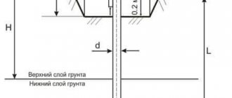
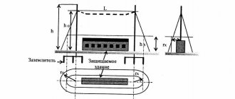
| RD 34.21.122-87 | Instructions for the installation of lightning protection of buildings and structures | |
| RD 34.20.182-90 | Guidelines for standard protection against vibration and suboscillations of wires and lightning protection cables of overhead power lines with voltage 35-750 kV |
INSTALLATION OF METERS AND ELECTRICAL WIRING TO THEM
1.5.27. Meters must be located in dry rooms that are easily accessible for maintenance, in a place that is sufficiently free and not cramped for work, with a temperature in winter not lower than 0 degrees. C.
General industrial meters are not allowed to be installed in rooms where, due to production conditions, the temperature can often exceed +40 degrees. C, as well as in rooms with aggressive environments.
It is allowed to place meters in unheated rooms and corridors of switchgears of power plants and substations, as well as in outdoor cabinets. In this case, provision should be made for their stationary insulation for the winter through insulating cabinets, hoods with heating of the air inside them with an electric lamp or heating element to ensure a positive temperature inside the hood, but not higher than +20 degrees. C.
1.5.28. Meters designed to account for electricity generated by power plant generators should be installed in rooms with an average ambient temperature of +15 - +25 degrees. C. In the absence of such premises, it is recommended that meters be placed in special cabinets, where the specified temperature must be maintained throughout the year.
1.5.29. Meters must be installed in cabinets, chambers of complete switchgears (KRU, KRUN), on panels, switchboards, in niches, on walls with a rigid structure.
It is allowed to mount meters on wooden, plastic or metal panels.
The height from the floor to the meter terminal box must be within 0.8 - 1.7 m. A height of less than 0.8 m is allowed, but not less than 0.4 m.
1.5.30. In places where there is a danger of mechanical damage to meters or their contamination, or in places accessible to unauthorized persons (passages, staircases, etc.), a locked cabinet with a window at dial level should be provided for meters. Similar cabinets should also be installed to co-locate meters and current transformers when performing metering on the low voltage side (at the consumer input).
1.5.31. Designs and sizes of cabinets, niches, panels, etc. should provide convenient access to the terminals of meters and current transformers. In addition, it must be possible to conveniently replace the meter and install it with a slope of no more than 1 degree. The design of its fastening must ensure the possibility of installing and removing the meter from the front side.
1.5.32. Electrical wiring to meters must meet the requirements given in Chapter. 2.1 and 3.4.
1.5.33. The presence of rations in the electrical wiring to the settlement meters is not allowed.
1.5.34. The cross-sections of wires and cables connected to meters must be taken in accordance with 3.4.4 (see also 1.5.19).
1.5.35. When installing electrical wiring to connect direct-connection meters, it is necessary to leave the ends of the wires with a length of at least 120 mm near the meters. The insulation or sheath of the neutral wire at a length of 100 mm in front of the meter must have a distinctive color.
1.5.36. For safe installation and replacement of meters in networks with voltages up to 380 V, it must be possible to turn off the meter by switching devices or fuses installed before it at a distance of no more than 10 m. Voltage relief must be provided from all phases connected to the meter.
Current transformers used to connect meters for voltages up to 380 V must be installed after switching devices in the direction of power flow.
1.5.37. Grounding (grounding) of meters and current transformers must be carried out in accordance with the requirements of Chapter. 1.7. In this case, the grounding and neutral protective conductors from meters and current transformers with voltages up to 1 kV to the nearest terminal assembly must be copper.
1.5.38. If there are several connections at the facility with separate electricity metering, the meter panels must contain inscriptions with the names of the connections.