Basic documents
Electrical installation rules apply to both government agencies and private developers.
In accordance with their provisions, the initial stage of work should be a well-designed wiring diagram in an apartment in an apartment building. The paper must be approved by the management company that issues the Technical Specifications. The standards for laying electrical wiring in residential premises are regulated by the following acts:
- Rules for electrical installations (PUE) - planning and installation, connections and switching, use of materials.
- GOST 31565-2012 - fire safety, fire prevention.
- GOST 50571.15-97 - rules for laying lines, installation methods on various surfaces.
- SP 256.1325800.2016 - grounding and safety, insulation and dimensions.
- SNiP 31-110-2003 - placement of devices, distance and installation locations.
Violation of the rules for laying wiring in an apartment entails administrative and financial liability.
Installation of hidden electrical wiring
Hidden electrical wiring can be laid in walls, on the ceiling and under the floor. Here you need to be prepared for severe contamination of the apartment due to the cutting of grooves and the dismantling of part of the floor covering.
Laying cables in walls
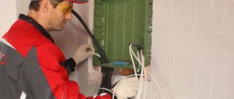
The most common method is to lay the cable in grooves cut into the walls. Work begins with marking the entire room. An exact copy of the completed wiring diagram is transferred to the walls and ceiling. It is convenient to cut the grooves with a wall chaser, but if you don’t have one, a grinder or hammer drill will do. There are no special requirements for the size of the grooves. It is necessary to ensure that the cable or corrugated sleeve fits freely inside, provided that they are covered with a 10 mm layer of plaster on top.
Inside the grooves, the cable is fastened every 500 mm. Many people do this with a simple gypsum solution, applying it at a certain distance. It will be more reliable to secure the wiring using dowels and clamps. Socket boxes are installed at connection points for sockets and switches, and distribution boxes are attached to connect branches. The free ends of the wire are led into socket boxes and distribution boxes, where the final connections of all contacts with terminal blocks into the general circuit take place.
The last thing to do is to connect the input cable inside the electrical panel. After this, voltage is applied to the network and, if everything works properly, you can begin sealing the grooves with plaster. Naturally, filling the grooves and all other similar work is carried out with the electricity turned off.
Cable laying under the floor
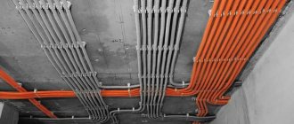
A more economical option is to lay the main line under the floors. This is easier to do when there is no floor covering yet. Otherwise, some part of it will have to be dismantled. The essence of the method is to lay hoses made of corrugated or ordinary pipes under the floor for each cable separately. The wire must penetrate freely inside the sleeve so that it can be replaced in the future without dismantling the floor covering.
The distribution panel is mounted on the wall. An input cable is connected to it from under the floor. Further connections to the machines will take place inside the panel. At the points where branches exit to sockets, switches and lighting devices, cable outlets 200 mm long are left from under the floors. Distribution boxes are installed here. All further connections occur in the same way as when laying the cable in the walls.
Ceiling cable routing
Things are simpler in panel houses. Many electricians lay cables inside the voids of interfloor slabs. Most often, room lighting lines are placed here. To avoid cutting grooves, a branch from the wall is pulled through the void of the slab and the wire is released from a drilled hole in the center of the ceiling to connect the lighting fixture.
Inside the ceiling, you can organize a common line, then only branches for sockets and switches will go to the walls. At the places where the cable turns and where the wires are connected in the junction box, an outlet of a maximum of 150 mm from the ceiling is made at a right angle.
Laying low-current cables
The rules for installing low-current networks include:
- The minimum space between adjacent low-current and high-current flows should be 0.5 m, but when overlapping, an angle of 90º is required
- It is forbidden to bring threads of low-current networks into the riser where electrical wires are located.
- It is forbidden to combine wires. Use only whole coils of wire
- The distribution box must be fixed to the wall, but not under or above the openings
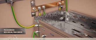
- Be sure to ground the bus or any copper conductor
- All boxes and blocks are filled to a maximum of half
Low-current networks include telephone, computer, and television networks.
To build such networks, different wires are needed depending on the purpose. For example, a computer network requires the use of copper cables; a telephone circuit requires category 3 wiring. Where to lay such networks:
When drawing wire lines, the possibility of risky mechanical overloads occurring in the working procedure is eliminated. They are laid in case of ground movements or deformation under the influence of temperatures or lighting, with an average spatial margin. Indoors this is done using the wave method in trays using cable slacks.
It is PROHIBITED to lay the spare length of wiring in rings, remember about induction. The cable, which is laid on walls or other flat surfaces horizontally, is secured at the end points, at the bends of the cable. Fixed with couplings and rubber strips for unarmored types.
Installation consists of two phases:
- Attach cable retaining structures
- Lay and connect to electrical equipment outlets
After removing the drum body, inspect its outer turns. If they are damaged, they are cut out and the insulating shell is checked with a voltage load. Paper insulation is examined for dryness. After such a check, sealed caps are placed on the ends.
General requirements
These requirements relate to the placement of wiring elements: meters, distribution boxes, sockets, switches and the placement of electrical wires.
Branching boxes, switches and sockets, electric meters are placed in places accessible for their maintenance (all current-carrying parts are covered). It is advisable to place switches in each room on one side of the door. Placement height – 1.5 meters from the level of the finished floor (floor covering)
Please note: when opening the door to the room, the switch must remain within reach. Sockets are mounted at a height of 0.5 - 0.8 m from the finished floor level. Their locations are determined by the planned arrangement of electrical equipment. There are also requirements for the number of sockets in an apartment: according to fire safety rules, they are installed at least one per six square meters
In the kitchen, regardless of its size, at least three of them must be installed. It is prohibited to install sockets in wet rooms - toilets and bathrooms. But there is one caveat here: to connect hair dryers and electric shavers, it is allowed to install sockets in bathrooms that are powered by double-insulated isolation transformers. It is not allowed to install sockets closer than half a meter from grounded radiators, gas stoves, steel pipelines and other metal devices. It is advisable to install sockets on the interior partition at one point on each side of the partition. In this case, they are connected in parallel through a through hole in the wall. All branches and connections of electrical wires in the apartment are made only in branch and junction boxes.
To avoid problems with damage to the electrical wiring during future repairs, wires should be laid only horizontally and vertically. Moreover, it is necessary to store the network laying plan. There are generally accepted standards for the placement of wires:
- horizontal sections are placed at a distance of 50 - 100 mm from beams and cornices and 150 mm from the ceiling and plinth (in the latter case, a distance of 200 mm is allowed);
- vertically located sections of the electrical network must be separated from the corners of the room and door and window openings by at least 100 mm. In this case, contact of the wire with the metal structures of the building (if any) is not allowed;
- if heating or hot water pipes are located near the wiring, it must be protected with asbestos gaskets. Another acceptable option is to use a wire with a thermal protective coating;
- if the wire is placed parallel to a gas pipe (or a pipeline with any other flammable substance), the distance between them must be at least 0.4 meters;
- It is prohibited to lay electrical wires in bundles in the apartment. It is also unacceptable to place them with a gap of less than 3 mm.
Diagram of correct electrical wiring in the house
The cores of the grounding and grounding wires are connected to each other by welding. Electrical devices to be protected are connected to the protective conductors using bolted connections.
To zero stationary electric stoves, a separate conductor is laid from the apartment meter. Its cross-section must be equal to the cross-section of the phase wire. This conductor is connected in front of the electric meter to the protective conductor of the power supply network. Grounding and neutral conductors should not have switches or fuses. This rule must be observed, otherwise, at the moment the protection is triggered, all household appliances will be exposed to the dangerous potential of the network.
All of the above requirements relate to the field of electrical safety.
Advantages of corrugation
The corrugation, which is used when installing in a screed, must be rigid or heavy, as it is also called.
It has almost the same appearance as a light PVC corrugated tube. However, the price for these products differs several times! As an alternative, many use orange or black HDPE corrugation. Three types of corrugated tubes and their characteristics PVC, HDPE, PP:
PVCHPNDPP
PP
However, do not forget that corrugated HDPE is flammable! Although the majority here are reassured by the moment of its installation on a concrete slab, and even a screed poured on top.
When using cheap PVC, during work, you will step on it more than once and push it with your own weight. At the same time, do not forget about careless handling of the stepladder and falling of heavy objects. All this can easily damage the cable insulation.
Anyone who dares to lay a cable in a screed without protection, that is, without corrugation, may face serious problems in the future. Unfortunately, the screed sometimes cracks, and along with them the wire will break.
By the way, regarding the myths about the replacement of wiring laid in corrugation, you can read in detail in the article “Installing cables in corrugation - errors and misconceptions.”
The only full-fledged replacement option can only be when laying a wide plastic cable channel or pipes into the wall.
This is often done on the wall where the TV will be hung. And then, in this case, completely different cables are used.
When installing on the floor, it is advisable to place the entire cable at a distance from the edge of the wall (approximately 30cm). There is no need to make connections close to it.
When installing baseboards, bar counters or other furniture, the cable can easily be pierced and damaged.
As for junction boxes, the best option would be to install all connections in the socket boxes. That is, where switches and sockets are installed, recessed socket boxes are used and all switching is performed inside them. If you need to audit contacts or reconnect something, there will be no problems with this.
The mechanism of the switch or socket itself is removed, the wires are pulled out from there and all the work is carried out. Then everything is put together in reverse order.
In this case, you do not need to dismantle and then re-stretch the suspended ceiling, as is the case with wiring along the top.
Installation requirements depending on the type of gasket
Correct installation involves not only compliance with general rules: for each type of electrical installation in an apartment, special requirements have been developed.
Open gasket
The easiest way is an open gasket. It doesn’t look very nice, of course, but there’s no need to trench the walls for wires. It is difficult to imagine such a method in an apartment, but in the utility rooms of country houses such a picture is not uncommon. But even such a primitive installation method has its own requirements:
- To perform electrical wiring in an open manner, flat wires АПРВ, АПР or АППВ are used. If the walls of the room are flammable (for example, made of wood), asbestos sheets with a thickness of at least 3 mm are laid between the wires and the base. The distance from the wire to the edge of the sheet is over 5 mm. The asbestos gasket is secured to the wall with nails in increments of 200 to 250 mm in a checkerboard pattern. For several groups of wires, it is allowed to use one common asbestos gasket (the distance between adjacent wires must be 5 mm or more).
- The wire is attached to the wall with a tin strip through a cardboard spacer. Moreover, a special electrical insulating cardboard is used for this purpose. The width and length of the gasket should exceed the similar dimensions of the tin bracket by several millimeters. The wire should be held tightly enough by the fastening element.
- Inside the junction box, the insulated ends of the wires must not be allowed to touch each other.
- Before entering the box, the wires are attached to the wall. The distance from the box body to the fastening element is 50 mm.
When wiring in an open way, sockets and switches are mounted on special socket boxes: plastic or wooden. Their diameter exceeds the similar size of rosettes by 8 - 10 millimeters.
Closed type
The safest way to install an internal electrical network is closed. The wires in this case are located inside a non-flammable material. They are inaccessible to accidental mechanical damage, do not oxidize and do not threaten the apartment with fire.
Concealed electrical wiring in the apartment
- If the walls of the house are built of wood, then closed wiring, like open wiring, is carried out on asbestos sheets. These requirements do not apply if the house is built of brick or reinforced concrete.
- Crossing flat wires is not allowed. If this is unavoidable, the intersection should be reinforced with insulating tape (3 - 4 layers per wire).
- The wires are secured in the grooves using alabaster. Special plastic clamps are often used. When wiring is closed, it is not permissible to use nails as fasteners.
- Branches and connections of wires are made by welding, crimping or soldering. These operations can be performed using special clamps in the space of branch boxes.
- If the walls in the apartment are covered with plasterboard, the electrical wiring fits perfectly under its layer and does not require cutting grooves in the base. Several holes of fairly large diameter are drilled in the plasterboard sheets - from 30 to 40 mm in the direction of the wiring route. Through these holes you can push a wire loop, with the help of which the wires are pulled in the desired direction. However, this is only relevant when the wiring is replaced in an already finished room. If the drywall has not yet been installed, it is easier to first carry out the electrical wiring and then sheathe the walls.
Combined method
The installation of electrical wires for the internal network in an apartment can also be carried out in a combined way using cable channels. This method is a cross between open and closed types of wiring installation. The cable duct can be made of non-flammable plastic, aluminum alloy or galvanized steel. It is easy to install, but in this case there are some requirements, if you violate them, you can doom yourself to endless alterations:
The first step is to choose the right type of box. There are several options for cable channels on sale. These include wall-mounted models, floor skirting boards, ceiling-type modifications, etc. The most common (and most practical) option is a wall-mounted cable channel made of plastic.
Cable protection materials
Protection of cable lines from mechanical damage can be done using the following types of materials:
- reinforced concrete slabs laid on top of the cable line backfill;
- solid ceramic brick;
- special boxes and pipes;
- protective and signal tapes made of high-strength polyethylene with a thickness of 3.5-5 mm (it is possible to use fiberglass reinforcement of the tape), with a bright, clearly visible warning inscription applied to the surface;
- protective and signal sheets made of polymer material.
Most often, protection of cables laid in the ground is carried out using reinforced concrete slabs, solid bricks and protective signal tapes.
Basic documents
The rules for installing electrical wiring are described in SNiP - these are norms and recommendations that help to safely conduct electrical wiring during construction or repair. Since 2010, all building codes have been recognized as a set of rules. More recently, SP 256.1325800.2016 was issued, which describes the requirements for power supply, grounding, and installation of electrical wiring in apartments, private houses and public premises. This is an updated version, but you can use earlier ones by first reading the update points.
In turn, SNiPs must comply with the Electrical Installation Rules (abbreviated PUE) and fire safety rules.
In addition, there are various GOSTs that describe the standards for grounding devices, cables, and other important elements of the electrical network. Thus, GOST 31565-2012 regulates the installation of cable products from the point of view of fire safety. And GOST 50571.15-97 is used for proper cable installation. Chapter 5 is used, which describes the electrical wiring requirements. An experienced electrician knows the basic safety rules and standards, and will always be able to carry out high-quality installation of electrical wiring.
Main points of requirements and rules
Table of cable cross-sections by power
Rules for laying electrical wiring cover a wide range of aspects of installation, from the selection of materials to the procedure for putting the structure into operation.
Minimum cross-section of cable cores:
- introductory - 4 mm;
- sockets - 2.5 mm;
- lighting group - 1 mm.
Number of conductor cores:
- single-phase line - 2;
- single-phase network with grounding - 3;
- two-phase supply - 3;
- two-phase network with grounding - 4.
Placing sockets, switches and electrical wiring at a distance from surfaces and objects:
- floor - 30-120 cm;
- panel joints - 20 cm;
- window and door openings - 10 cm;
- sewer and water pipes - 30 cm;
- sinks, bathtubs - 50 cm;
- heating devices - 20 cm;
- electric stoves - 15 cm;
- gas lines - 40 cm.
Types of wiring:
- with insulation of one or several colors;
- copper and aluminum;
- with regular and non-flammable coating.
Circuit breakers that are installed in the electrical panel:
- batch type;
- relay;
- fusible;
- electronic.
Line layout diagrams:
- sequential;
- parallel;
- combined.
Requirements for the installation of electrical wiring apply to residential and auxiliary premises, including loggias, balconies and vestibules.
General requirements
Requirements for choosing the cross-section of wires and cables
When choosing the cross-section of wires and cables in the wiring, you should proceed from the data in the table given in Table No. 1. When working with it, you need to consider the following points:
- the table provides average data, which in each specific case is determined by the power in the load and may have different values;
- when choosing the type and cross-section of wires, the conditions for their installation, determined by the safety category (group) of the serviced facility, must be taken into account;
- in addition, in some cases, such a choice is subject to special requirements regulated by fire safety standards (for electrical wiring in a wooden house, in particular).
Table 1. Value of cross-sections of current-carrying conductors
Let's look at each of these points in more detail.
The selection of specific values of permissible wire cross-sections must be made taking into account the currents acting in individual linear wiring circuits and determined in accordance with the power of the equipment connected to them (see table No. 2). To make it easier to select and calculate this parameter, experts advise that before installation, prepare a wiring diagram indicating the load currents of individual consuming devices (the current load in a circuit is determined as the result of dividing the power in the load by the voltage acting in it). All electrical parameter values necessary for such calculation can be found in the documentation for the connected equipment.
As for the dependence of the type of wires used on the conditions of their installation, before considering it, you should familiarize yourself with the classification of the latter according to the degree of danger. According to this indicator, all residential and non-residential objects are divided into the following categories (there are nine in total):
- Dry (heated or unheated), in which the relative air humidity is less than 60% and the average temperature does not exceed 30°C. At the same time, they do not contain chemically active environments or accumulations of conductive dust. Living rooms in the house should also be included in this category.
- Dusty with a large amount of conductive dust, which can settle on wires and also penetrate into equipment and electrical installations. This category also includes warehouse areas with bulk materials stored on them.
- Humid (bathrooms, kitchens, unheated warehouses), in which strong humidification is created as a result of steam formation, but at the same time the relative air humidity does not exceed 60–75%.
- So-called “damp” buildings, where air humidity exceeds 75% for a long time (vegetable storage, for example).
- Particularly raw, in which the same indicator is close to 100%; At the same time, droplets of moisture settle on the ceiling, floor, walls and objects placed inside. This category includes sheds, greenhouses, greenhouses, utility and unheated buildings.
- Another danger group consists of premises with a chemically active or organically hazardous environment (chemical warehouses, fertilizer storage facilities, poultry houses and special areas for keeping animals).
- The seventh, eighth and ninth danger groups include especially hot, fire and explosive objects (baths, saunas, warehouses of flammable materials and ammunition, etc.).
The last group can also include all wooden buildings in which, during the electrical installation process, special measures must be taken to protect the structure from fire.
Table 2. Selection of cable cross-section depending on the load current
Wiring Requirements
Installation of electrical wiring is carried out in accordance with current regulations (see SNiP), regulating the procedure for laying cables and harnesses in specially designated places and channels. The following places for placing electrical wiring in the house can be used:
- walls and ceilings of living rooms;
- special niches in building structures;
- cable channels hidden in elements of decorative finishing (plinths, trim);
- special cable channels and ducts.
The rules for installing electrical wiring in a house allow the use of separate insulated conductors, for the installation of which the following are most often used:
- metal or plastic pipes;
- plastic boxes or corrugated sleeves;
- special decorative insulators.
In this case, it is prohibited to install individual wires in the following places:
- in a hidden form (in grooves under plaster, for example);
- in the voids of building structures of panel-type houses;
- in open form (on the surface of ceilings and walls, in trays, etc.).
Rules for laying cables in trays
When in industrial premises the number of wires and cables laid along common routes is very large, it is advisable to use cable routing on trays. Trays are intended for:
- open laying of cables in dry, damp and hot rooms;
- rooms with a chemically active environment;
- fire hazardous premises for laying wires and cables permitted for such premises;
- cable mezzanines and basements of electrical machine rooms;
- passages behind shields and panels of control stations and transitions between them;
- technical floors of buildings and structures.
This electricity drainage system is highly flexible and greatly simplifies installation and operation. Wiring in trays provides good cooling conditions for cables, provides greater savings and reduces the cost of work compared to other types of wiring.
The trays provide free access to the cables along their entire length. If necessary, the cables can be easily removed and replaced with others; at the same time, you can change their number, section, brand, as well as route.
When using trays, it is easier to carry out wiring on complex routes; it is possible to arrange a branch on any section of the tray line route.
Trays are made of steel profiles and strips. Two types of trays are used: welded (2, 2.5 and 3 m long, 400, 200, 100 and 50 mm wide) and made of perforated strips (2 m long, 50 and 105 mm wide). Both types of trays are equipped with connecting angles and bolts for connecting the trays into a main. Individual trays and tray lines can be positioned horizontally, vertically and obliquely.
Cables on trays should be laid in one row.
Unarmored cables with a voltage of up to 1 kV with a core cross-section of up to 25 mm2 can be laid in trays in multi-layers, in bundles and single-layers without gaps. The height of cable layers laid in multilayers should be no more than 150 mm. The height (diameter) of the beam should be no more than 100 mm. The distance between bundles of power cables must be at least 20 mm; The distance between bundles of control cables, as well as power and control cables, is not standardized.
Fastening of cables laid in trays on straight sections of the route is not required when installing trays horizontally; with any other arrangement of trays, the cables are attached to the trays at intervals of no more than 2 m.
Rules for installing electrical wiring
During renovations in an apartment or house, the question usually arises of how to properly replace electrical wiring. If you want to do this yourself, then you need to know all the intricacies of proper electrical wiring.
As with other types of work, electrical wiring installation begins with planning, which is based on the principles of convenience and safety. Basically, of course, in developing the plan, the emphasis is on safety, because electricity is such a thing where negligence is unacceptable.
The work must be done competently and accurately, which will save you from problems and protect your home. A clear plan must be followed at all stages of work.
Requirements for connecting wires
There are also some important requirements for connecting wires.
The connection of the wires must be done in places where there is no mechanical impact. The reliability of the connection insulation must correspond to the insulation of the entire wires.
When installing wires in walls, it is necessary to leave a margin of 5 cm, for cases of connecting sockets, switches and connections in junction boxes.
Wiring connections in pipes are not permitted.
To connect the wires, use non-flammable plastic boxes with free access.
Wiring requirements prohibit twisting of wires. The best connection option is considered to be Wago terminals, crimping with sleeves and welding. Connections between copper and aluminum are permitted only through terminal blocks.
Installation of wire in a screed
Well, at the last stage, let's look at the installation itself. It is not so complicated and can be done with your own hands, but we should pay attention to some nuances.
We make walls for embedded boxes
- First of all, we are building walls to install embedded parts for sockets, switches and wiring to them. After all, these devices cannot be placed close to the floor. In this case, the groove should be of such a depth that the wire fits in the corrugation, and then the putty layer should be at least 1 cm.
Pulling wires in a corrugated
- The next step is to lay the corrugation. It is better to lay the corrugation with the wires already stretched, although this can be done later. When laying corrugations, we try to eliminate their intersection and get rid of sharp corners. This will make it easier for you to change the wire if necessary.
We try to avoid intersection of corrugated hoses
- After this, we connect all electrical points. It is mandatory to check their functionality with voltage applied. Ideally, even turn on all electrical points for a day, and then see if we have heating anywhere.
We fix the corrugation to the floor
- If we used plastic corrugation, then we fix it to the floor. This is necessary in case it starts to float while pouring the screed. This practically does not happen with metal corrugation, but it is better to secure it in the same way as in the video.
- Well, at the very last stage we directly fill the floor. In this case, it is better to remove the voltage from all wires in this room. The screed must provide at least a 3 cm layer above the corrugation. The functionality of the network should be checked only after the concrete has completely dried, which is 15–30 days.
4.2.96
Doors from the switchgear must open towards other rooms or outwards and have self-locking locks that can be opened without a key from the switchgear side.
Doors between compartments of one switchgear or between adjacent rooms of two switchgears must have a device that locks the doors in the closed position and does not prevent the doors from opening in both directions.
Doors between rooms (compartments) of switchgears of different voltages must open towards the switchgear with the lowest voltage.
Locks in the doors of switchgear rooms of the same voltage must be opened with the same key; keys to the entrance doors of the switchgear and other premises should not fit the locks of the cells, as well as the locks of doors in the fences of electrical equipment.
The requirement to use self-locking locks does not apply to switchgear of urban and rural distribution electrical networks with a voltage of 10 kV and below.
Beginning of work
Before installing wiring in an apartment, it is necessary to draw up a schematic wiring plan with the location of all points: sockets, switches, junction boxes, lighting fixtures.
To draw up a wiring diagram in an apartment, you need a large-scale plan of the premises, since in this case it is easier to calculate the required length of the electrical cable. When drawing a diagram, you need to adhere to generally accepted standards for designating devices so that the drawing is understandable to any person performing the work.
The placement of sockets and switches may have several standards. According to one of them, sockets are placed at a height of 0.3-1 m from the floor level, and switches at a height of 0.8-1.5 m. These values are not critical and are selected for ease of use. One of the factors in choosing a location is the arrangement of furniture.
In any standard, it is necessary to adhere to the requirements of the PUE, according to which horizontally laid wires in walls must depart from the ceiling at a distance of 150-200 mm, and the distances from door and window openings must be at least 100 mm.
Wiring plan
The location of sockets and switches in bathrooms is specified separately. The distance from the switching equipment to conductive elements (sewage and water supply pipes) must be at least 600 mm and at least 130 cm from the floor level.
PUE chapter 2.1. ELECTRICAL WIRING
SCOPE, DEFINITIONS
2.1.1. This chapter of the Rules applies to electrical wiring of power, lighting and secondary circuits with voltage up to 1 kV alternating and direct current, carried out inside buildings and structures, on their external walls, on the territories of enterprises, institutions, microdistricts, courtyards, personal plots, on construction sites using insulated installation wires of all cross-sections, as well as unarmored power cables with rubber or plastic insulation in a metal, rubber or plastic sheath with a cross-section of phase conductors up to 16 mm2 (for a cross-section of more than 16 mm2 - see Chapter 2.3). Lines carried out by uninsulated wires indoors must meet the requirements given in Chapter. 2.2, outside buildings - in chap. 2.4. Branches from overhead lines to inputs (see 2.1.6 and 2.4.2), made using insulated or non-insulated wires, must be constructed in compliance with the requirements of Chapter. 2.4, and branches made using wires (cables) on a supporting cable - in accordance with the requirements of this chapter. Cable lines laid directly in the ground must meet the requirements given in Chapter. 2.3. Additional requirements for electrical wiring are given in Chapter. 1.5, 3.4, 5.4, 5.5 and in Sect. 7. 2.1.2. Electrical wiring is a set of wires and cables with their associated fasteners, supporting protective structures and parts installed in accordance with these Rules. 2.1.3. Cable, cord, protected wire, unprotected wire, cable and special wire - definitions according to GOST. 2.1.4. Electrical wiring is divided into the following types: 1. Open electrical wiring - laid along the surface of walls, ceilings, along trusses and other construction elements of buildings and structures, along supports, etc. For open electrical wiring, the following methods of laying wires and cables are used: directly on the surface of walls, ceilings, etc., on strings, cables, rollers, insulators, in pipes, boxes, flexible metal sleeves, on trays, in electrical skirting boards and platbands, free suspension, etc. Open electrical wiring can be stationary, mobile and portable. 2. Hidden electrical wiring - laid inside the structural elements of buildings and structures (in walls, floors, foundations, ceilings), as well as over ceilings in floor preparation, directly under a removable floor, etc. For hidden electrical wiring, the following methods of laying wires and cables are used : in pipes, flexible metal hoses, boxes, closed channels and voids of building structures, in plastered grooves, under plaster, as well as embedded in building structures during their manufacture. 2.1.5. External electrical wiring is electrical wiring laid along the outer walls of buildings and structures, under canopies, etc., as well as between buildings on supports (no more than four spans up to 25 m long each) outside streets, roads, etc. External electrical wiring can be open and hidden. 2.1.6. The input from an overhead power line is the electrical wiring that connects the branch from the overhead line with the internal electrical wiring, counting from insulators installed on the outer surface (wall, roof) of a building or structure to the terminals of the input device. 2.1.7. A string, as a load-bearing element of electrical wiring, is a steel wire stretched close to the surface of a wall, ceiling, etc., intended for attaching wires, cables or their bundles to it. 2.1.8. A strip, as a load-bearing element of electrical wiring, is a metal strip fixed close to the surface of a wall, ceiling, etc., intended for attaching wires, cables or their bundles to it. 2.1.9. A cable as a load-bearing element of electrical wiring is a steel wire or steel rope, stretched in the air, intended for hanging wires, cables or their bundles from them. 2.1.10. A box is a closed hollow structure of rectangular or other cross-section, intended for laying wires and cables in it. The box should serve as protection against mechanical damage to the wires and cables laid in it. Boxes can be blind or with openable lids, with solid or perforated walls and lids. Blind boxes should have only solid walls on all sides and no lids. The boxes can be used indoors and outdoors. 2.1.11. A tray is an open structure designed for laying wires and cables on it. The tray does not protect against external mechanical damage to the wires and cables laid on it. Trays must be made of fireproof materials. They can be solid, perforated or lattice. The trays can be used in indoor and outdoor installations. 2.1.12. An attic space is a non-production space above the top floor of a building, the ceiling of which is the roof of the building and which has load-bearing structures (roof, trusses, rafters, beams, etc.) made of combustible materials. Similar rooms and technical floors located directly above the roof, the ceilings and structures of which are made of fireproof materials, are not considered as attic spaces.
GENERAL REQUIREMENTS
2.1.13. Permissible long-term currents on wires and cables of electrical wiring must be taken in accordance with Ch. 1.3 taking into account the ambient temperature and installation method. 2.1.14. The cross-sections of current-carrying conductors of wires and cables in electrical wiring must be no less than those given in table. 2.1.1. The cross-sections of conductors for charging lighting fixtures must be taken according to 6.5.12-6.5.14. The cross-sections of grounding and neutral protective conductors must be selected in compliance with the requirements of Chapter. 1.7.
Table 2.1.1. The smallest cross-sections of current-carrying conductors of wires and cables in electrical wiring
Conductors Core cross-section, mm2 copper aluminum Cords for connecting household electrical receivers 0,35 — Cables for connecting portable and mobile power receivers in industrial installations 0,75 — Twisted two-core wires with stranded cores for stationary installation on rollers 1 — Unprotected insulated wires for fixed indoor electrical wiring: directly on the bases, on rollers, clicks and cables 1 2,5 on trays, in boxes (except for blind ones): for conductors connected to screw terminals 1 2 for conductors connected by soldering: single-wire 0,5 — stranded (flexible) 0,35 — on insulators 1,5 4 Unprotected insulated wires in external electrical wiring: on walls, structures or supports on insulators; 2,5 4 overhead line inputs under canopies on casters 1,5 2,5 Unprotected and protected insulated wires and cables in pipes, metal sleeves and blind boxes 1 2 Cables and protected insulated wires for stationary electrical wiring (without pipes, sleeves and blind boxes): for conductors connected to screw terminals 1 2 for conductors connected by soldering: single-wire 0,5 — stranded (flexible) 0,35 — Protected and unprotected wires and cables laid in closed channels or monolithically (in building structures or under plaster) 1 2 2.1.15. In steel and other mechanical strong pipes, hoses, boxes, trays and closed channels of building structures, joint laying of wires and cables is allowed (with the exception of mutually redundant ones): 1. All circuits of one unit. 2. Power and control circuits of several machines, panels, panels, consoles, etc., connected by the technological process. 3. Circuits powering a complex lamp. 4. Circuits of several groups of one type of lighting (working or emergency) with a total number of wires in the pipe no more than eight. 5. Lighting circuits up to 42 V with circuits above 42 V, provided that the wires of circuits up to 42 V are enclosed in a separate insulating pipe. 2.1.16. In one pipe, sleeve, box, bundle, closed channel of a building structure or on one tray, the joint installation of mutually redundant circuits, circuits of working and emergency evacuation lighting, as well as circuits up to 42 V with circuits above 42 V is prohibited (for an exception, see 2.1.15 , clause 5 and in 6.1.16, clause 1). The laying of these chains is allowed only in different compartments of boxes and trays that have solid longitudinal partitions with a fire resistance limit of at least 0.25 hours made of fireproof material. It is allowed to lay emergency (evacuation) and working lighting circuits on different outer sides of the profile (channel, angle, etc.). 2.1.17. In cable structures, industrial premises and electrical premises, for electrical wiring, wires and cables with sheaths only made of fire-resistant or non-combustible materials should be used, and unprotected wires - with insulation only made of fire-resistant or non-combustible materials. 2.1.18. With alternating or rectified current, the laying of phase and neutral (or direct and return) conductors in steel pipes or insulating pipes with a steel sheath must be carried out in one common pipe. It is allowed to lay phase and neutral working (or direct and return) conductors in separate steel pipes or in insulating pipes with a steel sheath, if the long-term load current in the conductors does not exceed 25 A. 2.1.19. When laying wires and cables in pipes, blind boxes, flexible metal sleeves and closed channels, it must be possible to replace wires and cables. 2.1.20. Structural elements of buildings and structures, closed channels and voids of which are used for laying wires and cables, must be fireproof. 2.1.21. Connection, branching and termination of wire and cable cores must be carried out using crimping, welding, soldering or clamping (screw, bolt, etc.) in accordance with current instructions approved in the prescribed manner. 2.1.22. At the points of connection, branching and connection of wire or cable cores, a supply of wire (cable) must be provided, ensuring the possibility of re-connection, branching or connection. 2.1.23. Connections and branches of wires and cables must be accessible for inspection and repair. 2.1.24. At junctions and branches, wires and cables should not experience mechanical tension. 2.1.25. Places of connection and branching of conductors of wires and cables, as well as connecting and branch clamps, etc. must have insulation equivalent to the insulation of conductors of entire sections of these wires and cables. 2.1.26. Connection and branching of wires and cables, with the exception of wires laid on insulating supports, must be carried out in junction and branch boxes, in insulating housings of connecting and branch clamps, in special niches of building structures, inside the housings of electrical installation products, devices and machines. When laying on insulating supports, the connection or branch of the wires should be made directly at the insulator, the face or on them, as well as on the roller. 2.1.27. The design of junction and branch boxes and clamps must correspond to the laying methods and environmental conditions. 2.1.28. Connection and branch boxes and insulating housings of connecting and branch clamps should, as a rule, be made of fireproof or non-combustible materials. 2.1.29. Metal elements of electrical wiring (structures, boxes, trays, pipes, sleeves, boxes, brackets, etc.) must be protected from corrosion in accordance with environmental conditions. 2.1.30. Electrical wiring must be made taking into account possible movements at points of intersection with temperature and sedimentary seams.
shells of increased heat resistance. 2.1.43. In damp and especially damp rooms and outdoor installations, wire insulation and insulating supports, as well as supporting and load-bearing structures, pipes, boxes and trays must be moisture-resistant. 2.1.44. In dusty rooms, it is not recommended to use installation methods in which dust can accumulate on electrical wiring elements and make it difficult to remove. 2.1.45. In indoor and outdoor installations with a chemically active environment, all electrical wiring elements must be resistant to the environment or protected from its influence. 2.1.46. Wires and cables that have non-light-resistant outer insulation or sheath must be protected from exposure to direct rays. 2.1.47. In places where mechanical damage to electrical wiring is possible, openly laid wires and cables must be protected from them by their protective shells, and if such shells are absent or are not sufficiently resistant to mechanical stress, by pipes, ducts, fences or the use of hidden electrical wiring. 2.1.48. Wires and cables should only be used in those areas specified in the standards and specifications for cables (wires). 2.1.49. For stationary electrical wiring, predominantly wires and cables with aluminum conductors should be used. For exceptions, see 2.1.70, 3.4.3, 3.4.12, 5.5.6, 6.5.12-6.5.14, 7.2.53 and 7.3.93.
Table 2.1.2. Selecting types of electrical wiring, installation methods and wires and cables
Environmental conditions Type of electrical wiring and installation method Wires and cables Open wiring Dry and wet areas On roller skates and skating Unprotected solid wires Dry rooms Same Twisted two-core wires Premises of all types and outdoor installations On insulators, as well as on rollers intended for use in damp places. In outdoor installations, rollers for damp places (large sizes) may only be used in places where there is no possibility of direct rain or snow coming into contact with the electrical wiring (under canopies) Unprotected solid wires Outdoor installations Directly on the surface of walls, ceilings and on strings, strips and other supporting structures Non-metallic and metallic sheathed cable Premises of all types Same Unprotected and protected single and multi-core wires. Cables with non-metallic and metallic sheaths Premises of all types and outdoor installations On trays and in boxes with openable lids Same All types of premises and outdoor installations (only special wires with a supporting cable for outdoor installations or cables) On ropes Special wires with a supporting cable. Unprotected and protected single and multi-core wires. Cables with non-metallic and metallic sheaths Hidden electrical wiring Premises of all types and outdoor installations In non-metallic pipes made of combustible materials (non-self-extinguishing polyethylene, etc.). In closed channels of building structures. Under the plaster Unprotected and protected, single- and multi-core wires. Non-metallic sheathed cables Exceptions: 1. The use of insulating pipes with a metal sheath in damp, especially damp rooms and outdoor installations is prohibited. 2. It is prohibited to use steel pipes and steel blind boxes with a wall thickness of 2 mm or less in damp, especially damp rooms and outdoor installations. Dry, wet and damp areas Embedded in building structures during their manufacture Unprotected wires Open and hidden electrical wiring Premises of all types and outdoor installations In metal flexible sleeves. In steel pipes (ordinary and thin-walled) and blind steel boxes. In non-metallic pipes and non-metallic blind boxes made of fire-resistant materials. In insulating pipes with metal sheath Unprotected and protected single and multi-core wires. Non-metallic sheathed cables Exceptions: 1. The use of insulating pipes with a metal sheath in damp, especially damp rooms and outdoor installations is prohibited. 2. It is prohibited to use steel pipes and steel blind boxes with a wall thickness of 2 mm or less in damp, especially damp rooms and outdoor installations. Table 2.1.3. Selecting types of electrical wiring and methods of laying wires and cables according to fire safety conditions
Type of electrical wiring and method of laying on foundations and structures Wires and cables from combustible materials made of fireproof or fire-resistant materials Open wiring On rollers, insulators or lined with fireproof materials1 Directly Unprotected wires; protected wires and cables sheathed in combustible materials Directly » Protected wires and cables sheathed from fireproof and fire-resistant materials In pipes and boxes made of fireproof materials In pipes and boxes made of fire-resistant and non-combustible materials Unprotected and protected wires and cables sheathed from combustible, non-combustible materials Hidden electrical wiring With a lining of fireproof materials1 and subsequent plastering or protection on all sides with a continuous layer of other fireproof materials Directly Unprotected wires; protected wires and cables sheathed in combustible materials Lined with fireproof materials1 » Protected wires and cables sheathed in flame retardant materials Directly » The same from fireproof In pipes and ducts made of non-combustible materials - with lining under the pipes and ducts of non-combustible materials1 and subsequent plastering2 In pipes and ducts: from combustible materials - monolithically, in grooves, etc., in a continuous layer of non-combustible materials3 Unprotected wires and cables sheathed in combustible, non-combustible and non-combustible materials The same from fireproof materials - directly The same from flame retardant and non-combustible materials - directly ______________ 1 A lining made of fireproof materials must protrude from each side of the wire, cable, pipe or box by at least 10 mm. 2 Plastering of the pipe is carried out with a continuous layer of plaster, alabaster, etc., at least 10 mm thick above the pipe. 3 A continuous layer of fireproof material around the pipe (box) can be a layer of plaster, alabaster, cement mortar or concrete with a thickness of at least 10 mm. The use of wires and cables with aluminum conductors for connection to electrical devices installed directly on vibration-isolating supports is not allowed. In museums, art galleries, libraries, archives and other storage facilities of national importance, wires and cables should only be used with copper conductors. 2.1.50. To power portable and mobile electrical receivers, cords and flexible cables with copper conductors should be used, specifically designed for this purpose, taking into account possible mechanical stress. All conductors of the specified conductors, including the grounding conductor, must be in a common sheath, braid or have common insulation. For mechanisms that have limited movement (cranes, mobile saws, gate mechanisms, etc.), conductor structures should be used that protect the cores of wires and cables from breaking (for example, flexible cable loops, carriages for movable suspension of flexible cables). 2.1.51. If there are oils and emulsions in the places where the wires are laid, you should use wires with oil-resistant insulation or protect the wires from their influence.
OPEN ELECTRICAL CIRCUITING INDOOR PREMISES
2.1.52. Open laying of unprotected insulated wires directly on bases, on rollers, insulators, on cables and trays should be carried out: 1. At voltages above 42 V in rooms without increased danger and at voltages up to 42 V in any rooms - at a height of at least 2 m from floor level or service platform. 2. For voltages above 42 V in high-risk and especially dangerous areas - at a height of at least 2.5 m from the floor or service area. These requirements do not apply to descents to switches, sockets, starting devices, panels, lamps installed on the wall. In industrial premises, descents of unprotected wires to switches, sockets, devices, panels, etc. must be protected from mechanical influences to a height of at least 1.5 m from the floor or service area. In domestic premises of industrial enterprises, in residential and public buildings, the specified slopes may not be protected from mechanical influences. In rooms accessible only to specially trained personnel, the height of openly laid unprotected insulated wires is not standardized. 2.1.53. In crane spans, unprotected insulated wires should be laid at a height of at least 2.5 m from the level of the crane trolley platform (if the platform is located above the crane bridge deck) or from the crane bridge deck (if the deck is located above the trolley platform). If this is not possible, then protective devices must be installed to protect personnel on the trolley and crane bridge from accidentally touching the wires. A protective device must be installed along the entire length of the wires or on the crane bridge itself within the location of the wires. 2.1.54. The height of open laying of protected insulated wires, cables, as well as wires and cables in pipes, boxes with a degree of protection not lower than IP20, in flexible metal hoses from the level of the floor or service area is not standardized. 2.1.55. If unprotected insulated wires intersect with unprotected or protected insulated wires with a distance between the wires of less than 10 mm, then additional insulation must be applied to each unprotected wire at the intersection points. 2.1.56. When crossing unprotected and protected wires and cables with pipelines, the clear distance between them must be at least 50 mm, and with pipelines containing flammable or flammable liquids and gases - at least 100 mm. When the distance from wires and cables to pipelines is less than 250 mm, wires and cables must be additionally protected from mechanical damage for a length of at least 250 mm in each direction from the pipeline. When crossing hot pipelines, wires and cables must be protected from high temperatures or must be designed accordingly. 2.1.57. When laying parallel, the distance from wires and cables to pipelines must be at least 100 mm, and to pipelines with flammable or flammable liquids and gases - at least 400 mm. Wires and cables laid parallel to hot pipelines must be protected from high temperatures or must be designed accordingly. 2.1.58. In places where wires and cables pass through walls, interfloor ceilings or where they exit outside, it is necessary to ensure the possibility of changing electrical wiring. To do this, the passage must be made in a pipe, duct, opening, etc. In order to prevent the penetration and accumulation of water and the spread of fire in places of passage through walls, ceilings or exits to the outside, the gaps between wires, cables and the pipe (duct, opening) should be sealed etc.), as well as backup pipes (ducts, openings, etc.) with an easily removable mass from non-combustible material. The seal must allow replacement, additional installation of new wires and cables and ensure the fire resistance limit of the opening is not less than the fire resistance limit of the wall (floor). 2.1.59. When laying unprotected wires on insulating supports, the wires must be additionally insulated (for example, with an insulating pipe) in places where they pass through walls or ceilings. When these wires pass from one dry or wet room to another dry or wet room, all wires of one line can be laid in one insulating pipe. When passing wires from a dry or damp room to a damp one, from one damp room to another damp one, or when wires exit a room outside, each wire must be laid in a separate insulating pipe. When leaving a dry or damp room into a damp or outside building, wire connections must be made in a dry or damp room. 2.1.60. On trays, supporting surfaces, cables, strings, strips and other supporting structures, it is allowed to lay wires and cables close to each other in bundles (groups) of various shapes (for example, round, rectangular in several layers). The wires and cables of each bundle must be fastened together. 2.1.61. In boxes, wires and cables can be laid in multilayers with an ordered and random (scattered) mutual arrangement. The sum of the cross-sections of wires and cables, calculated by their outer diameters, including insulation and outer sheaths, should not exceed: for blind boxes, 35% of the clear cross-section of the box; for boxes with openable lids 40%. 2.1.62. Permissible long-term currents on wires and cables laid in bundles (groups) or multilayered must be taken into account reducing factors that take into account the number and location of conductors (cores) in the bundle, the number and relative position of bundles (layers), as well as the presence of unloaded conductors. 2.1.63. Pipes, ducts and flexible metal hoses of electrical wiring must be laid so that moisture cannot accumulate in them, including from condensation of vapors contained in the air. 2.1.64. In dry, dust-free rooms, in which there are no vapors and gases that negatively affect the insulation and sheath of wires and cables, it is allowed to connect pipes, ducts and flexible metal hoses without sealing. The connection of pipes, ducts and flexible metal hoses with each other, as well as with ducts, electrical equipment housings, etc. must be made: in rooms that contain vapors or gases that adversely affect the insulation or sheathing of wires and cables, in outdoor installations and in places where oil, water or emulsion can get into pipes, boxes and hoses - with a seal; boxes in these cases must have solid walls and sealed solid covers or blind ones, detachable boxes must have seals at the joint points, and flexible metal hoses must be sealed; in dusty rooms - with sealing of connections and branches of pipes, hoses and boxes to protect against dust. 2.1.65. The connection of steel pipes and boxes used as grounding or neutral protective conductors must comply with the requirements given in this chapter and Ch. 1.7.
HIDDEN ELECTRICAL WIRING INSIDE PREMISES
2.1.66. Hidden electrical wiring in pipes, ducts and flexible metal hoses must be made in compliance with the requirements given in 2.1.63-2.1.65, and in all cases with a seal. Concealed electrical wiring boxes must be solid. 2.1.67. Electrical wiring in ventilation ducts and shafts is prohibited. It is allowed to cross these channels and shafts with single wires and cables enclosed in steel pipes. 2.1.68. The laying of wires and cables behind suspended ceilings should be carried out in accordance with the requirements of this chapter and Chapter. 7.1.
ELECTRICAL WIRING IN THE ATTIC
2.1.69. The following types of electrical wiring can be used in attic spaces: open; wires and cables laid in pipes, as well as protected wires and cables in sheaths made of fireproof or fire-resistant materials - at any height; unprotected insulated single-core wires on rollers or insulators (in attics of industrial buildings - only on insulators) - at a height of at least 2.5 m; when the height of the wires is less than 2.5 m, they must be protected from touch and mechanical damage; hidden: in walls and ceilings made of fireproof materials - at any height. 2.1.70. Open electrical wiring in the attic must be carried out using wires and cables with copper conductors. Wires and cables with aluminum conductors are allowed in the attic of: buildings with fireproof floors - when laid openly in steel pipes or hidden in fireproof walls and ceilings; industrial buildings for agricultural purposes with combustible floors - when they are laid openly in steel pipes, excluding the penetration of dust into the pipes and connecting (branch) boxes; In this case, threaded connections must be used. 2.1.71. The connection and branching of copper or aluminum conductors of wires and cables in the attic must be carried out in metal junction (branch) boxes by welding, crimping or using clamps corresponding to the material, cross-section and number of conductors. 2.1.72. Electrical wiring in the attic, made using steel pipes, must also meet the requirements given in 2.1.63-2.1.65. 2.1.73. Branches from lines laid in attics to electrical receivers installed outside attics are allowed provided that the lines and branches are laid openly in steel pipes or hidden in fireproof walls (floors). 2.1.74. Switching devices in circuits of lamps and other electrical receivers installed directly in attic spaces must be installed outside these rooms.
EXTERNAL ELECTRIC WIRING
2.1.75. Unprotected insulated wires of external electrical wiring must be located or fenced in such a way that they are inaccessible for touching from places where people may be frequently present (for example, a balcony, porch). From the indicated places, these wires, laid openly along the walls, must be located at a distance of at least m:
For horizontal installation: under a balcony, porch, and also above the roof of an industrial building. 2,5 above the window 0,5 under the balcony 1,0 under the window (from the window sill) 1,0 When laying vertically to the window 0,75 The same, but up to the balcony 1,0 From the earth 2,75 When hanging wires on supports near buildings, the distance from the wires to balconies and windows must be at least 1.5 m with a maximum deviation of the wires. External electrical wiring on the roofs of residential, public buildings and entertainment enterprises is not allowed, with the exception of inputs into buildings (enterprises) and branches to these inputs (see 2.1.79). Unprotected insulated wires of external electrical wiring should be considered as uninsulated with regard to touch. 2.1.76. The distances from wires crossing fire passages and paths for the transportation of goods to the surface of the earth (road) in the roadway must be at least 6 m, in the non-roadway - at least 3.5 m. 2.1.77. The distances between the wires should be: for a span of up to 6 m - at least 0.1 m, for a span of more than 6 m - at least 0.15 m. The distances from the wires to the walls and supporting structures must be at least 50 mm. 2.1.78. The laying of wires and cables for external electrical wiring in pipes, ducts and flexible metal sleeves must be carried out in accordance with the requirements given in 2.1.63-2.1.65, and in all cases with a seal. Laying wires in steel pipes and ducts in the ground outside buildings is not allowed. 2.1.79. Entries into buildings are recommended to be made through walls in insulating pipes so that water cannot accumulate in the passage and penetrate into the building. The distance from the wires in front of the input and the input wires to the ground surface must be at least 2.75 m (see also 2.4.37 and 2.4.56). The distance between the wires at the input insulators, as well as from the wires to the protruding parts of the building (roof overhangs, etc.) must be at least 0.2 m. Inputs can be made through roofs in steel pipes. In this case, the vertical distance from the branch wires to the input and from the input wires to the roof must be at least 2.5 m. For buildings of small height (trade pavilions, kiosks, container-type buildings, mobile booths, vans, etc.), on the roofs of which the presence of people is excluded, the clear distance from the branch wires to the input and the input wires to the roof is allowed to be at least 0.5 m. In this case, the distance from the wires to the ground surface must be at least 2.75 m.
Rules for introducing electricity into the house
For private households, such an issue as introducing electricity into the house is important. Usually it is carried out using a self-supporting SIP wire.
If the power line support is located less than 25 m from the house, additional poles for support will not be required.
The wire usually extends to an electrical panel with an RCD, circuit breakers and a connection to the ground loop located in it. The transition to home cable (for example, VVGng) usually occurs in another panel - with metering devices
Input requirements:
- when the wire length is more than 25 m, additional supports are required (you can install a shield on the pole closest to the house, and bury the ground loop in the ground nearby);
- the height of the wire stretched between the supports is at least 2 m above the ground;
- if the wire crosses building structures, it is mounted in a protective pipe;
- the minimum distance from the ground for the building connection point is 2.75 m;
- if the wire from the control panel to the house is planned to be laid underground, then it must be placed in a protective sheath and then in a ditch at least 0.7 m deep.
It is clear that when choosing an underground installation, the entry directly into the building must be provided during the construction process.
Types of cables used
Before laying the line, the type of low-current cable is selected - its functional purpose is taken into account. The brand is indicated in the wiring diagram. In the case of digital data transmission and broadcasting television signals, coaxial cable is used. Twisted pairs are used to transmit digital/analog signals, and stranded, shielded wires are used for discrete ones.
The laying of low-current cables in rooms is most often carried out in a hidden way - the boxes not only provide protection, but also improve aesthetics. If there is no risk of damage, the wires can be stretched along the walls without using a protective box (open method). Outdoor installation is carried out underground (the most protected, but quite labor-intensive method) or over the air (wires do not require trenching, but they are poorly protected from weather factors).
number of sockets on the cable 3x2.5
About serial connection. Nothing comes to mind except soldering several 12 V light bulbs in series to get the total. So in “Young Technician” they talked about making a Christmas tree garland with your own hands. In short, you need about 19 light bulbs, you can use car ones.
Just need to solder carefully so as not to melt the base and ruin the light bulb. If one burns out, the whole circuit will open and there will be no light. Tell me, is my concept about serial and parallel connections correct, or am I wrong about something? Perhaps the concepts are somewhat different among professional electricians? Yes, this can be any number of electrical points on the line.
Wire selection
For apartment electrical wiring, wires and cables with single- or multi-wire conductors, made of copper or aluminum, are used, taking into account that the maximum current load through them will not exceed the maximum permissible, determined by the installation method, material and cross-section of the conductors.
Although the rules allow the use of aluminum wires as electrical wiring, this is not recommended for the following reasons:
- Aluminum has lower permissible currents and higher ohmic resistance. Because of this, wires need a larger cross-section than copper ones;
- Such wires are less mechanically strong. In places of kinks or if the insulation is not properly stripped, the aluminum core breaks very easily;
- When installing electrical devices, sockets, switches, the aluminum wire in the terminals tends to “flow” over time, that is, change its shape. This leads to relaxation of the contact and an increase in contact resistance. Because of this, the terminals of the devices begin to overheat, which leads to even greater deformation of the aluminum conductors and, ultimately, to burnout at the point of contact;
- Soldering of aluminum wires is not possible;
- The biggest problems arise when it is necessary to connect copper and aluminum conductors.
The only advantage of aluminum wires is lower cost. The electrical wiring in older houses is mostly aluminum and requires complete replacement.
To conduct lighting circuits, a two-core wire is sufficient, but to connect sockets you need to use a special three-core cable, one of the wires of which is two-colored - yellow with a green stripe. This conductor is used to connect to the ground terminals in modern sockets. Modern lighting fixtures are often also equipped with terminals for connecting a ground wire.
Important! Never use the yellow-green wire to supply power to devices, regardless of whether it will be phase or neutral!
Grounding conductor
Among the many brands of cables for electrical wiring, the VVGng type cable is very popular. This type of cable is made with polyvinyl chloride overall insulation and each core individually. The cores can be single or multi-wire. The symbols “ng” indicate reduced flammability of the cable. An even better option is the VVGngls cable with reduced smoke emission, although it is somewhat more expensive, but if possible, it is better to purchase it.
4.2.91
The width of the service corridor for switchgear with withdrawable elements and package transformer substations should ensure ease of control, movement and reversal of equipment and its repair.
When installing switchgear and package transformer substations in separate rooms, the width of the service corridor should be determined based on the following requirements:
for single-row installation - the length of the largest of the switchgear trolleys (with all protruding parts) plus at least 0.6 m;
for a double-row installation - the length of the largest of the switchgear trolleys (with all protruding parts) plus at least 0.8 m.
If there is a corridor at the rear of the switchgear and package transformer substations for their inspection, its width must be at least 0.8 m; Individual local narrowings of no more than 0.2 m are allowed.
When installing switchgear and package transformer substations openly in production premises, the width of the free passage must be determined by the location of the production equipment, ensure the possibility of transporting the largest switchgear elements to the switchgear substations, and in any case it must be at least 1 m.
The height of the room must be no less than the height of the switchgear, package transformer substations, counting from busbar entries, jumpers or protruding parts of cabinets, plus 0.8 m to the ceiling or 0.3 m to the beams.
A lower room height is allowed if this ensures the convenience and safety of replacement, repair and adjustment of switchgear equipment, package transformer substations, busbar inputs and jumpers.
Rules for laying cables in cable tunnels
Cable tunnels (and collectors in which pipelines are also laid) are recommended to be built in cities and enterprises with densely built-up areas or when the territory is heavily saturated with underground utilities, as well as in the territories of large metallurgical, engineering and other enterprises. Cable tunnels are constructed, as a rule, with the number of cables being laid from 20. Tunnels usually serve as trunk lines.
Rectangular cable tunnels are designed for double-sided and single-sided cable laying and come in pass-through and semi-pass-through designs.
With a large number of cables, tunnels and rectangular-section collectors can be three-walled (double). In table 5.6 shows the main dimensions of rectangular tunnels.
The use of semi-through tunnels is allowed in places where underground communications interfere with the construction of a through tunnel; in this case, a semi-through tunnel is accepted with a length of no more than 15 m and for cables with a voltage of no higher than 10 kV.
The width of passages in cable tunnels and collectors must be at least 1 m, however, it is allowed to reduce the width of passages to 800 mm in sections no longer than 500 mm.
Extended cable tunnels and collectors are divided along their length by fire-resistant partitions into compartments no longer than 150 m with doors installed in them. The laying of cables in collectors and tunnels is calculated taking into account the possibility of additional cable laying in an amount of at least 15%.
When cable structures are installed on both sides, control cables should be placed, if possible, on the opposite side of the power cables. When structures are located on one side, control cables should be placed under power cables and separated by a horizontal partition.
Power cables with voltages up to 1 kV should be laid under cables with voltages above 1 kV and separated by a horizontal partition. It is recommended to lay different groups of cables (working and backup voltages above 1 kV) on different shelves separated by horizontal fireproof partitions. at least 8 mm as partitions .
The use of unarmored cables with a polyethylene sheath in cable tunnels is prohibited under fire safety conditions.
Cables laid horizontally along structures are rigidly fixed at end points, at route turns, on both sides of cable bends, at connecting and end couplings and terminations. Cables laid vertically along structures and walls are secured to each cable structure. At the points of attachment between unarmored cables with a lead or aluminum sheath, metal supporting structures and a metal bracket, gaskets made of elastic material (sheet rubber, sheet polyvinyl chloride) with a thickness of at least 2 mm must be laid, protecting the sheath from mechanical damage. Unarmored cables with a plastic sheath may be secured with brackets (clamps) without gaskets.
The metal armor of cables laid in tunnels must have an anti-corrosion coating.