In order for LED lamps to work as brightly and efficiently as possible, special modules are used - drivers. Anyone can assemble a driver circuit for LEDs on their own, if, of course, they have knowledge of electrical engineering. The purpose of the device is to convert the alternating voltage flowing in the network into direct (reduced) voltage. But before you start assembling, you need to decide what requirements are imposed on the device - analyze the characteristics and types of devices.
What are drivers for?
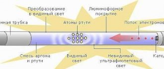
The main purpose of the drivers is to stabilize the current that passes through the LED. Moreover, it is necessary to take into account that the current strength that passes through the semiconductor crystal must be exactly the same as that of the LED according to the passport. This ensures stable lighting. The crystal in the LED will last much longer. To find out the voltage required to power the LEDs, you need to use the current-voltage characteristic. This is a graph showing the relationship between supply voltage and current.
If you plan to illuminate a residential or office space with LED lamps, then the driver must be powered from a household AC network with a voltage of 220 V. If LEDs are used in automobiles or motorcycles, you need to use drivers powered by a constant voltage, value 9-36 V. V In some cases (if the LED lamp is of low power and is powered from a 220 V network), it is possible to remove the LED driver circuit. If the device is powered from the network, it is enough to include a constant resistor in the circuit.
How does an LED lamp work?
A close acquaintance with the design of an LED lamp may be required only in one case - if it is necessary to repair or improve the light source.
Home craftsmen, having a set of elements on hand, can independently assemble an LED lamp, but a beginner cannot do this.
Considering that LED devices have become the basis of lighting systems for modern apartments, the ability to understand the structure of lamps and repair them can save a significant part of the family budget
But, having studied the circuit and having basic skills in working with electronics, even a beginner will be able to disassemble the lamp, replace broken parts, restoring the functionality of the device. To find detailed instructions on how to identify a breakdown and repair an LED lamp yourself, please follow this link.
Does it make sense to repair an LED lamp? Undoubtedly. Unlike analogues with incandescent filaments for 10 rubles apiece, LED devices are expensive.
Let’s assume that a GAUSS “pear” costs about 80 rubles, and a better alternative OSRAM costs 120 rubles. Replacing a capacitor, resistor or diode will cost less, and the life of the lamp can be extended by timely replacement.
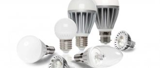
There are many modifications of LED lamps: candles, pears, balls, spotlights, capsules, strips, etc. They differ in shape, size and design. To clearly see the difference from an incandescent lamp, consider the common pear-shaped model.
Instead of a glass bulb there is a matte diffuser, the filament is replaced by “long-playing” diodes on the board, excess heat is removed by a radiator, and voltage stability is ensured by the driver
If you look away from the usual shape, you can notice only one familiar element - the base. The size range of socles remains the same, so they fit traditional sockets and do not require changing the electrical system. But this is where the similarities end: the internal structure of LED devices is much more complex than that of incandescent lamps.
LED lamps are not designed to operate directly from a 220 V network, so a driver is located inside the device, which is both a power supply and control unit. It consists of many small elements, the main task of which is to rectify the current and reduce the voltage.
Driver settings
Before purchasing a device or making it yourself, you need to familiarize yourself with what its main characteristics are:
- Rated current consumption.
- Power.
- Output voltage.
The voltage at the output of the converter directly depends on the chosen method of connecting the light source and the number of LEDs. The current has a direct relationship with the brightness and power of the elements.
The converter must provide a current at which the LEDs will operate at the same brightness. The PT4115 LED driver circuit is implemented quite simply - it is the most common voltage converter for use with LED elements. You can literally make a device based on it “on your knees.”
Basic circuits of pulse network adapters for charging phones
Schemes of pulse network adapters for charging phones
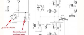
Most modern network chargers are assembled using a simple pulse circuit, using one high-voltage transistor (Fig. 1) according to a blocking generator circuit.
Unlike simpler circuits using a step-down 50 Hz transformer, the transformer for pulse converters of the same power is much smaller in size, which means the size, weight and price of the entire converter are smaller. In addition, pulse converters are safer - if in a conventional converter, when the power elements fail, the load receives a high unstabilized (and sometimes even alternating) voltage from the secondary winding of the transformer, then in case of any malfunction of the “pulse generator” (except for the failure of the reverse optocoupler) connection - but it is usually very well protected) there will be no voltage at the output at all.
Rice. 1 Simple pulse blocking oscillator circuit
A detailed description of the operating principle (with pictures) and calculation of the circuit elements of a high-voltage pulse converter (transformer, capacitors, etc.) can be read, for example, in “TEA152x Efficient Low Power Voltage supply” at https://www. nxp.com/acrobat/applicationnotes/AN00055.pdf (in English).
The alternating mains voltage is rectified by diode VD1 (although sometimes the generous Chinese install as many as four diodes in a bridge circuit), the current pulse when turned on is limited by resistor R1. Here it is advisable to install a resistor with a power of 0.25 W - then if overloaded, it will burn out, acting as a fuse.
The converter is assembled on transistor VT1 using a classic flyback circuit. Resistor R2 is needed to start generation when power is applied; in this circuit it is optional, but with it the converter works a little more stable. Generation is maintained thanks to capacitor C1, included in the PIC circuit on the winding, the generation frequency depends on its capacitance and the parameters of the transformer. When the transistor is unlocked, the voltage on the lower terminals of windings I and II in the diagram is negative, on the upper ones it is positive, the positive half-wave through capacitor C1 opens the transistor even more strongly, the voltage amplitude in the windings increases... That is, the transistor opens like an avalanche. After some time, as capacitor C1 charges, the base current begins to decrease, the transistor begins to close, the voltage at the upper terminal of winding II in the circuit begins to decrease, through capacitor C1 the base current decreases even more, and the transistor closes like an avalanche. Resistor R3 is necessary to limit the base current during circuit overloads and surges in the AC network.
At the same time, the amplitude of the self-induction EMF through the diode VD4 recharges the capacitor SZ - that is why the converter is called flyback. If you swap the terminals of winding III and recharge the capacitor SZ during the forward stroke, then the load on the transistor will sharply increase during the forward stroke (it may even burn out due to too much current), and during the reverse stroke the self-induction EMF will be unspent and will be released by collector junction of the transistor - that is, it can burn out from overvoltage. Therefore, when manufacturing the device, it is necessary to strictly observe the phasing of all windings (if you mix up the terminals of winding II, the generator simply will not start, since capacitor C1 will, on the contrary, disrupt generation and stabilize the circuit).
The output voltage of the device depends on the number of turns in windings II and III and on the stabilization voltage of the zener diode VD3. The output voltage is equal to the stabilization voltage only if the number of turns in windings II and III is the same, otherwise it will be different. During the reverse stroke, capacitor C2 is recharged through diode VD2, as soon as it is charged to approximately -5 V, the zener diode will begin to pass current, the negative voltage at the base of transistor VT1 will slightly reduce the amplitude of the pulses on the collector, and the output voltage will stabilize at a certain level. The stabilization accuracy of this circuit is not very high - the output voltage varies within 15...25% depending on the load current and the quality of the zener diode VD3. The circuit of a better (and more complex) converter is shown in Fig. 2
Rice. 2 Electrical circuit of a more complex converter
To rectify the input voltage, a diode bridge VD1 and a capacitor are used; the resistor must have a power of at least 0.5 W, otherwise at the moment of switching on, when charging capacitor C1, it may burn out. The capacitance of capacitor C1 in microfarads must be equal to the power of the device in watts.
The converter itself is assembled according to the already familiar circuit using transistor VT1. A current sensor on resistor R4 is included in the emitter circuit - as soon as the current flowing through the transistor becomes so large that the voltage drop across the resistor exceeds 1.5 V (with the resistance indicated on the diagram being 75 mA), transistor VT2 opens slightly through diode VD3 and limits the base current of transistor VT1 so that its collector current does not exceed the above 75 mA. Despite its simplicity, this protection circuit is quite effective, and the converter turns out to be almost eternal even with short circuits in the load.
To protect transistor VT1 from emissions of self-induction EMF, a smoothing circuit VD4-C5-R6 was added to the circuit. The VD4 diode must be high-frequency - ideally BYV26C, a little worse - UF4004-UF4007 or 1 N4936, 1 N4937. If there are no such diodes, it is better not to install a chain at all!
Capacitor C5 can be anything, but it must withstand a voltage of 250...350 V. Such a chain can be installed in all similar circuits (if it is not there), including the circuit in Fig. 1
- it will noticeably reduce the heating of the switch transistor housing and significantly “extend the life” of the entire converter.
The output voltage is stabilized using the zener diode DA1 located at the output of the device, galvanic isolation is provided by the optocoupler V01. The TL431 microcircuit can be replaced with any low-power zener diode, the output voltage is equal to its stabilization voltage plus 1.5 V (voltage drop across the optocoupler LED V01), a small resistance resistor R8 is added to protect the LED from overloads. As soon as the output voltage becomes slightly higher than expected, current will flow through the zener diode, the optocoupler LED will begin to glow, its phototransistor will open slightly, the positive voltage from capacitor C4 will slightly open transistor VT2, which will reduce the amplitude of the collector current of transistor VT1. The instability of the output voltage of this circuit is less than that of the previous one and does not exceed 10...20%; also, thanks to capacitor C1, there is practically no 50 Hz background at the output of the converter.
It is better to use an industrial transformer in these circuits, from any similar device.
But you can wind it yourself - for an output power of 5 W (1 A, 5 V), the primary winding should contain approximately 300 turns of wire with a diameter of 0.15 mm, winding II - 30 turns of the same wire, winding III - 20 turns of wire with a diameter of 0 .65 mm. Winding III must be very well insulated from the first two; it is advisable to wind it in a separate section (if any). The core is standard for such transformers, with a dielectric gap of 0.1 mm. As a last resort, you can use a ring with an outer diameter of approximately 20 mm. Network adapters diagrams
Driver power
The power of the device is the most important characteristic. The more powerful the driver, the greater the number of LEDs that can be connected to it (of course, you will have to carry out simple calculations). A prerequisite is that the driver power must be greater than that of all LEDs in total. This is expressed by the following formula:
Р = Р(св) x N,
where P, W – driver power;
P(sv), W – power of one LED;
N – number of LEDs.
For example, when assembling a driver circuit for a 10W LED, you can safely connect LED elements with a power of up to 10 W as a load. You definitely need to have a small power reserve - about 25%. Therefore, if you plan to connect a 10 W LED, the driver must provide a power of at least 12.5-13 W.
Types of driver circuits and their features
Manufacturers mainly produce drivers on integrated circuits (ICs), which allow them to be powered from a reduced voltage.
All converters for LED lighting that currently exist are divided into:
- those created on the basis of 1÷3 transistors are simple;
- with PWM chips are complex.
Standard LED driver connection diagram:
The connection to the power supply and the number of LEDs in it affects the voltage at the output. The amount of current that the driver must produce directly depends on the total power and brightness of their radiation.
Power can be calculated using the formula:
P = P(led) × n, where:
- P(led) – potential of one element;
- n is the number of LED elements.
Important points:
- Direct rated current is the main parameter of any LED. By lowering it, we lose brightness, and by overestimating it, we sharply reduce the service life.
- The voltage given in the datasheet for the LED is not decisive and only indicates how many volts will drop across the pn junction when the rated current flows. You need to know its meaning.
- To connect high-power LEDs, a high-quality cooling system is important. When installing LEDs with a power consumption of more than 0.5 W on the radiator, stable, long-term activity will occur.
Connecting LEDs to the driver:
Be sure to take into account the consumer color factor when calculating, as it affects the voltage drop.
Drivers are divided into 3 types based on quality:
- low quality, work up to 20 thousand hours;
- with average parameters - up to 50 thousand hours;
- converter consisting of components from well-known brands - 70 thousand hours or more.
With capacitors to reduce voltage
Capacitor C1 protects against power line interference, and C4 smoothes out ripples. At the moment the current is supplied, 2 resistors - R2 and R3 - limit it and at the same time protect against short circuit, and the VD1 element converts alternating voltage.
When the current supply stops, the capacitor is discharged using resistor R4. R2, R3 and R4 are not used by all manufacturers.
Minuses:
- Diode burnout , since the current supply is not stable. The load voltage is completely dependent on the supply voltage.
- There is no galvanic isolation , there is a risk of electric shock. It is not recommended to touch current-carrying elements when disassembling lamps, as they are under phase.
- It is almost impossible to achieve high glow currents , because this would require an increase in capacitor capacities.
With pulse driver
Protects against voltage surges and network interference.
An example is the CPC9909 model. Efficiency reaches 98% - an indicator at which we can really talk about energy saving and savings.
The device can be powered directly from high voltage - up to 550 V, since the driver is equipped with a built-in stabilizer. The circuit has become simpler and the cost is lower.
The microcircuit is successfully used for the development of electrical networks for emergency and backup lighting, since it is suitable for boost converter circuits.
At home, lamps powered by batteries or drivers with a power not exceeding 25 V are most often assembled based on the CPC9909.
Switching drivers have wide input voltage ranges. For example, the MAX16833 chip has an input voltage range from 5 to 65 V, and the MAX16822 has an input voltage range from 6.5 to 65 V.
Some microcircuits allow you to set the conversion frequency from 20 kHz to 2 MHz. The MAX16801 and MAX16802 LED driver controllers allow you to design a DC/DC converter with a stabilized output current of up to 10 A.
The MAX16807, MAX16809, MAX16838 and MAX16814 drivers provide an output current adjustment range of 1:5000. Most switching LED drivers allow you to select the most optimal circuit topology to achieve maximum operating efficiency.
With dimmable driver
The dimmer is used to smoothly change the brightness of the lamp. One of the main parameters is power. The maximum number of lamps connected to it depends on the power.
Adjusting the brightness of lighting fixtures allows you to set the desired level of lighting in the room. It's comfortable:
- when creating separate zones;
- reducing the brightness of light during the day;
- to highlight interior items.
Divided into groups according to type of control:
- mechanical;
- push-button;
- remote.
With the help of a dimmer, the use of electricity becomes more rational, and the service life of the electrical appliance increases.
There are 2 types:
- With PWM control. They are installed between the lamp and the power supply. Energy is supplied in the form of pulses of different durations.
- 2nd view. They are used for devices with stabilized current and act on the power source itself.
The dimmable LED lamp e14 is well suited for completing automated systems. Copes with the performance of the light source. They are very popular among consumers.
14 is the diameter of the lamp base, expressed in millimeters. Today these light bulbs come in various forms:
- ball;
- a drop;
- candle;
- mushroom.
LED colors
Be sure to take into account what color the LED emits. This determines what voltage drop they will have at the same current strength. For example, with a supply current of 0.35 A, the voltage drop for the red LED elements is approximately 1.9-2.4 V. The average power is 0.75 W. A similar model with green color will already have a drop in the range of 3.3-3.9 V, and a power of 1.25 W. Therefore, if you use a 220V LED driver circuit with conversion to 12V, you can connect a maximum of 9 elements with green color or 16 with red color to it.
Reasons for LED lamp failure
When there is a voltage drop, the microcircuit - the power driver - most often burns out. The failure of a diode bridge or a smoothing capacitor is rather a casuistry.
In industrial lamps, the bp2831 microcircuit is most often used as a high-voltage power driver. Its task is to provide a stable voltage supplied to the LEDs.
Here is a classic power supply circuit for such lamps. It is clear that the rating of radio components may vary slightly, but the general principle of the circuit will be the same.
Purpose of control pins:
- Which H1 lamps are better: halogen, xenon or LED
VCC – positive power pole; GND – ground; ROVP – voltage limit; CS – current limit; DRAIN – dimmed signal output.
This microcircuit is a PWM controller, a control signal that is switched through a powerful Mosfet field-effect transistor.
This is what it looks like on the board
Placement of bp2831 on the board
Driver types
In total, there are two types of drivers for LEDs:
- Pulse. With the help of such devices, high-frequency pulses are created in the output part of the device. Operation is based on the principles of PWM modulation. The average current value depends on the duty cycle (the ratio of the duration of one pulse to the frequency of its repetition). The output current changes due to the fact that the duty cycle fluctuates in the range of 10-80%, and the frequency remains constant.
- Linear - a typical circuit and structure are made in the form of a current generator using transistors with a p-channel. With their help, you can ensure the smoothest possible stabilization of the supply current if the input voltage is unstable. They are cheap, but have low efficiency. During operation, a large amount of heat is generated, so it can only be used for low-power LEDs.
Pulse ones have become more widespread, since their efficiency is much higher (can reach 95%). The devices are compact and the input voltage range is quite wide. But there is one big drawback - the high influence of various types of electromagnetic interference.
sxemy-podnial.net
Humidifier FLARX. Appearance I bring to your attention a diagram of an Air Humidifier from FLARX. I purchased this humidifier one day while walking through Fix Price. Just an interesting and cheap toy. Why a toy? Yes, because I played around and threw it into the far corner. Yes, it’s a fully functional toy, but with very low performance and a very small water capacity, only 100 milliliters. Four to five hours and there is no water, and the instructions indicate that it cannot be turned on if there is no water. Of course, you can “after-cook” and add a container for water, but somehow I’m not eager. True, it works very quietly, not like its “big” brothers... Power consumption when powered from a USB computer is 1.5 W.
Humidifier FLARX. Scheme
What can you say about the details of the circuit? The capacitor capacities indicated are correct, because I soldered them and measured them. Two microcircuits without designations are used. The first is a capacitive touch button. I accurately determined that the VDD pin is pin 3. There is always a logical “1” at the OUT pin (pin 7). When the sensor is exposed, a pulse of negative polarity “jumps” at the output. The width of this pulse is affected by the capacitance of capacitor C1. The higher the capacitance, the wider the pulse. The second microcircuit is a switch and a master oscillator for the ultrasonic range - 119 kHz. The first incoming pulse turns on the frequency on the 5th leg. The second pulse provides a turn-on voltage to the base of transistor Q1, which turns on the LED. The LED looks simple, but a current of 95 mA flows through it! Which I think is excessive. And I think that a current-limiting resistor is needed, if only because only 3.3 volts “drop” on the LED, no matter how powerful it is. I tried to calculate this resistor. The calculator showed - 430 Ohms. The current through the LED dropped to 2.5 mA. Then he selected by substitution. With a resistance of 47 Ohms it showed a current of 20.5 mA. But the brightness has clearly dropped. Although the instructions indicate a luminous flux of 30 lm. Step-up transformer T1 is wound on a dumbbell. The resistance between pins 1 and 2 is 0.3 Ohm, and between pins 1 and 3 is 2.2 Ohm (inductance is 0.72 mH). I don’t understand why the BUZ1 ultrasonic emitter is turned on so strangely, in series with the power supply. Its capacity is 3150 pF. The emitter itself, with a diameter of 16 mm, is fixed in the housing using a silicone “washer”.
Humidifier FLARX. Inside
Since the purchase, the touch button has been working “unsurely”. I think that the reason for this was the direct contact of the copper “penny” of the sensor with the wires of the ultrasonic emitter. And the “penny” was shifted from the “correct” position to the side. When changing the route of the wires and the “nickle”, everything now works correctly.
On my own behalf, I would like to add that any humidifier should be refilled with purified water to remove lime deposits. This can be chilled boiled water, bottled water, or simply purified with a filter jug. Also, if you want to give the air in the room a certain aroma, then adding aromatic oils and any other additives to the water tank is strictly prohibited unless the aromatization function is specified in the operating instructions. This can be unhealthy and life threatening to your humidifier.
What to look for when purchasing?
It is imperative to purchase a driver when choosing LEDs. On PT4115, the LED driver circuit allows for the normal functioning of the lighting system. Devices using PWM modulators built using single-chip circuits are mostly used in automotive applications. In particular, for connecting backlights and headlights. But the quality of such simple devices is quite low - they are not suitable for use in household systems.
PT4115
It’s simply amazing how the unknown Chinese manufacturer PowTech managed to create such a successful LED driver chip, housing several control units with a powerful field-effect transistor at the output in a compact package!
The microcircuit requires a minimal body kit and allows you to design LED lamps with a power of more than 30 W with high efficiency and the ability to continuously adjust brightness.
According to the official documentation, the LED driver with dimming function based on PT4115 has the following technical characteristics:
Sometimes they fail before the end of their operational period. Well, the manufacturer did not foresee that the voltage in the network would jump more than the euro exchange rate on the currency exchange. It would never occur to anyone to repair a burnt-out incandescent light bulb. And the cost of repairing an energy-saving lamp will often be comparable to buying a new one, since the control unit makes up most of its cost.
But you definitely shouldn’t throw away a burnt-out LED lamp. The electronic components of the power board are much cheaper than the LEDs themselves, which “break” extremely rarely.
Dimmable Driver
Almost all converter designs allow you to adjust the brightness of LED elements. With these devices you can do the following:
- Reduce light intensity during the day.
- Hide or emphasize certain interior elements.
- Zoning the room.
Thanks to these qualities, you can significantly save on electricity and increase the life of the elements.
Design and modification of several types of LED lamps
I came across several broken, already widespread 230 V LED lamps, which are offered in abundance in our stores. I wanted to find out the reason for their rapid failure and the internal structure. All lamps worked for no more than one year, although the packaging states that their continuous operation time is 30,000 hours, which turns out to be 1,250 days, which is more than three years. And the burnt-out lamps were probably not in use around the clock.
So, let's take the first lamp under the iEK trademark. In addition to the trademark, the data and parameters of the LED-A60 lamp, 230 V, 50/60 Hz, 11 W, 4000 K are indicated on the case. As is known, most network LED lamps have approximately the same design. A matte light diffuser bulb and a metal threaded lamp base are attached to the supporting body, in which the driver and LEDs are located. Let's try to remove the flask first. To do this, I made a thin narrow knife from a piece of blade from a hacksaw for metal, making a thin point on an emery machine. Carefully insert the knife between the flask and the body, first to a shallow depth, and pass along the ring. Then we repeat everything at greater depth. In this case, you can try to shake the lamp bulb, and when the bulb shakes, separate it. It turned out that the flask was attached using white silicone sealant. It should be noted that in some lamps the bulb separated relatively easily, while in others it was difficult. One lamp had part of the lower flange of the bulb left in the sealant. But the main thing is to be careful, then everything should work out.
On an aluminum printed circuit board, which also serves as a heat sink, 12 surface-mounted white LEDs of standard size 3528 are soldered. One of the LEDs had a black dot, which turned out to be burnt out. The aluminum substrate is tightly inserted into the body, which is also made of aluminum inside, coated with plastic on top. The case should also serve as a heat sink, but the contact area between the thin aluminum board and the case is small, and there is no heat-conducting paste. The board with LEDs is soldered to the driver with two wires. The appearance of the disassembled lamp is shown in Fig. 1. Having removed the sealant, pry it with a knife and remove the board with the LEDs, but the wires connecting the driver to the lamp base do not allow it to be removed from the case. Using a knife, remove the central contact of the base and unbend the wire going to it. We drill out the places for punching the threaded part of the base to the body with a drill with a diameter of 1.5 mm. By removing the base, you can remove the driver board. The oxide capacitor with the designation E2 on the board was destroyed. Some of the elements on the surface-mount board are installed on the side of the printed conductors, and on the opposite side there is an inductor, two oxide capacitors and a microcircuit. The driver circuit with element designations, as on the board, is shown in Fig. 2. The resistor, conventionally designated as R1, is not located on the board, but connects the central contact of the lamp base to it. The driver circuit is built on the OCP8191 chip in a TO-92 package. The chip is a non-isolated quasi-resonant step-down converter for powering LEDs with current regulation. It consists of a MOSFET transistor with a maximum drain-source voltage of 550 V and a control unit. The microcircuit has various types of protection: from overheating, from short circuit in the load, from exceeding the maximum current. The current through the LEDs is set by resistors RS1 and RS2.
Rice. 1. Appearance of the disassembled lamp
Rice. 2. Driver circuit
After replacing capacitor E2 with a serviceable one with a capacity of 2.2 μF for a voltage of 400 V and closing the contacts of the burnt out LED, the lamp started working. The current through the LEDs was measured and it turned out to be 120 mA, which seems a bit too high to me. The capacitance of capacitor C3 and the inductance of the inductor were measured on the board. The LEDs used begin to shine faintly at a voltage of 7 V, and at a voltage of 8 V and a current of 2 mA they shine brightly. Judging by this, there are two or three crystals connected in series in one package. The type of LEDs remains unknown.
The next “test subject” was a lamp under the General brand. It bears the following designations: GLDEN-WA60; 11 W; 2700 K, 198-264 V; 50/60 Hz; 73 mA. The matte light diffuser is removed, like the previous lamp. After this we will see an aluminum board with seven SMD LEDs of size 3528 located on it. Unlike the previous lamp, the board is soldered to the driver and secured with two screws (Fig. 3). Having removed it, we will see that it was secured with screws to a stamped aluminum disk, tightly inserted into the lamp body (Fig. 4). It is noticeable that the lamp is made of better quality, and heat dissipation from the LEDs should be better.
Rice. 3. General brand lamp
Rice. 4. Lamp disk
Next, remove the base in the same way. But the disk has to be slowly knocked out from the base side by inserting a thin metal rod and resting it closer to the edge, against the edge of the disk. Otherwise the disk will bend. Only after this do we remove the driver board. It is built on a similar BP9916C chip in a SOP-8 package and is also a non-isolated step-down converter that allows you to maintain a constant current through the LEDs. The circuit differs from the previous one slightly, mainly in the ratings of the elements and their designations on the board, and also in the fact that after the resistor R1, in parallel with the diode bridge, a ceramic capacitor with a capacity of 0.1 μF is installed for a voltage of 400 V. Therefore, it makes no sense to present the circuit. The microcircuit is installed on the side of the printed conductors. By closing the contacts of the faulty LED, it was possible to restore the lamp's functionality. With the resistance of the adjusting resistors RS1 and RS2 equal to 5.6 and 3.9 Ohms, the current through the LEDs is 130 mA.
Then an LED lamp with the ASD trademark and with the designations on the body was opened: LED-A60, 11 W, 220 V, 4000 K, 990 lm. Disassembling the lamp is the same as in previous cases. A view of the lamp without a frosted diffuser is shown in Fig. 5. On an aluminum board, which is simply inserted into the housing, 18 SMD LEDs of size 3528 are installed. The thermal contact area with the housing, as in the first lamp, is very small. The LED board is soldered directly to the driver board. These LEDs, as in previous lamps, begin to shine at a voltage of 7 V, and at 8 V they glow quite brightly at a current of 2 mA. Therefore, their parameters should be similar. The driver of this lamp is built on a BP9918C chip in a miniature SOT23-3 surface mount package. This chip is similar to the chips in previous lamps and has similar parameters. The driver circuit is distinguished by the absence of resistor R1, instead of which a thin serpentine printed conductor is made on the board, as well as by the values of some elements and designations on the board. With the resistance of resistors RS1 and RS2 equal to 13 and 10 Ohms, respectively, the current through the LEDs is 55 mA, which is approximately half that of previous lamps.
Rice. 5. View of the lamp without a matte diffuser
Based on all of the above, the conclusion suggests itself that the reason for the rapid failure of these lamps is the excessive current of the LEDs and their insufficient cooling and, consequently, overheating.
It was decided to restore these lamps, while trying to extend their service life. To begin with, the LED currents were reduced. In the first lamp - by replacing resistors RS1 and RS2 (4.7 and 3.9 Ohms) with two resistors with a resistance of 10 Ohms each. The current through the LEDs decreased from 120 mA to 50 mA. In the second lamp, the 3.9 ohm resistor was replaced with a 10 ohm resistor. The current through the LEDs decreased from 130 to 85 mA. In the third lamp, instead of a 13 Ohm resistor, a 30 Ohm resistor is installed. The current through the LEDs decreased from 50 to 40 mA. At the same time, the light output dropped slightly, although only further trial operation can put everything in its place.
In addition, the first and third lamps had thick metal washers under the LEDs, on the free side of the board, to improve thermal contact with the case. Heat-conducting paste KPT-8 was applied everywhere. The metal lamp bases were glued to the body with epoxy glue applied to the drilled holes. Ventilation holes were drilled into the housing, next to the lamp base, to improve cooling. However, it will not be possible to use lamps in damp rooms. If the lamps are planned to be used in closed luminaires, light-diffusing bulbs may not be installed, being careful when installing the lamps themselves. Otherwise, the flasks are glued with white silicone sealant, as was before. Let's see how these improvements will affect the durability of the lamps.
And in conclusion, let’s look at a completely different LED lamp that has not yet been used. This is an ASD brand lamp designed to be connected to an alternating or direct voltage of 12 V. The following designations are applied to the body: LED-JC, 5 W, AC/DC, 12 V, G4 base, 3000 K. This small lamp is easy to disassemble . Remove the transparent plastic cap covering the LEDs. It is attached to the body with latches, which are very fragile. Therefore, it is not the latches themselves that need to be bent, but the part of the cap body to which these latches are attached. For this purpose, slots are made in the cap body, which are not immediately noticeable, but allow you to pry the latches with a screwdriver and push them apart. Removing the cap reveals that the LEDs and other elements are installed on a flexible printed circuit board, which is covered on the inside with a layer of adhesive tape, so you can simply remove it.
Next, take out the flexible board and unsolder the wires connecting it to the base. After this, you can examine the design of the lamp in detail. Its appearance is shown in Fig. 6. The material of its body is similar to ceramics, apparently so that it does not melt when the LEDs heat up and, perhaps, somehow removes heat from them. The material is quite fragile and breaks easily.
Rice. 6. Lamp design
The driver circuit for this lamp is shown in Fig. 7. It is assembled on a U1 chip in an SOP 8 package. Unfortunately, it was not possible to uniquely identify the chip. For different lamps, the inscription on the body was unchanged: 1086. The LEDs in the lamp are of standard size 3528, with a nominal voltage of 3.4 V. All other elements are for surface mounting. When connected to a 12 V source, it turned out that the lamp consumes a current of 280 mA. When the voltage increased to 14 V, the current through the lamp increased to 290 mA, and when the supply voltage decreased to 10.2 V, it decreased to 270 mA.
Rice. 7. Driver circuit
When the lamp is powered with a nominal voltage of 12 V, after only seven minutes of operation, when you touch the body or LEDs with your finger, it is difficult to hold it on them - it burns. The reason is that the LEDs are too densely arranged and in a small housing. After this, I would not vouch for the long-term operation of this lamp, unless you remake the lamp, providing the LEDs and driver with additional heat sinks.
Author: P. Yudin, Ufa
Types of dimmable drivers
Types of dimmable drivers:
- Connect between the power supply and the light source. They allow you to control the energy that goes to the LED elements. The design is based on PWM modulators with microcontroller control. All energy goes to the LEDs in pulses. The energy that goes to the LEDs directly depends on the length of the pulses. Such driver designs are used mainly for operating modules with stabilized power supply. For example, for ribbons or tickers.
- The second type of device allows you to control the power supply. Control is carried out using a PWM modulator. The amount of current that flows through the LEDs also changes. As a rule, such designs are used to power those devices that require stabilized current.
It is necessary to take into account the fact that PWM regulation has a bad effect on vision. It is best to use driver circuits to power LEDs in which the current is regulated. But here’s one caveat: depending on the current value, the glow will be different. At a low value, the elements will emit light with a yellow tint; at a higher value, it will emit a bluish tint.
Charge-discharge controllers
Since this name is so well established in society, we will also use it. Let's start with, perhaps, the most common version on the DW01 (Plus) chip.
DW01-Plus
Such a protective board for li-ion batteries is found in every second mobile phone battery. To get to it, you just need to tear off the self-adhesive with inscriptions that is glued to the battery.
The DW01 chip itself is six-legged, and two field-effect transistors are structurally made in one package in the form of an 8-legged assembly.
Pin 1 and 3 control the discharge protection switches (FET1) and overcharge protection switches (FET2), respectively. Threshold voltages: 2.4 and 4.25 Volts. Pin 2 is a sensor that measures the voltage drop across field-effect transistors, which provides protection against overcurrent. The transition resistance of transistors acts as a measuring shunt, so the response threshold has a very large scatter from product to product.
Parasitic diodes built into the field devices allow the battery to be charged even if the deep discharge protection has tripped. And, conversely, a discharge current flows through them, even if the FET2 transistor is closed during recharging.
The whole scheme looks something like this:
The right microcircuit marked 8205A is the field-effect transistors that act as keys in the circuit.
S-8241 Series
SEIKO has developed specialized chips to protect lithium-ion and lithium-polymer batteries from overdischarge/overcharge. To protect one can, integrated circuits of the S-8241 series are used.
Overdischarge and overcharge protection switches operate at 2.3V and 4.35V, respectively. Current protection is activated when the voltage drop across FET1-FET2 is equal to 200 mV.
AAT8660 Series
The solution from Advanced Analog Technology is the AAT8660 Series.
Threshold voltages are 2.5 and 4.32 Volts. Consumption in the blocked state does not exceed 100 nA. The microcircuit is produced in a SOT26 package (3x2 mm, 6 pins).
FS326 Series
Another microcircuit used in protection boards for one bank of lithium-ion and polymer batteries is FS326.
Depending on the letter index, the overdischarge protection switch-on voltage ranges from 2.3 to 2.5 Volts. And the upper threshold voltage, accordingly, is from 4.3 to 4.35V. See the datasheet for details.
LV51140T
A similar protection scheme for single-cell lithium batteries with protection against overdischarge, overcharge, and excess charge and discharge currents. Implemented using the LV51140T chip.
Threshold voltages: 2.5 and 4.25 Volts. The second leg of the microcircuit is the input of the overcurrent detector (limit values: 0.2V when discharging and -0.7V when charging). Pin 4 is not used.
R5421N Series
The circuit design is similar to the previous ones. In operating mode, the microcircuit consumes about 3 µA, in blocking mode - about 0.3 µA (letter C in the designation) and 1 µA (letter F in the designation).
The R5421N series contains several modifications that differ in the magnitude of the response voltage during recharging. Details are given in the table:
| Designation | Overcharge shutdown threshold, V | Overcharge threshold hysteresis, mV | Overdischarge shutdown threshold, V | Threshold for switching on overcurrent, mV |
| R5421N111C | 4.250±0.025 | 200 | 2.50±0.013 | 200±30 |
| R5421N112C | 4.350±0.025 | |||
| R5421N151F | 4.250±0.025 | |||
| R5421N152F | 4.350±0.025 |
SA57608
Another version of the charge/discharge controller, only on the SA57608 chip.
The voltages at which the microcircuit disconnects the can from external circuits depend on the letter index. For details, see the table:
| Designation | Overcharge shutdown threshold, V | Overcharge threshold hysteresis, mV | Overdischarge shutdown threshold, V | Threshold for switching on overcurrent, mV |
| SA57608Y | 4.350±0.050 | 180 | 2.30±0.070 | 150±30 |
| SA57608B | 4.280±0.025 | 180 | 2.30±0.058 | 75±30 |
| SA57608C | 4.295±0.025 | 150 | 2.30±0.058 | 200±30 |
| SA57608D | 4.350±0.050 | 180 | 2.30±0.070 | 200±30 |
| SA57608E | 4.275±0.025 | 200 | 2.30±0.058 | 100±30 |
| SA57608G | 4.280±0.025 | 200 | 2.30±0.058 | 100±30 |
SA57608 consumes quite a large current in sleep mode - about 300 µA, which distinguishes it from the above analogues for the worse (where the current consumed is on the order of fractions of a microampere).
LC05111CMT
And finally, we offer an interesting solution from one of the world leaders in the production of electronic components On Semiconductor - a charge-discharge controller on the LC05111CMT chip.
The solution is interesting in that the key MOSFETs are built into the microcircuit itself, so the only add-on elements left are a couple of resistors and one capacitor.
The transition resistance of the built-in transistors is ~11 milliohms (0.011 Ohms). The maximum charge/discharge current is 10A. The maximum voltage between terminals S1 and S2 is 24 Volts (this is important when combining batteries into batteries).
The microcircuit is available in the WDFN6 2.6×4.0, 0.65P, Dual Flag package.
The circuit, as expected, provides protection against overcharge/discharge, overload current, and overcharging current.
Which microcircuit should I choose?
If you don’t want to look for a ready-made device, you can make it yourself. Moreover, make calculations for specific LEDs. There are quite a lot of microcircuits for making drivers. All you need is the ability to read electrical diagrams and use a soldering iron. For the simplest devices (power up to 3 W), you can use the PT4115 chip. It's cheap and very easy to get. The characteristics of the element are:
- Brightness adjustment.
- Supply voltage – 6-30 V.
- Output current – 1.2 A.
- The permissible error when stabilizing the current is no more than 5%.
- Load cut-off protection.
- Conclusions for dimming.
- Efficiency – 97%.
Designation of microcircuit pins:
- SW – connection of the output switch.
- GND – negative terminal of power and signal sources.
- DIM – brightness control.
- CSN – input current sensor.
- VIN is the positive terminal connected to the power supply.
Algorithm for troubleshooting an LED lamp driver or Hercule Poirot resting
Recently, a friend asked me to help with a problem. He is developing LED lamps, selling them along the way. He has accumulated a number of lamps that are not working correctly. Outwardly, this is expressed as follows: when turned on, the lamp flashes for a short time (less than a second), goes out for a second, and so repeats endlessly. He gave me three such lamps to study, I solved the problem, the fault turned out to be very interesting (just in the style of Hercule Poirot) and I want to tell you about the way to find the fault. The LED lamp looks like this:
Fig 1. Appearance of a disassembled LED lamp
The developer has used an interesting solution - the heat from the operating LEDs is taken by a heat pipe and transferred to a classic aluminum radiator. According to the author, this solution allows for the correct thermal conditions for LEDs, minimizing thermal degradation and ensuring the longest possible service life of the diodes. At the same time, the service life of the diode power driver increases, since the driver board is removed from the thermal circuit and the board temperature does not exceed 50 degrees Celsius.
This solution - to separate the functional zones of light emission, heat removal and power current generation - made it possible to obtain high performance characteristics of the lamp in terms of reliability, durability and maintainability. The disadvantage of such lamps, oddly enough, directly follows from its advantages - manufacturers do not need a durable lamp :). Does everyone remember the story about the conspiracy among incandescent lamp manufacturers about the maximum service life of 1000 hours?
Well, I can’t help but note the characteristic appearance of the product. My “state control” (wife) did not allow me to put these lamps in the chandelier where they are visible.
Let's return to the driver problems.
This is what the driver board looks like:
Fig 2. Appearance of the LED driver board from the surface mount side
And on the reverse side:
Fig 3. Appearance of the LED driver board from the power parts side
Studying it under a microscope made it possible to determine the type of control chip - it is MT7930. This is a flyback converter control chip (Fly Back), hung with various protections, like a Christmas tree with toys.
The MT7930 has built-in protection:
• from excess current of the key element • decrease in supply voltage • increase in supply voltage • short circuit in the load and load break. • from exceeding the temperature of the crystal
Declaration of protection against short circuit in the load for a current source is rather of a marketing nature
It was not possible to obtain a schematic diagram for just such a driver, but a search on the Internet yielded several very similar diagrams. The closest one is shown in the figure:
Fig 4. LED Driver MT7930. Electrical circuit diagram
Analysis of this circuit and thoughtful reading of the manual for the microcircuit led me to the conclusion that the source of the blinking problem is the activation of the protection after the start. Those. the initial start-up procedure goes through (the lamp flashes - that’s what it is), but then the converter turns off due to one of the protections, the power capacitors are discharged and the cycle begins again.
Attention! The circuit contains life-threatening voltages! Do not repeat without proper understanding of what you are doing!
To study signals with an oscilloscope, you need to decouple the circuit from the network so that there is no galvanic contact. For this I used an isolation transformer. On the balcony, two Soviet-made TN36 transformers, dated 1975, were found in the reserves. Well, these are timeless devices, massive, covered in completely green varnish. I connected it according to the scheme 220 – 24 – 24 -220. Those. First I lowered the voltage to 24 volts (4 secondary windings of 6.3 volts each), and then increased it. Having multiple tapped primary windings gave me the opportunity to play with different supply voltages - from 110 volts to 238 volts. This solution is, of course, somewhat redundant, but quite suitable for one-time measurements.
Fig 5. Photo of the isolation transformer
From the description of the start in the manual it follows that when power is applied, capacitor C8 begins to charge through resistors R1 and R2 with a total resistance of about 600 kohms. Two resistors are used for safety reasons, so that if one breaks down, the current through this circuit does not exceed the safe value.
So, the power capacitor slowly charges (this time is about 300-400 ms) and when the voltage on it reaches 18.5 volts, the converter start procedure starts. The microcircuit begins to generate a sequence of pulses to the key field-effect transistor, which leads to the appearance of voltage on the Na winding. This voltage is used in two ways - to generate feedback pulses to control the output current (circuit R5 R6 C5) and to generate the operating supply voltage of the microcircuit (circuit D2 R9). At the same time, a current arises in the output circuit, which leads to the ignition of the lamp.
Why does the protection work and by what parameter?
First guess
Triggering of protection when output voltage is exceeded?
To test this assumption, I unsoldered and tested the resistors in the divider circuit (R5 10 kohm and R6 39 kohm). You can't check them without soldering them, since they are paralleled through the transformer winding. The elements turned out to be fine, but at some point the circuit started working!
I checked the shapes and voltages of the signals at all points of the converter with an oscilloscope and was surprised to see that they were all completely certified. No deviations from the norm...
I let the circuit run for an hour - everything was OK.
What if you let it cool? After 20 minutes in the off state it does not work.
Very good, apparently it’s a matter of heating some element?
But which one? And what element parameters can float away?
At this point I concluded that there was some kind of temperature sensitive element on the converter board. Heating this element completely normalizes the operation of the circuit. What is this element?
Second guess
Suspicion fell on the transformer. The problem was thought of as follows: the transformer, due to manufacturing inaccuracies (say, the winding is under-wound by a couple of turns), operates in the saturation region, and due to a sharp drop in inductance and a sharp increase in current, the current protection of the field switch is triggered. This is a resistor R4 R8 R19 in the drain circuit, the signal from which is supplied to pin 8 (CS, apparently Current Sense) of the microcircuit and is used for the current feedback circuit and, when the setting of 2.4 volts is exceeded, turns off generation to protect the field-effect transistor and transformer from damage. On the board under study there are two resistors R15 R16 in parallel with an equivalent resistance of 2.3 ohms.
But as far as I know, the parameters of the transformer deteriorate when heated, i.e. The behavior of the system should be different - turn on, work for 5-10 minutes and turn off. The transformer on the board is quite massive and its thermal constant is no less than a few minutes. Maybe, of course, there is a short-circuited turn in it that disappears when heated?
Resoldering the transformer to a guaranteed working one was impossible at that moment (they had not yet delivered a guaranteed working board), so I left this option for later, when there were no versions left at all :). Plus the intuitive feeling is not it. I trust my engineering intuition.
At this point, I tested the hypothesis about the operation of the current protection by reducing the current resistor by half by soldering the same one in parallel to it - this did not affect the blinking of the lamp in any way.
This means that everything is normal with the current of the field-effect transistor and there is no excess current. This was clearly visible from the signal shape on the oscilloscope screen. The peak of the sawtooth signal was 1.8 volts and clearly did not reach the value of 2.4 volts, at which the microcircuit turns off generation.
The circuit also turned out to be insensitive to changes in load - neither connecting the second head in parallel, nor switching a warm head to a cold one and back changed anything.
Third guess
I examined the supply voltage of the microcircuit. When operating in normal mode, all voltages were absolutely normal. In flashing mode too, as far as one could judge from the waveforms on the oscilloscope screen.
As before, the system blinked in a cold state and began to work normally when the transformer leg was warmed up with a soldering iron. Warm it up for 15 seconds and everything starts up fine.
Warming up the microcircuit with a soldering iron did nothing.
And the short heating time was very confusing... what could change in 15 seconds?
At some point, I sat down and methodically, logically cut off everything that was guaranteed to work. Once the lamp lights up, it means the starting circuits are working properly. If heating the board manages to start the system and it works for hours, it means that the power systems are working properly. It cools down and stops working - something depends on the temperature... Is there a crack on the board in the feedback circuit? It cools and contracts, the contact is broken, it heats up, expands and the contact is restored? I climbed a cold board with a tester - there were no breaks.
What else can interfere with the transition from startup mode to operating mode?!!!
Out of complete hopelessness, I intuitively soldered a 10 uF 35 volt electrolytic capacitor in parallel to power the same microcircuit.
And then happiness came. It's working!
Replacing the 10 uF capacitor with a 22 uF capacitor completely solved the problem.
Here it is, the culprit of the problem:
Figure 6. Capacitor with incorrect capacitance
Now the mechanism of the malfunction has become clear. The circuit has two power circuits for the microcircuit. The first, triggering, slowly charges capacitor C8 when 220 volts are supplied through a 600 kΩ resistor. After it is charged, the microcircuit begins to generate impulses for the field operator, starting the power part of the circuit. This leads to the generation of power for the microcircuit in operating mode on a separate winding, which is supplied to the capacitor through a diode with a resistor. The signal from this winding is also used to stabilize the output current.
Until the system reaches operating mode, the microcircuit is powered by the stored energy in the capacitor. And it was missing a little - literally a couple or three percent. The voltage drop was enough for the microcircuit protection system to trigger due to low power and turn off everything. And the cycle began again.
It was not possible to detect this drop in the supply voltage with an oscilloscope - it was too rough an estimate. It seemed to me that everything was fine.
Warming up the board increased the capacitor capacity by the missing percentage - and there was already enough energy for a normal start-up.
It is clear why only some of the drivers failed despite the elements being fully functional. A bizarre combination of the following factors played a role:
• Low power supply capacitance. The tolerance for the capacitance of electrolytic capacitors (-20% +80%) played a positive role, i.e. capacitances with a nominal value of 10 microfarads in 80% of cases have a real capacity of about 18 microfarads. Over time, the capacity decreases due to the drying out of the electrolyte. • Positive temperature dependence of the capacitance of electrolytic capacitors on temperature. Increased temperature at the output control point - just a couple of degrees is enough and the capacity is enough for normal startup. If we assume that at the exit control site it was not 20 degrees, but 25-27, then this turned out to be enough for almost 100% passing of the exit control.
The driver manufacturer saved money, of course, by using capacitors with a lower nominal value compared to the reference design from the manual (22 µF is indicated there), but fresh capacitors at elevated temperatures and taking into account the +80% spread allowed the batch of drivers to be delivered to the customer. The customer received seemingly working drivers, but over time they began to fail for some unknown reason. It would be interesting to know whether the manufacturer’s engineers took into account the peculiarities of the behavior of electrolytic capacitors with increasing temperature and the natural scatter, or did this happen by chance?
Driver circuit options
Device options:
- If there is a power source with a constant voltage of 6-30 V.
- Powered by an alternating voltage of 12-18 V. A diode bridge and an electrolytic capacitor are introduced into the circuit. Essentially, a “classical” bridge rectifier circuit with cutting off the variable component.
It should be noted that the electrolytic capacitor does not smooth out voltage ripples, but allows you to get rid of the variable component in it. In equivalent circuits (according to Kirchhoff's theorem), the electrolytic capacitor in the alternating current circuit is a conductor. But in a DC circuit it is replaced by a break (there is no element).
You can assemble the 220 LED driver circuit yourself only if you use an additional power supply. It necessarily involves a transformer, which lowers the voltage to the required value of 12-18 V. Please note that you cannot connect drivers to LEDs without an electrolytic capacitor in the power supply. If it is necessary to install inductance, it is necessary to calculate it. Typically the value is 70-220 μH.
Surprises of Chinese economy class power supply circuits.
Servicing another facility with pool control panels. At a rather poor facility, I was surprised to discover that the operational circuit power supply used was not built on a closed modular power supply unit, but on an open power supply unit in a housing. That's why the assembler of that shield had to assemble it with ties at the crossroads to the DIN rail. This is some kind of Chinese NoName HSM-15-12, which safely died and de-energized the control circuits. By the way, from the control circuits it fed only one intermediate relay with 1W power, so the reason for its death at such a low load is unclear to me. There is no desire to replace it with a similar one, so I suggested installing the time-tested modular MeanWell HDR-15-12 at 15W/12V, there should be no problems with such a power supply. Despite the fact that this power supply is cheap in appearance, it is made carefully, stamping and assembly are done at a high technological level. There are no burrs on the aluminum parts; there are various grooves for fixing the board and the perforated cover. During assembly, nothing is warped, and does not play in the hands, the exterior is matte aluminum, the interior is polished. Overall it's nice to hold in your hands.
Not least for this reason, I decided to quickly repair it, especially since the list of breakdowns of such power supplies is banal: - Electrolytes, both primary and secondary power supply circuits. — Power switch of the primary circuit + PWM, or simply integrated PWM with wiring. — In rare cases, the primary of the transformer. — OS optocoupler and/or TL431 chip.
When I opened this power supply, it turned out that it was built on a self-oscillator circuit without PWM chips. The electrolytes of the primary and secondary circuits are swollen, the fuse is intact, the input diode bridge and the key of the primary circuit are intact, and does not show any signs of life when connected.
Having some experience in repairing such products, I did not delude myself with simple repairs. Replaced the swollen capacitors, checked the power switch of the primary circuit, the bridge and fuse are intact. I turned it on through ballast to avoid explosions, if anything happens. The BP showed no signs of life. I decided to check the optocoupler; to do this I need to unsolder it. But then the first “stupidity” was revealed, or more precisely, the deliberate meanness of the design - the optocoupler is located under the power transformer... therefore it is necessary to remove it too!
This is what it looked like after the repair work, which will be discussed below:
Well, “it’s necessary, that means it’s necessary,” I carefully unsolder the transformer and optocoupler. I connect its pins 1-2 to the laboratory device, setting the voltage limit to 1.2V and the current to 20mA. We measure the resistance at optocoupler terminals 3-4 and get 1.2 kOhm (usually about 40-65 Ohms), which means the optocoupler is dead.
Here I made a mistake, being confident that everything was behind me, I soldered the transformer into place and turned on the power supply directly. Thank God, nothing happened, but BP never showed any signs of life.
I had to do something I didn’t want to do within the framework of this project - draw a circuit based on the board model. Since the input circuits had already been checked, I decided to save time and draw only that part of the circuit where there is a lot of wiring and it is not obvious how it is arranged. Somewhere, I slowly began to restore the high side...
But as work progressed, I decided to make a knight’s move. Connect a laboratory device to the output of the power supply, and start raising the voltage to the nominal value to check the secondary circuit. I had just started to increase the voltage when the laboratory technician hit the current limit of 1A. I check the secondary circuit diode - broken! I am replacing the nameless Chinese 3IDQ 100E with a similar body SR560.
Again I give in and increase the tension. Everything is fine, the LED lights up, we don’t need to defend ourselves anymore, but I notice that at 12V the current consumption is as much as 130mA! For a 15W PSU, this is too rough to idle. I feel the board, first of all the ballast resistors, but they are cold. Meanwhile, 1.5W of heat is released somewhere. Suddenly I suddenly burn my finger on the surface of the board, under... the transformer, where there is a soldered optocoupler... and a couple of resistors. But it’s not the optocoupler that’s hot, but the resistor next to it. I turned everything off.
I desoldered the transformer to investigate the causes. I’m starting to sketch out the entire secondary to understand what kind of resistors are there and, in general, how it works.
I check the TL431A chip - it is broken in all directions. This is certainly bad, but it is not yet the reason for power losses of as much as 1.5 W. And then drum roll... the resistance rating in the optocoupler circuit R11 is 100 Ohms, this is at 12 volts of the nominal voltage! And this resistor is hidden along with the optocoupler right under the power transformer! My opinion is that this is some kind of deliberate sabotage. Indeed, if we take the voltage drop across the open optocoupler to be 1.2V, and the TL431A microcircuit to be 2.5V, then we have a current I=(Uin-DUopt-DU431)/R11=(12-1.2-2.5)/100= 0.083A = 83mA (with a burned-out TL431, this current will be higher - 108mA). With the maximum permissible current of the optocoupler being 50mA, it is obvious that it will not last long. I don’t know how long this power supply unit lived at that facility. Judging by the clean body, it was installed not long ago. Therefore, I re-soldered the burnt TL431A and replaced R11 from 100 to 680 Ohms.
Soldered the transformer back into place,
I plugged in the power supply and it worked.
I loaded it with tape and the flight was normal. All!
That's it, that's how it goes. The Chinese don’t just “save money,” but stupidly put a resistor in the OS circuit, which will subsequently cause a whole set of components to fly out. To make it more fun for the repairman, problematic components are hidden under the transformer!!!
At the request of the workers, I add the entire circuit diagram:
Build process
All elements used in the circuit must be selected based on the datasheet (technical documentation). Usually it even provides practical diagrams for using the devices. Be sure to use low-impedance capacitors in the rectifier circuit (ESR value should be low). The use of other analogues reduces the efficiency of the regulator. The capacitance must be at least 4.7 μF (in case of using a circuit with direct current) and from 100 μF (for operation in an alternating current circuit).
You can assemble a driver for LEDs with your own hands according to the circuit in literally a few minutes; you only need the availability of the elements. But you also need to know the specifics of installation. It is advisable to place the inductor near the output of the SW microcircuit. You can make it yourself; you only need a few elements:
- Ferrite ring - can be used from old computer power supplies.
- Wire type PEL-0.35 in varnish insulation.
Try to place all elements as close to the microcircuit as possible, this will eliminate the appearance of interference. Never connect elements using long wires. They not only create a lot of interference, but are also able to receive it. As a result, a microcircuit that is not resistant to these interferences will not work correctly and the current regulation will be disrupted.
ELECTRIC KETTLE DIAGRAM
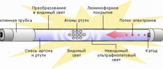
The basic operating principle of electric heating devices is almost the same. To heat, you need to have a heating element - a spiral, which plays the role of an emitter of IR rays, thanks to which forced heating occurs.
Electric kettles have a fairly simple circuit, the main element of which is the heating element. Basically, a flat heating element is used here, which is located at the bottom of the kettle, under a metal lid. The mains voltage enters the spital, which has a certain resistance. The spiral is located inside the heating element. Thermal energy from the spiral is transferred to the heating element, the latter heats the water. The use of a heating element is explained by the fact that it makes the kettle safe; there is no danger of electric shock, since the heating coil element itself does not have direct contact with water, it is not closed to the heating element, so the current is not transmitted to the water. In its simplest form, the electric kettle circuit looks like this:
An electric kettle may have a timer (temporary relay), thermostat, voltage indicator, power switch. More complex circuit diagram:
The thermostat has a standard circuit, unless of course the kettle is expensive. The coil voltage control circuit, in more advanced models, is quite simple - decoupling from a dinistor and a thyristor. The thyristor controls the load, and the dinistor sets the operating mode of the thyristor (essentially controls the thyristor). A dinistor or diode thyristor is essentially a diode that has a certain operating voltage, which is set using a regulator. That is, by controlling the voltage, we can control the temperature. Simply put, the heating element heats the water to the desired temperature - that’s the whole principle of the electric kettle. Nowadays on the market you can find electric kettles with fully automatic control, which will heat the water to a set temperature, then turn off automatically. These include a group of thermos kettles - thermopot. Since the cost of a thermos kettle is quite high, in many cases, independent repair of a thermos is not only justified, but also necessary. The control unit diagram and photo of the printed circuit board with details are shown below:
Kettles with ultrasonic heating are already being tested - a kettle that does not heat up, but heats the water. But the influence of such teapots has not yet been fully studied, so they are very rarely found on sale.
Originally posted 2019-04-07 02:24:32. Republished by Blog Post Promoter
Layout option
All elements can be placed in the housing of an old fluorescent lamp. It already contains everything - the case, the cartridge, the board (which can be reused). Inside, you can arrange all the elements of the power supply and the microcircuit without much difficulty. And on the outside, install an LED that you plan to power from the device. Almost any driver circuits for 220 V LEDs can be used, the main thing is to lower the voltage. This can be easily done with a simple transformer.
It is advisable to use a new circuit board. And it’s better to do without it altogether. The design is very simple, it is permissible to use wall-mounted installation. Be sure to make sure that the voltage at the rectifier output is within acceptable limits, otherwise the microcircuit will burn out. After assembly and connection, measure the current consumption. Please note that if the supply current decreases, the life of the LED element will increase.
Carefully select the driver circuit for powering the LEDs, calculate each design component - service life and reliability depend on this. With the correct selection of drivers, the characteristics of the LEDs will remain as high as possible, and the resource will not suffer. Driver circuits for high-power LEDs differ in that they contain a larger number of elements. PWM modulation is often used, but at home, as they say, “on the knee,” such devices are already difficult to assemble.
Schemes and repair of electric kettles - thermopots
Electric kettles - thermoses, or thermopots, serve regularly for 2 - 3 years, then they usually fail. The main reasons for this are: they stop boiling water, they don’t pour boiling water and because of water leakage. There is a lot of material on the Internet about repairing thermopots, but there are almost no diagrams. The article briefly describes models of thermopots, the diagrams of which are copied from products whose malfunctions the author encountered during repairs. The article provides examples of circuit solutions used in most models of modern thermopots, despite the large number of clones produced by various companies.
In the above diagrams, the designations of most parts correspond to those indicated on the boards. For different models of thermopots, the secondary power supply circuits and control units are very different. All thermopots have a container for boiling water made of stainless steel. Thermal electric heaters, heating elements, usually two of them, are fixed in its lower part for boiling and heating water, in this case they are located in one block, which has three outputs. At the bottom of the container there is a thermal switch for a temperature of 88 - 96 degrees C or a temperature sensor, which gives a signal to turn off the heating element of the boiler when the desired water temperature is reached. On the side wall of the container there are mounted a thermal switch connected in series for a temperature of 102 - 110 degrees C and an FU fuse for 125 degrees C/10A, placed in a silicone tube. They turn off the power supply to the thermopot when the temperature of the boiling container increases due to lack of water or in the event of a short circuit. To supply hot water in thermopots, the same type of 12 V DC electric motors with a centrifugal pump are used.
Most of the thermopot parts are located on two boards. The control board, on which the control buttons and LEDs are located, is located in the upper part of the case. The main board, on which most of the power connectors, control units, relays, sources and secondary voltage stabilizers are located, is located in the lower part of the case under the boiling water container. Both boards are connected to each other by wire harnesses with connectors.
The diagram of the Elenberg TN-6030 thermopot, [1] is shown in Fig. 1. Earlier, in 2014, the author posted it on the go-radio website, so a link to this site is provided. The TN-6030 circuit is quite simple and completely analog. Constantly, a pulsating current flows through the water heating element EK1 and the diode VD9 in only one direction, so the resistance of this heating element is two times less than a similar heating element of the same power in other models, where it is powered by alternating current. When the electric motor is turned on, a constant pulsating current of a different polarity, up to 150 mA, begins to flow through it and the VD10 diode, and alternating current flows through the EK1 heating element. Automatic switching on and off of the heating element for boiling water EK2 is carried out by thermal switch SF1. Forced switching on of the heating element EK2 for up to 2 minutes is carried out by contacts K1.1 of relay K1. To transistors VT1 - VT2 of the control stage of relay K1, a constant voltage of 14 V, stabilized by the chain R3 and VD6, is supplied from the diode bridge VD1 - VD4. A common malfunction of this thermopot model is the burnout of the contacts of the thermal switch SF1, because all the current of the heating element EK2 passes through it. Replacing the thermal switch is not difficult; you just need to unscrew two screws on the flange and rearrange the two power connectors. Detailed videos of this replacement are available on the Internet.
Another malfunction is poor operation of the hot water supply pump. Its reason is an increase in friction on the rotor axis of an electric motor operating at elevated temperatures due to deterioration in the quality of the lubricant. The magnetic clutch of the pump consists of a magnetic disk mounted on the rotor shaft of the electric motor and a pump impeller mounted on the axle shaft in the cover of the pump housing. A magnetic disk is also fixed at the base of the impeller. A sealed gasket is installed between the two magnetic disks. Rice. 2.
The author lubricated the rotor support points at the ends of the electric motor housing with ordinary spindle oil. It helped for a couple of months. It is difficult to get to the front support point, I had to disassemble the pump and pour oil under the magnetic disk, and turn it with my finger, at this moment the electric motor is in a vertical position so that the oil flows into the right place. The remaining oil is poured over the edge. There is no need to remove the disk from the rotor axis; a couple of removals and it will not stay on the rotor axis. It’s easier to immediately replace the engine with the pump.
Water leaks in thermopots rarely occur, usually due to mechanical damage. One day, the cause of water appearing under the kettle turned out to be a barely noticeable crack in the upper part of the plastic case, under the lid, running along the rim of the container for boiling water. Steam penetrated into this crack, which then condensed on the inner surface of the case walls, and the plastic crumbled along the crack. That kettle was beyond repair.
The diagram of the Vitek VT-1188 thermopot is shown in Fig. 3. In this model, a secondary voltage of 12 - 14 V is supplied to the control units from transformer T1, installed at the bottom of the housing under the water tank, and from the rectifier bridge VD1 - VD4. A voltage of 5 V from the ic2 stabilizer is supplied to power the ic1 processor, which controls the entire operation of the thermopot. At the command of optocoupler ic3, processor ic1 should signal the activation of protection, SF1 or FU1, although it is not clear how - a buzzer is not installed in this model. At the bottom of the boiling tank there is an RT temperature sensor installed from two MF58 thermistors connected in parallel with a negative TKS in KD-3 housings. The boiler shutdown temperature is set manually using the sw2 button. Thermopots VT-1188 and VT-1187 do not have a heating element for heating water, which is why turning on and off the heating element for boiling, EK1 occurs more often than in other models. Therefore, in the VT-1188, the relay contacts burn out more often and the heating element burns out. The case of burnout of the relay mounting pin on the board is described in [2]. If all these malfunctions occur, the kettle's display and pump motor work normally, but the water does not boil. If the relay contacts burn and stick, or transistor Q1 breaks down, the boiling mode may not turn off. When repairing these breakdowns, faulty parts are replaced.
Photo of the main board VT-1188. Rice. 4.
The VT-1191 thermopot diagram is shown in Fig. 5. The secondary voltage source for the control units is pulsed, made on the VIPer 12A microcircuit using a transformerless circuit. The constant voltage of 18 V at its output is filtered by capacitors EL3, C3 and inductor L2, then reduced by the zener diode ZD2 to 12 V. The control circuit operates on the ic1 processor, there are no markings on its body, there is only a label indicating the model of the thermopot. A voltage of 5 V is supplied to ic1 from the stabilizer on transistor Q4 and zener diode ZD3. The VT-1191 thermopot has two heating elements: EK1 for boiling and EK2 for heating water. Contacts K1,1 of relay K1 alternately connect the terminals of one of them to the network, depending on the voltage at pin No. 5 of ic1, which is supplied to the base of transistor Q1 through connector CN1, LED HL2 and R7. A small base current of transistor Q2 flows through thermal switch SF2, so SF2 is connected to the board and pin No. 4 of ic1 with a low-current connector. The electric motor is turned on by transistor Q3 when “+” appears at pin No. 3 of ic1. The malfunction of the thermopot was manifested in the fact that it did not boil or pour water, only the green HL3 indicator was on. The cause of the breakdown was the failure of the ic1 processor.
Fig.6 Photo of the main board VT-1191, fixed in the thermopot housing.
A lot of advice on repairing thermopots has already been given, but I’ll add two more:
1) Take photographs of the entire process of disassembling and repairing the kettle. This will then facilitate its subsequent assembly and especially the installation of power connectors. (Fig. 6).
2) If the housings of low-current connectors installed on boards wobble even slightly in their places, these housings must be glued to the board and the contacts must be soldered. Failure of connector contacts after repair and assembly of the thermopot can lead to new malfunctions.
Author: Panshin Andrey. Moscow.
Bibliography
- https://go-radio.ru/remont-termopot.html
- “Repair of electric kettle relay Vitek VT-1188”
- Radio magazine 2016-8-35.
Tags:
- Repair