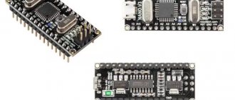
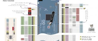
This review identifies 10 common applications for controlling Arduino from a computer or phone that are easy to learn and use. Arduino is a platform designed in view of modern programming technologies. Board with USB connectors for power supply. When connected to a PC, it charges. The internal system has a button to format the data.
Main components:
- Bradboard – connects the platform to the device.
- The LED is an indicator that signals control.
- Resistor - controls the flow of electrical current within the platform.
- Photoresistor - reacts to the type of lighting.
- Transistor – amplifies electrical signals and is used in complex circuits.
This was an internal description. Next we move on to a review of the application itself. Google has created a new application programming interface called Arduino. Designed to connect an Android device to USB. Opens up great opportunities for creating projects and simplifies programming and control from the mobile phone screen. Helps manage data synchronization.
Overview of Arduino features:
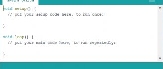
- creating sketches;
- editing, compiling and loading them on the board;
- programming and code development.
The work is done from a smartphone from any part of the globe. This review will describe programs developed for remote use of Arduino, namely Bluetooth and Wi-fi controllers. They are easy to use and allow you to work from any gadget. The Arduino project consists of 3 stages:
- writing code;
- prototyping;
- firmware.
To program these functions, you need to write code that can be deleted as needed and flash the development environment. This is a multi-step process. Several programs participate in it.
Arduino Bluetooth Controller
This program works in 3 main positions:
Controller. The application is displayed in the form of a play identifier and is controlled by switch buttons. It operates with one key, the main function of which is remote control.
Dimmer. From a distance, adjusts brightness and speed settings.
Terminal. Implementation of sending directive for decryption.
Installing the Arduino Bluetooth Controller app connects multiple devices over the air. Messages are transmitted to sensors, controllers and back. By controlling a smartphone using Bluetooth modules, it is also possible to organize a wireless connection for an entire project. Programming of this type is accessible to everyone and does not require much effort.
ArduinoDroid - Arduino IDE
Used by programmers as a means of editing codes and creating programs. Feature - the written sketch is converted into CC+, compiled and loaded into Arduino. Great for those new to the field. The application can be used free of charge and in the public domain.
The first step in use will be to upload the sketch to the microcontroller. Next, by clicking the “Download” button, you must wait for the download to complete. A flashing LED means everything was done correctly. Everything is ready to write and use firmware.
ArduinoDroid is easy to use software. Edits, compiles and uploads codes to the board from a mobile device or tablet. It is also recommended to edit the cipher or upload a ready-made one if the program is banned..
Instead of an introduction
I would like to say right away that in this article I will not delve very deeply into the intricacies of programming; it is assumed that the reader has at least the minimum basics.
I’ll tell you in general how the resources were used and interesting points. The prerequisites for creating this method arose during the creation of my electric car: Click here! I will say right away that this was created more out of sporting interest than for serious practical work, but nevertheless it works and can be useful to someone.
RemoteXY: Arduino Control
This Arduino control program allows you to create a personal panel. Remote control occurs via:
- Internet;
- Wi-Fi;
- IR port;
- Bluetooth.
On the page https://remotexy.com you can find and download many interesting instructions. For example, how to create original keys and switches. The functionality is adapted for beginners and will not create problems in use.
Controlling Arduino from a computer, namely RemoteXY, is possible via the cloud. This makes it superior to similar Russian Arduino software.
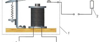
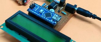
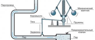
Schematic diagram
Let's connect the Ethernet shield to the Arduino motherboard. And the electromagnetic relay is already connected to the expansion board. We use 5 volt power and ground. And to control the relay, we’ll take digital pin 7.
Schematic diagram of connecting Ethernet shield and relay
Blynk app
A sort of idea developer with an open door to launch on the Arduino platform. The main requirement for use is the presence of the Internet: Wi-Fi or mobile traffic. Only in this case will Blynk be ready for execution. You can start using it a few minutes after completing the settings. The program supports the AO of the user's choice.
The main functions of the Blynk application are to manage devices by removing and adding HTTP protocols, as well as GET and POST requests. Parameter values can be updated and retrieved. Requests are updated in the application itself.
Variability is an important point of the program. Having a connection with running platforms, you can connect to the server in any convenient way. This instinctive portal is easy to use on a project. The library is constantly updated for all Arduino Blynk applications.
Customers who want to turn on the coffee machine from their smartphone will be interested in this application. This is perhaps the only service with such capabilities. And despite the fact that it is practically unlimited, Openhab is difficult. Compared to other services, it has fast startup speed.
Bluino Loader – Arduino IDE
Software for compiling code into a file and uploading it to the Arduino platform via smartphone and USB OTG. Bulky buttons and tangled wires make projects much more difficult. For simplified remote administration control, a Bluino Loader IDE graphical ID is provided. Develops projects available to the trigger. Connects to the World Wide Web using: Wi-Fi, Ethernet or via an ESP8266 drive. When the necessary procedures are completed and work starts, the application will give a signal.
Setting up the software to create projects will take no more than 5 minutes. The software is configured according to the user's choice. Simple and convenient software. To check, upload the sketch to the microcontroller and make sure that everything works as it should. A flashing diode will signal that the actions performed are correct. Next we proceed to the firmware.
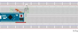
Programming nRF24L01 for Arduino
Using these modules with Arduino is very easy thanks to the available ready-made library created by maniacbug on GitHub. Click on the link to download the library as a zip directory and add it to the Arduino IDE using Sketch → Include Library → Add .ZIP library. After adding the library, we can start programming for the project. We have to write two programs, one for the transmitting part and the other for the receiving part. However, as I said earlier, each module can act as both a transmitter and a receiver. Both programs are given at the end of the page , in the transmitter code the receiver code will be commented out, and in the receiver program the transmitter code will be commented out. You can use it if you want the module to work in both modes in your project. The operation of the program is described below.
As with all programs, we start by including the header files . Since nRF uses the SPI protocol, we have included the SPI header file as well as the library we just downloaded. The servo library is used to control the servo motor.
#include #include "RF24.h" #include
Next comes an important line in which we indicate the CE and CS pins . In our circuit diagram, CE is connected to pin 7 and CS is connected to pin 8.
RF24 myRadio (7, 8);
All variables that are associated with the RF library must be declared as a compound structure. In this program, the msg variable is used to send and receive data from the RF module.
struct package { int msg; }; typedef struct package Package; Package data;
Each RF module has a unique address, using which you can send data to the corresponding device. Since we only have one pair here, we set the address to zero on both the transmitter and receiver , but if you have multiple modules, you can set the ID to any unique six-digit string.
byte addresses[][6] = {"0"};
Then, inside the void setup() function, we initialize the RF module and configure it to operate in the 115 band , which is noise-free, and also configure the module to operate in low-power mode with a minimum speed of 250 kbps.
void setup() { Serial.begin(9600); myRadio.begin(); myRadio.setChannel(115); // range 115 above WiFi signals myRadio.setPALevel(RF24_PA_MIN); // minimum output power myRadio.setDataRate( RF24_250KBPS ) ; // minimum speed myservo.attach(6); Serial.print("Setup Initialized"); delay(500); }
The void WriteData() function writes the data passed to it. As stated earlier nRF has 6 different channels in which we can write and read data, here we have used 0xF0F0F0F066 as the address to write data. In the receiving part, we have to use the same address in the ReadData() function to receive the data.
void WriteData() { myRadio.stopListening(); // Stop receiving and start transmitting myRadio.openWritingPipe(0xF0F0F0F066); // Send data to this 40-bit address myRadio.write(&data, sizeof(data)); delay(300); }
The void WriteData() function reads data and puts it into a variable. Again from the 6 different channels through which we can read and write data, here we have used 0xF0F0F0F066 as the address to read the data. This means that the transmitter of another module wrote something to this address, and therefore we are reading this something from the same address.
void ReadData() { myRadio.openReadingPipe(1, 0xF0F0F0F0AA); // Which channel to read from, 40-bit address myRadio.startListening(); // Stop transmitting and start receiving if ( myRadio.available()) { while (myRadio.available()) { myRadio.read( &data, sizeof(data) ); } Serial.println(data.text); } }
Apart from these lines, the program uses other lines to read the position of the potentiometer and convert this reading into a value ranging from 0 to 180 using the map function and send it to the receiving module where we control the servo accordingly.
Arduino Bluetooth Control
The abbreviated name is ABC. Manages and monitors core API capabilities. Used in contact monitoring via Bluetooth. Works offline. Introduction to work is carried out strictly from Arduino.
Tools used in the process:
- Metrics – reports metrics about failures and changes. Those, in turn, come to the phone in the form of a message about stopping work. This is a kind of function where by shaking the gadget you can send data.
- Directional keys – used to send information.
- Terminal – varies information with time indicators according to purpose.
- Accelerometer – gesture control. The smartphone turns into a mechanism for regulating the car.
- Voice – creates speech commands. Voice communication with the robot is available.
- Buttons – 6 of them function in a horizontal position. Used to deliver information to Arduino.
Managing projects remotely and remotely has become a frequent necessity. ABC is 100% suitable for these purposes. UART (Serial) is intended for wireless connection between Arduino and PC. This connection does not require libraries or circuits.
Code
Transmitting part code
/* Sends potentiometer position via NRF24L01 using Arduino * * Pin connections * CE - 7 MISO - 12 MOSI - 11 SCK - 13 CS - 8 POT - A7 */ #include #include "RF24.h" RF24 myRadio (7, 8 ); struct package { int msg = 0; }; byte addresses[][6] = {"0"}; typedef struct package Package; Package data; void setup() { Serial.begin(9600); myRadio.begin(); myRadio.setChannel(115); // Band 115 is above WIFI myRadio.setPALevel(RF24_PA_MIN); // minimum output power myRadio.setDataRate(RF24_250KBPS); // Minimum speed delay(500); Serial.print("Setup Initialized"); } void loop() { int Read_ADC = analogRead(A7); char servo_value = map(Read_ADC, 0, 1024, 0.180); if (servo_value>1) data.msg = servo_value; WriteData(); delay(50); // ReadData(); //delay(200); } void WriteData() { myRadio.stopListening(); // Stop receiving and start transmitting myRadio.openWritingPipe( 0xF0F0F0F0AA); // Send data to this 40-bit address myRadio.write(&data, sizeof(data)); Serial.print("\nSent:"); Serial.println(data.msg); delay(300); } void ReadData() { myRadio.openReadingPipe(1, 0xF0F0F0F066); // Which channel to read, 40-bit address myRadio.startListening(); // Stop transmitting and start receiving if (myRadio.available()) { while (myRadio.available()) { myRadio.read(&data, sizeof(data)); } Serial.print("\nReceived:"); Serial.println(data.msg); } }
Receiving part code
/* CE - 7 MISO - 12 MOSI - 11 SCK - 13 CS - 8 POT - A7 Recently tested with Nano */ #include #include "RF24.h" #include Servo myservo; RF24 myRadio (7, 8); struct package { int msg; }; typedef struct package Package; Package data; byte addresses[][6] = {"0"}; void setup() { Serial.begin(9600); myRadio.begin(); myRadio.setChannel(115); // Band 115 is above WIFI myRadio.setPALevel(RF24_PA_MIN); // minimum output power myRadio.setDataRate(RF24_250KBPS); // Minimum speed myservo.attach(6); Serial.print("Setup Initialized"); delay(500); } int Servo_value; int Pev_servo_value; void loop() { ReadData(); delay(50); Pev_servo_value = Servo_value; Servo_value = data.msg; while (Pev_servo_value< Servo_value) { myservo.write(Pev_servo_value); Pev_servo_value++; delay(2); } while (Pev_servo_value> Servo_value) { myservo.write(Pev_servo_value); Pev_servo_value—; delay(2); } //data.msg = “nothing to send”; //WriteData(); // delay(50); } void ReadData() { myRadio.openReadingPipe(1, 0xF0F0F0F0AA); // Which channel to read, 40-bit address myRadio.startListening(); // Stop transmitting and start receiving if ( myRadio.available()) { while (myRadio.available()) { myRadio.read(&data, sizeof(data)); } Serial.print("\nReceived:"); Serial.println(data.msg); } } void WriteData() { myRadio.stopListening(); //Stop receiving and start transmitting myRadio.openWritingPipe(0xF0F0F0F066);//Send data to this 40-bit address myRadio.write(&data, sizeof(data)); Serial.print("\nSent:"); Serial.println(data.msg); delay(300); }
BT Voice Control for Arduino
The main purpose of this software is to transmit ultrasonic signals through transducers. They are connected to the Arduino android platform thanks to the Bluetooth port. The main module in operation is HC-05. It conveys the spacing between objects. The data is displayed on the smartphone and on the Hub disk of the portal through this application.
BT Voice Control is Arduino voice control. It has the command recognition function: forward, back, left, right. Sensitive sensors forward the distance to the Arduino object. Then, using the Bluetooth module, the HC-05 sends it to the application. The program will save time spent typing commands manually.
Virtuino
An Android program designed to monitor the sensor. Controls electrical devices via Bluetooth, Wi-Fi or the Internet.
With the help of Virtuino you can create:
LEDs;
buttons;
switches;
task displays;
tools;
regulators.
The application is able to combine several projects into one. Controls excellent platforms simultaneously via Bluetooth and Wi-fi. Free to use. Belongs to the System Maintenance subcategory. It is possible to design interior design with different visualizations.
These include:
- LEDs;
- switches;
- diagrams;
- counters;
- analog devices.
You can learn Virtuino using tutorials and video lessons with library support. For now the application works in English mode.
What is the entire system based on and how is it implemented in hardware?
The workflow is as follows: we read the file containing the data from the server using a program running on a PC/laptop. This program sends data to the controller via USB. The controller receives data and performs actions on it. The scheme with a server is attractive because you can manage the scheme without an application, simply by accessing the site from any smartphone/tablet/PC/laptop anywhere in the world where there is access to the Internet.
PS. The server part is described below.
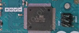
In this article I will control the Arduino MEGA 2560 (Chinese equivalent), but behind the scenes the circuit worked smoothly with the PIC16F877A, the only thing I had to use was a USB-TTL adapter:
Of course, the program for PIC is somewhat different from the program for Arduino, due to different types of MK, but the principle is the same:
We receive data via the COM port, compare it with the internal command table and perform the appropriate action.
The scheme initially seemed very simple to me, but there was one BUT - there was no program that would read a file on the Internet and send the data to the COM port. Accordingly, such a program had to be written. The program was written in VB6. To read a file from the server, the VB6 component is used: Microsoft Internet Transfer Control 6.0. It simply reads a text file on the server into a string variable. Once read, this string is sent to the COM port using the VB6: Microsoft Comm Control 6.0 component. The entire process of reading a file and sending a string is read in a loop using a timer. The timer interval can be changed in the program config, or directly during operation. In addition, you can select the port operating mode, its number, Internet connection operating mode and a link to the file to be read.
I would like to make a note that with large file sizes and small intervals the program freezes, but continues to work. The buffer size of my program is 512 bytes. Considering that my MK has a smaller buffer, this is enough.
Important point. The program in MK does not know how to parse data, it can only read which character was transmitted to the input via the serial port. Without errors, I was able to accept the Latin alphabet (26 characters AZ and 10 numbers 0-9). A total of 36 commands, if the algorithm is modified and data parsing is introduced into the MK, then any data can be transferred. There is also the possibility of “doping” the software for two-way data exchange.
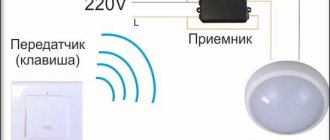
Bluetooth Controller 8 Lamp
The Arduino platform was created in 2003. It achieved universal attention thanks to its low price, as well as a multi-million dollar community aimed at in-depth study of programming. Microprocessors and microcontrollers come with boards. Arduino is considered the most popular. Italian models have many functions to expand and explore built-in Pro systems.
Bluetooth Controller 8 Lamp is designed to regulate the functions of Arduino with an 8-channel controller. Works using Bluetooth modules HC-05, HC-06 and HC-07. 8 button interface corresponds to each light bulb.
The method is active only within visibility. Compared to other wireless methods, this is the cheapest. Board components cost less than $1. Even used options are suitable for the job. Static devices, using an infrared controller in ceiling LED strips, easily solve problems that arise during the process.