When a charge is imparted to a conductor, a potential φ appears on its surface, but if the same charge is imparted to another conductor, the potential will be different. This depends on the geometric parameters of the conductor. But in any case, the potential φ is proportional to the charge q
.
The SI unit of capacitance is the farad. 1 F = 1 C/1 V.
If the potential of the sphere surface
| (5.4.3) |
| (5.4.4) |
More often in practice, smaller units of capacitance are used: 1 nF (nanofarad) = 10 –9 F and 1 pkF (picofarad) = 10 –12 F.
There is a need for devices that accumulate charge, and isolated conductors have low capacity. It was experimentally discovered that the electrical capacity of a conductor increases if another conductor is brought close to it - due to the phenomenon of electrostatic induction
.
Capacitor
- these are two conductors, called
plates
, located close to each other
.
The design is such that the external bodies surrounding the capacitor do not affect its electrical capacity. This will be done if the electrostatic field is concentrated inside the capacitor, between the plates.
Capacitors are flat, cylindrical and spherical.
Since the electrostatic field is inside the capacitor, the electric displacement lines start on the positive plate, end on the negative plate, and do not disappear anywhere. Consequently, the charges on the plates are opposite in sign, but identical in magnitude.
The capacitance of a capacitor is equal to the ratio of the charge to the potential difference between the plates of the capacitor:
| (5.4.5) |
In addition to the capacitance, each capacitor is characterized by U
slave (or
U
pr
.
) - the maximum permissible voltage, above which a breakdown occurs between the plates of the capacitor.
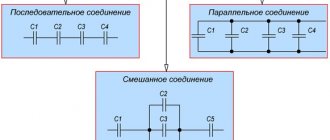
Capacitive batteries
– combinations of parallel and series connections of capacitors.
1) Parallel connection of capacitors (Fig. 5.9):
In this case, the common voltage is U
:
Compare with parallel connection of resistances R
:
Thus, when connecting capacitors in parallel, the total capacitance
The total capacity is greater than the largest capacity included in the battery.
2) Series connection of capacitors (Fig. 5.10):
The common charge is q.
Or
, from here
Compare with serial connection R
:
Thus, when capacitors are connected in series, the total capacitance is less than the smallest capacitance included in the battery:
Calculation of the capacitances of various capacitors
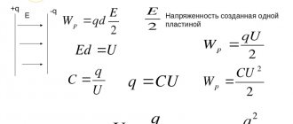
Field strength inside the capacitor (Fig. 5.11):
Voltage between plates:
where is the distance between the plates.
Since the charge is
| . | (5.4.7) |
As can be seen from the formula, the dielectric constant of a substance greatly affects the capacitance of the capacitor. This can also be seen experimentally: we charge the electroscope, bring a metal plate to it - we get a capacitor (due to electrostatic induction, the potential has increased). If you add a dielectric with ε greater than that of air between the plates, then the capacitance of the capacitor will increase.
From (5.4.6) we can obtain the units of measurement ε 0:
.
The potential difference between the plates of a cylindrical capacitor shown in Figure 5.12 can be calculated using the formula:
How to calculate the capacity of the quenching capacitor of a simple power supply
A power supply with a quenching capacitor is the simplest option for powering some low-power device.
For all its simplicity, it also has two disadvantages: 1. It is galvanically connected to the network! Therefore, such power supplies are used where there is no possibility of touching the contacts. 2. Such a power supply does not have a very large output current. As the output current increases, it is necessary to increase the capacity of the quenching capacitor and its dimensions become significant.
Attention, be very careful not to touch the contacts of this power supply when it is turned on.
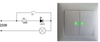
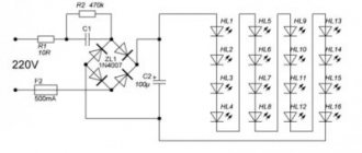
The simplest diagram of this power supply looks like this:
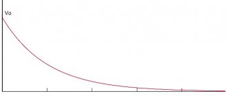
As you can see from the diagram, there is a capacitor in series with the network. It is then the ballast, on which part of the voltage is extinguished. The capacitor does not pass direct current, but since the network is alternating and the capacitor is eventually constantly recharged, it turns out that in this case there is current at the output. Moreover, the current strength directly depends on the capacitance of the capacitor.
That’s why, in order to calculate the capacitance of the capacitor, it is necessary to know at least the output current of our future power supply, and we must also take into account the consumption of the stabilizer, usually several mA.
So. There are two formulas, complex and simple. Complex – suitable for calculations at an arbitrary output voltage. Simple - suitable in situations where the output voltage is no more than 10% of the input. I – output current of our power supply unit Uin – network voltage, for example 220 Volts Uout – voltage at the output of the power supply unit (or to the stabilizer if there is one), for example 12 Volts. C is the actual required capacity.
For example, I want to make a power supply with an output current of up to 150mA. An example of the circuit is given above, the application option is a radio remote control with a 5 Volt power supply + a 12 Volt relay. We substitute our 0.15 Amperes and get a capacity of 2.18 μF, you can take the nearest standard value - 2.2 μF, or "according to the imported" – 225.
Everything seems to be fine, the circuit is simple, but there are several disadvantages that need to be eliminated: 1. An inrush of current when turned on can burn out the diode bridge. 2. If the capacitor fails, there may be a short circuit 3. If you leave it as is, then it is quite possible to get a discharge from the input capacitor, since voltage may be present on it for a long time even after disconnecting the power supply from the network. 4. When the load is removed, the voltage on the capacitor before the stabilizer will rise to a fairly large value.
Solutions: 1. Resistor R1 in series with the capacitor 2. 0.5 Ampere fuse. 3. Resistor R2 is parallel to the capacitor. 4. 12 Volt suppressor in parallel with the capacitor after the diode bridge. I do not recommend using zener diodes here; suppressors are designed for greater power dissipation and the circuit will work more reliably.
In the diagram, I highlighted the new components in red, and a small addition in the form of an LED in blue.
But quenching capacitors are often used in cheap LED lamps. This is bad, since such lamps are less reliable and often have high light pulsations. Below is a simplified version of the diagram of such a lamp.
Let's try to calculate the capacitance for such an application, but since the output voltage will clearly be more than 1/10 of the input, we will apply the first formula. I set the output voltage to 48 Volts, 16 LEDs of 3 Volts each. Of course, this is all conditional, but close to reality. Current – 20mA, the typical maximum current for most indicator LEDs.
It turned out that a capacitor with a capacity of 0.298 µF is needed. The closest common value is 0.27 or 0.33 µF. The first one is much less common, and the second one will already produce an excess current, so you can make a capacitor from two parallel ones, for example, 0.15 μF each. When connected in parallel, the capacity is folded.
We've sorted out the capacitance, there are still a couple of points left: 1. Capacitor voltage 2. Capacitor type.
With voltage, everything is simple, you can use a 400 Volt capacitor, but 630 is more reliable, although they are larger.
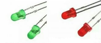
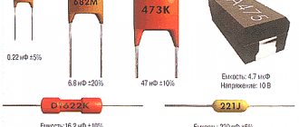
The type is a little more complicated. For this application, it is better to use capacitors that were originally intended for such use, for example K73-17, CL21, X2 Capacitor CL21 is shown in the photo
And this is a more reliable option, don’t look at the fact that it says 280 Volts, it has an alternating effective voltage value and will work more reliably than K73-17 or CL21.
Such capacitors may look like this
But now you can once again carefully look at what is needed in order to assemble such a "simple" power supply and decide whether it is needed. In some situations, yes, it will help, but it has a bunch of disadvantages, so in my opinion it is better to use just a small switching power supply, which already has a stabilized output voltage, galvanic isolation and a higher output current. As an example of such power supplies, I can provide a link to a detailed review of four options, with tests, diagrams and inspections.
But you can do even better. Now monolithic power supplies have become widespread. Essentially a cube containing a miniature power supply. For example, HLK-PM01 manufactured by Hi-link, costing about two dollars apiece.
Or their Chinese counterpart TSP-05 produced by Tenstar robot. They are a little cheaper at $1.93 each. Practice has shown that their quality is comparable.
As I wrote above, they are a modular pulse power supply. PSU in a plastic case filled with epoxy resin. They are available in different voltages and are able to maintain it at a fairly stable level.
A closer look at the insides, the photo shows a version from Hi-link
That seems to be all. I hope that the article was useful, and I will try to find interesting topics in the future. We are also interested in suggestions about what we would like to see in the Beginners section.
A simple LED power supply circuit with a capacitor
Let's look at a device without a transformer power supply for LEDs using the example of a factory LED lamp driver.
- R1 – 1W resistor, which reduces the significance of voltage drops in the network;
- R2,C2 – the condenser serves as a current limiter, and the resistor is for discharging it after disconnecting from the network;
- C3 – smoothing condenser, to reduce light pulsation;
- R3 - serves to limit voltage drops after conversion, but it is more advisable to install a zener diode instead.
What capacitor can be used for ballast?
Ceramic elements designed for 400-500V are used as quenching capacitors for LEDs. The use of electrolytic (polar) capacitors is prohibited.
Precautionary measures
Transformerless circuits do not have galvanic isolation. The current strength of the circuit when additional resistance appears, for example, touching a bare contact in the circuit with your hand, can increase significantly, causing electrical injury.
Please rate the article. We tried our best:)
Did you like the article? Tell us about her! You will help us a lot :)
Driver for LED lamp 10w version 2 with ballast capacitor and protection
Let's start by analyzing the classic circuit with a ballast capacitor. Ballast capacitor C1, being a current source, having received voltage from fuse F1 and limiting resistor R1, designed to protect the ballast from an inrush current when first turned on, limits the current in turn, and the direct current source rectified by the diode bridge D1 is sent to the LED chain led1-led12. The advantages of this scheme are simplicity, availability of parts, and are not afraid of short-circuit at the output. But there are significant drawbacks: 1. The presence of ripples of 100 Hz at the output of the filter capacitor, which, however, can be removed by increasing the capacitance of the filter capacitor C2 to 500 μF, since after the diode bridge the voltage amplitude reaches up to 310 volts, the filter capacitor must withstand this voltage, and we select it plus some reserve, out of harm’s way, let it be 400 volts, but now imagine what its dimensions will be.
The principle of operation of circuits using a ballast capacitor
In this circuit, the condenser is a current filter. Voltage is supplied to the load only until the condenser is fully charged, the time of which depends on its capacity. In this case, no heat generation occurs, which removes restrictions on load power.
To understand how this circuit works and the principle of selecting a ballast element for an LED, let me remind you that voltage is the speed of electrons moving along the conductor, and current is the electron density.
For a diode, it is absolutely indifferent at what speed electrons will “fly” through it. The calculation of the conductor is based on the current limitation in the circuit. We can apply at least ten kilovolts, but if the current is several microamps, the number of electrons passing through the light-emitting crystal will be enough to excite only a tiny part of the light emitter and we will not see the glow.
At the same time, at a voltage of several volts and a current of tens of amperes, the electron flux density will significantly exceed the throughput of the diode matrix, converting the excess into thermal energy, and our LED element will simply evaporate in a cloud of smoke.
What is the difficulty?
The problem of connecting an LED to a 220 volt network is caused by its technical characteristics. To glow, an LED lamp passes current in one direction.
A voltage of 220 V with a frequency of 50 Hz is supplied from the network; the diode can only operate at half-waves. This means that it flashes at the same frequency as the current from the network. When passing in the opposite direction, the voltage has the opposite polarity, which does not allow light to glow and contributes to the destruction of the crystals.
Important! Connecting an LED to a 220-volt power supply requires connecting a device that will supply as much current as the lamp requires to glow.
The principle of operation of circuits using a ballast capacitor
In this circuit, the condenser is a current filter. Voltage is supplied to the load only until the condenser is fully charged, the time of which depends on its capacity. In this case, no heat generation occurs, which removes restrictions on load power.
To understand how this circuit works and the principle of selecting a ballast element for an LED, let me remind you that voltage is the speed of electrons moving along the conductor, and current is the electron density.
For a diode, it is absolutely indifferent at what speed electrons will “fly” through it. The calculation of the conductor is based on the current limitation in the circuit. We can apply at least ten kilovolts, but if the current is several microamps, the number of electrons passing through the light-emitting crystal will be enough to excite only a tiny part of the light emitter and we will not see the glow.
At the same time, at a voltage of several volts and a current of tens of amperes, the electron flux density will significantly exceed the throughput of the diode matrix, converting the excess into thermal energy, and our LED element will simply evaporate in a cloud of smoke.
Connection diagrams
There are 3 options to reduce voltage:
The first method is the simplest. The quenching resistor (resistance) must be connected to a 220 V network in series with the diode, taking into account the amplitude voltage value of 310 V (220 V * 1.41). To protect against the negative effects of reverse voltage, an additional diode (voltage from 400 V) should be connected back-to-back. This allows the volts to be turned to resistance.
The same principle is used if you need to connect several LED lamps back-to-back. Each of them burns in a separate section of the sinusoid frequency, protecting each other.
Both circuits have an important drawback - the release of high power across the resistance. It turns into heat. Additionally, a powerful resistor must be connected to ensure optimal performance.
If there are several lamps and they consume a lot of current, as the power increases in proportion to the square of the current, connecting a resistor is not advisable from the point of view of energy costs. In such situations, it is replaced with a non-polar capacitor with a power of 400 V or more. The main advantage is the absence of power dissipation, the disadvantage is storage of the residual charge after disconnection. It can be eliminated by attaching an additional discharge resistance.
To connect multiple LED bulbs, a series connection via a capacitor is used. It is important that all light sources are the same. The storage capacity must be determined depending on the number of diodes.
Parallel connection of LEDs to a 220 V network is not allowed.
Capacitors for LED light bulbs
Why did I order these capacitors?
The answer is banal. To “collectively farm” LED lighting. Where else can they be used? I'll tell you how to calculate the ballast capacity for an LED light bulb. Control review. For those who are not afraid to use such drivers, let's go. For those who do not respect such schemes, there is no need to enter. First, as usual, let's see what was in the package
Well, now let's get down to business. We take a standard Chinese light bulb. Here is its diagram (slightly improved).
Added R4, it will be instead of a fuse, and will also soften the starting current. The current through the LEDs determines the rating of capacitance C1. Depending on what current we want to pass through the LEDs, we calculate its capacity using formula (1).
For calculations, we need to know the voltage drop across the LEDs. It's easy to calculate. The LED behaves in the circuit like a zener diode with a stabilization voltage of about 3V (there are exceptions, but very rare). When LEDs are connected in series, the voltage drop across them is equal to the number of LEDs multiplied by 3V (if there are 5 LEDs, then 15V, if 10 - 30V, etc.). Let's say we want to make a light bulb with ten 5730smd LEDs. According to the passport data, the maximum current is 150mA. I am not a supporter of violence. Therefore, we calculate the light bulb at 100mA. There will be a power reserve. And the supply, as they say, is not enough for the pocket. Using formula (1) we get: C=3.18*100/(220-30)=1.67 μF. The industry does not produce such a capacity, not even the Chinese one. We take the nearest convenient one (we have 1.5 μF) and recalculate the current using formula (2). (220-30)*1.5/3.18=90mA. 90mA*30V=2.7W. This is the rated power of the light bulb. It's simple. In life, of course, it will be different, but not much. It all depends on the actual voltage in the network, the exact capacity of the ballast, the actual voltage drop across the LEDs, etc. By the way, using formula (2) you can calculate the power of light bulbs already purchased. The voltage drop across R2 and R4 can be neglected; it is insignificant. You can connect quite a lot of LEDs in series, but the total voltage drop should not exceed half the mains voltage (110V). If this voltage is exceeded, the light bulb reacts painfully to all changes in the network voltage. The more it exceeds, the more painfully it reacts (this is friendly advice). And yet, let’s check how accurate the capacity ratings are. First 2.2 µF.
Now 1uF.
The errors are small, no more than 2%. You can safely take it. Let's move on to practical application. If anyone is interested, look where I applied it. This was already in one of the previous reviews, so I hid it under a spoiler.
Excerpt from panel review
In one of my reviews I connected panels to a driver on a Conder. This is the light bulb made from an energy-saving lamp. Let me remind you that the module consists of five parallels. Each parallel contains 18 2835smd LEDs. Voltage drop 51V.
Let's calculate the current from formula (2): We get current =(220-51)*2.2/3.18=117mA. 51V*117mA=6W LED power (66.7mW for each LED - 33% of the nominal) - the calculated power of the lamp. We assemble and turn on. WORKS!
But such light bulbs cannot be used without protective glass or a plastic diffuser. All LEDs are under phase and cannot be touched in operating mode. Now let's see what the instruments show. Where would I be without them?
The device showed 5.95W. Of course, such a light bulb can only be used in a barn. And people have sheds and garages. And something needs to be screwed in there too (the village version, I’ll explain why). In the summer I often go to the village. But in the countryside, the voltage does not rise above 200V; sometimes it can be lower. Now let’s calculate the power of our light bulb at 180V in the network. Using the same formula, we first find the current that flows through the LEDs. Only instead of 220V in the formula we will put 180V. Total 110mA*51V=5.6W. As you can see, the power has hardly changed. But incandescent light bulbs smoke at this voltage. Option with garage. In the garage, on the contrary, I don’t have time to change light bulbs - at least 240V. Let's calculate the current and power at 260V, all using the same formula. We have: 145mA*51V=7.4W (41% of maximum power). Burnout is too far away. Conclusion: it will light at 180V and will not burn out at 260V. Now I’ll try to evaluate the quality characteristics of the light. Tried to light the wall
It shines very brightly, with a warm, pleasant light, brighter than a 60W incandescent lamp (picture below). You can compare brightness and color tone. Everything was filmed under the same conditions, at the same distance from the wall.
I also measured the power of the incandescent lamp for the purity of the experiment, with the same device under the same conditions. Incandescent lamp – 56.5 W. LED lamp – 5.95W. I inserted both light bulbs one by one into a table lamp with a reflector. You saw him.
Now a clipping from my last review. True, I added dimensions.
Excerpt from the review About 1W LED Bulbs High power diodes
Using these LEDs I decided to remake the lamp.
The light bulbs have already deteriorated, and the new ones are of low quality.
I decided to connect the lamp via condensers; I don’t need a lot of power, and I’ll save the electronic driver for something more worthwhile. And here is the diagram.
I connect all the diodes in series.
I also made the board for the driver from what I had (quickly). There was even a pin for fastening. I did not remove the throttle. I left it for weight, otherwise the lamp will fall.
I did it according to all electrical safety rules. Not a single energized element comes out. The board is secured with printed conductors inside. Let's calculate the power of the resulting light bulb. First, using formula (2), we find the current through the LEDs with a ballast capacity of 3.2 μF. (220-18)*3.2/3.18=203.2mA. 203.2mA*18V=3.66W – calculated power (at a network voltage of 220V). We look at the device
The device shows 3.78W. But the socket is 232V, not 220V. The error is minimal. And, as usual, let's see how it shines.
This is a 40W light bulb. Naturally, all light bulbs are in equal conditions (shutter speed on the handbrake, the distance to the wall is the same). This is my LED light. The photo exposure meter tells you that the light is brighter than forty. And finally, the third device where they (conders) can be used. I have been using a homemade charger for many years.
Additional Information
Now let's try to summarize. I will try to highlight all the pros and cons of such schemes. -During operation, you categorically cannot touch the circuit elements, they are under phase. -It is impossible to achieve high currents of LEDs, since this requires large capacitors. - Large pulsations of the light flux with a frequency of 100 Hz require large filter capacities at the output. +The circuit is very simple and does not require any special skills in manufacturing. + Does not require special material costs during production. Most parts can be found in any shed or garage (old TVs, etc.). +Indispensable as an initial LED experience, as the first step in mastering LED lighting. I wrote my vision, my attitude to such schemes. It may differ from yours. But I expressed it. And as always, it’s up to you to draw the conclusion. That's all. I will not return to a detailed analysis of such schemes. Worn them out from top to bottom. And at the end for those who keep track of the tracks.
Additional Information
That's all! Good luck everyone.
mysku.ru
Ripple
Ripple is observed in LEDs equipped with a low-quality driver. Most often, the capacity of the built-in capacitor is not enough for normal operation.
How to reduce pulsation
To reduce ripple, it is theoretically possible to power the diode from a powerful storage capacitor (capacitance from 100 μF). But it is expensive and relatively large in size. When replacing it with a resistor, the level of illumination and efficiency decrease simultaneously with pulsation. Plus – extending the life of the LED.
Calculation of the capacitance of the smoothing capacitor
The charge storage device for smoothing out pulsations is most often electrolytic, with a large capacity.
Attention! To connect it correctly to the rectifier, it is important to observe the polarity. If there is no rectifier, you need to connect the working zero to the lamp, the 220 V phase to the storage device. The grounding wire is also connected to the lamp.
To calculate the capacity, the formula is used: C=4.45*I/U-UD, where:
- I – current passing through the diode (in milliamps);
- UD – voltage reduction in the LED lamp.
U=310 V (amplitude mains voltage);
Calculation of a quenching capacitor for an LED
Let's look at the detailed calculation; below you can find the online calculator form.
Calculation of capacitor capacity for an LED:
C(uF) = 3200 * Isd) / √(Uin² - Uout²)
C µF – capacitance of the condenser. It should be rated at 400-500V; Isd – rated current of the diode (see the passport data); Uin – amplitude network voltage - 320V; Uout – rated LED supply voltage.
How to increase efficiency
The efficiency of the circuit depends on the efficiency of the LED bulb and the rectifier.
The lowest efficiency is found in corn lamps and those equipped with a matte light diffuser. If the diodes are located on one side, the efficiency approaches 100%.
The lowest indicator due to the conversion of electricity into heat will be if the LED connection diagram for a 220-volt network involves the use of a resistor.
If you connect a storage capacitor instead, which converts electricity into reactive power, the efficiency increases.
Important information about capacitors
Storage capacitors are used in a 220 V network:
- as a power supply (if the device is low-power);
- to coordinate loads;
- to smooth out tension;
- to smooth out the current.
Any of them consists of 2 conductive plates and a separating dielectric. The charge accumulates on the plates, but does not move between them. The shape can be cylindrical, flat, spherical. The dielectric is oiled paper, film, glass, mica, tantalum and aluminum oxides, and electrolytes.
Capacitors with protection class X2 are designed to operate at temperatures of -40-+110°C with a voltage of 250-310 V. Capacitance 0.001-2.2 µF, the main advantage is the ability to withstand increased loads caused by switching processes or lightning.
Calculation of a step-down capacitor
| The obtained parameters of the step-down capacitor |
If you have ever had the task of reducing the voltage to any level, for example from 220 Volts to 12V, then this article is for you.
There are many ways to do this using available materials. In our case, we will use one part - a container.
In principle, we can use ordinary resistance, but in this case, we will have the problem of overheating of this part, and then a fire is not far away.
In the case when a capacitance is used as a reducing element, the situation is different.
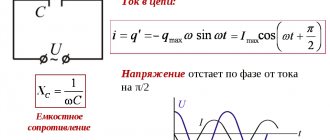
A capacitance connected to an alternating current circuit has (ideally) only reactance, the value of which is found according to the well-known formula.
In addition, we include some kind of load in our circuit (light bulb, drill, washing machine), which also has some kind of resistance R
Thus, the total resistance of the circuit will be as
Our circuit is in series, and therefore the total voltage of the circuit is the sum of the voltages on the capacitor and on the load
Using Ohm's law, we calculate the current flowing in this circuit.
As you can see, knowing the parameters of the circuit, it is easy to calculate the missing values.
And remembering how power is calculated, it is easy to calculate the parameters of the capacitor based on the power consumption of the load.
Keep in mind that in such a circuit you cannot use polarized capacitors, that is, those that are included in the electronic circuit in strict accordance with the indicated polarity.
In addition, it is necessary to take into account the network frequency f . And if in Russia we have a frequency of 50Hz, then for example in America the frequency is 60Hz. This also affects the final calculations.
Calculation examples
It is necessary to power a 36W light bulb designed for a voltage of 12V. What capacity of the step-down capacitor is needed here?
If we are talking about electrical networks in Russia, then the input voltage is 220 Volts, frequency 50 Hz.
The current passing through the light bulb is 3 Amperes (36 divided by 12). Then the capacity according to the above formula will be equal to:
| The obtained parameters of the step-down capacitor |
| C = 4.334146654694E-5 Farad I = 3 Amps P = 36 Watts Ua = 220 Volts Ub = 12 Volts f = 50 Hertz |
Whatever converts the minus fifth power into micro or mimli Farads, let's use this bot and get
| The resulting conversion result |
| resulting number = 0.0433414665469 milliFarad |
| Alternative representation |
that we need a capacitor with a capacity of 43 μF.
- Resistance. Temperature dependence >>
www.abakbot.ru
Main conclusions
It is advisable to connect an LED (several diodes) with your own hands using resistors and charge storage devices if they have low power. Such light sources are intended for indication or illumination. These circuits are not suitable for high-power lamps.
If you still need to connect a small light bulb to a 220 V network, it is important to correctly select the parameters of all elements. High AC voltage quickly destroys those that are unable to pass reverse current. The key to success is limiting the amplitude and correctly determining the depreciation reserve. The quality of diodes and other parts is also important.