Lighting devices in most cases are powered from a 220 V household electrical network. Of the alternative options, perhaps only lighting devices connected to the on-board network of cars or motorcycles can be mentioned. In other cases, at the beginning of the LED strip power supply circuit there is always a 220-volt alternating voltage source, be it a household outlet or a distribution board. In practice, there are various options for connecting LED lamps, which depend on the parameters of the lighting device.
What is needed for installation and installation of LED strip
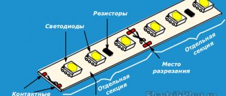
To mount and install the LED strip, you need a working LED board with the correct technical characteristics:
- Length. The standard length of a board in a reel is 5 meters, but the maximum length of parallel connected sections is 15 meters. At the greatest length, distant sections have dimmer light and a high probability of conductor wear.
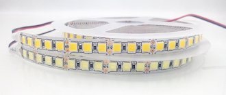
- The density indicator characterizes the number of diodes installed on 1 meter of the board. For example, 30, 60 or 120 diodes per 1 meter.
Density of diodes on the board
The power consumption, load current and supply voltage depend on the density of the crystals.
- Particle and moisture protection (IP) rating. The parameter ranges from 00 (no protection) to 68 (complete isolation). Thus, SDLs with IP20 are used indoors, for example, for interior lighting of furniture, and with IP67 - for external lighting of buildings, swimming pools and inside saunas/baths.
Particle and Moisture Protection Table
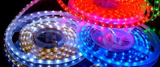
- Light flux color (monotonous/one-color or multi-color RGB strip).
Characteristics of RGB strip
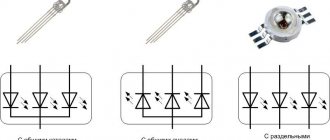
- Supply voltage. The board consists of groups of series-connected crystals that are connected in parallel to each other. Each crystal receives a supply voltage of no more than 3.3 Volts. Thus, knowing the density of the crystals, a supply voltage of 12 or 24 Volts is supplied to the board.
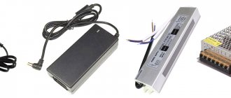
A special transformer installed between the SDL and the AC voltage source is responsible for building the required voltage level in the board. It supplies the required amount of electric current.
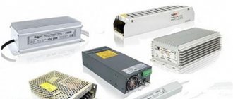
power unit
- Length of the supply cable line. The main rule is that the voltage drop of the supply cable should not exceed 8%. To do this, you need to calculate the load level and select a cable with the appropriate cross-section.
Permissible continuous current for wires and cords with rubber and polyvinyl chloride insulation with copper conductors
LED strip power calculation
The power consumption indicator directly depends on the density of crystals on the board:
| Density, pcs | Power consumption per 1 meter, W | Total power, W |
| 30 | 2,4 | The product of power consumption per 1 meter and the length of the board. For example, for a 3-meter tape with a density of 60, the power will be: 4.8*3=14.4 W. |
| 60 | 4,8 | |
| 120 | 9,6 | |
| 240 | 19,2 |
To select a power supply, the power value is 20 - 30% more than the power consumed by the board. For example:
LED strip with a density of 120 crystals per 1 meter. The total length of the SDL is 11 meters. Power consumption will be:
Plen = 9.6 * 11 = 105.6 W.
Pblock = 105.6 * 1.25 = 132 W.
Thus, the block with the closest power value is selected, this is 135 W. If you select a block with a power lower than the value that the board consumes, the latter will not light up. And the absence of a power reserve of 20-30% will lead to failure of the unit .
Option to connect directly to 220V
In addition to the canonical options for connecting to a 220V network, there is a way to connect an LED strip without using power supplies. It is based on the principle of cross-assembly of LED groups, in which the influence of a 220-volt mains current does not affect the performance of the pair.
To do this, you need to divide the whole tape into separate minimum sections. Taking into account that one such segment consumes 12 Volts, a value of 220V can be achieved by including at least 20 elements (12 V x 20 pieces = 240 Volts). Each section is connected to its neighbor according to the principle of reverse polarity: “+” to “–”.
The main disadvantages of this scheme are the possibility of breakdown of contacts, as well as visible flickering of diodes with a frequency of 50 Hz. To eliminate voltage surges, you need to organize the inclusion of a diode bridge (rectifier) and a capacitor (eliminates flicker) in the power circuit. You can also include a motion sensor here, which is powered by standard mains voltage.
Features of installing LED strip
The process of installing the SDL does not require special professional skills, however, for its proper condition, you must follow the rules.
Installation occurs in several main steps:
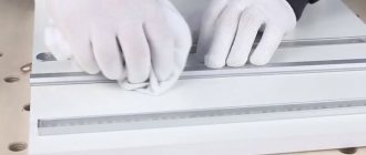
- Preparation of SDL sites. The board is measured and cut in specially designated places.
Preparation of SDL sites
- Connecting board sections to each other. By soldering (a more reliable method) and using a connector.
Board connection methods (soldering and connector)
- Connecting a power supply or adapter.
How to connect the power supply and adapter
- Connecting a dimmer (controller) responsible for adjusting the light flux.
Example of connecting an RGB controller
Why do you need a power supply and controller?
The LED strip power supply is a device in the form of an aluminum/plastic/metal case, with terminals located on both sides.
Purpose: conversion of alternating electrical voltage of the network 220 V (input terminals) into direct voltage 12/24 V (output terminals), required for proper operation of the SDL.
A controller is a device that regulates the intensity of the glow of each diode, the total mixing of which produces a certain shade and brightness of the glow of the tape.
The controller can be controlled using the program embedded in it and/or manually - from the control panel.
When choosing a power supply and controller, it is important to calculate their power consumption, taking into account a 20-30% reserve.
Low voltage tape
If, due to local conditions, it is impossible to use a 220-volt lamp, you will have to use strips with a voltage of 5/12/24/36 volts. And here there are various options for connecting to a household network.
Correct connection of two or more consumers.
Types of LED strip installation
LED strip installation is possible in several ways:
Aluminum profile. Its structure is pre-installed along the marked path, then a board with an adhesive base is glued into the channel itself. Afterwards, the entire structure is covered with a plastic profile, which creates a uniform dispersion of light.
The process of installing SDL using an aluminum profile
Pros : used for long high-power boards (more than 14 W); aluminum removes heat, thereby preventing the crystals from overheating, unlike plastic channels; smooth base and neat appearance.
Cons : higher price and time spent on profile installation.
Aluminum tape. It is attached along the intended path for attaching the board, then glue is applied to it, onto which the SDL is attached.
Pros : removes heat, ease of operation, used for small and medium power boards.
Minus : appearance.
Other fastening methods: plastic clamps, nylon ties, mounting clips.
These methods are applicable when the SDL is located in an invisible place, because visual perception deteriorates.
Double-sided tape and/or glue. One of the simple and reliable methods.
In all of these methods, the SDL is attached only along a straight path; if there are turns or corners, it is necessary to cut it and connect it using soldering or a connector.
How to glue LED strip
- Prepare the surface: smooth out any bumps, depressions, cracks, clean and degrease. Metal and plastic surfaces are degreased with acetone or white spirit; painted with vinegar. Wooden surfaces must also be varnished or painted.
- On the prepared surface, a marking (trajectory) of the SDL fastening is applied in a straight line.
- Stick the SDL using a convenient method:
- 3M double-sided acrylic tape is usually applied to the back of the board. Gradually opening the adhesive side, it is pressed tightly against the treated surface.
Fastening the tape with double-sided tape (self-adhesive base)
- Glue (super glue, instant installation, liquid nails). It is applied along the trajectory in small portions every 5 – 10 cm. Then the SDL is pressed tightly and fixed.
Pros: quick contact and grip.
Minus : lack of heat dissipation properties, which leads to overheating of the crystals.
Tape cutting and joining
Tape cutting is necessary in the following cases:
- level changes (corners, turns);
- shortening to the required length.
Cutting is carried out with scissors in the location indicated on the board (dotted tape and/or scissors icon). A cut in the wrong place will disrupt the nutritional pattern.
Place of cut designation on various tapes
To connect/extend/extend the SDL, two main methods are used: soldering or a connector (section “Connecting power using an LED connector”, “Connecting power using soldering”).
Network connection
To assemble the circuit, you need to do the following:
- cut the tape to the required length;
- if necessary, connect several sections using feed-through connectors;
- connect the diode bridge;
- connect the cable with the plug;
- connect to the network.
An RGB controller will be added to the above if you have the appropriate model.
Advice! When installing the LED strip, do not bend it sharply to avoid damage. Coat joints and cuts with sealant to protect against moisture. To avoid energy losses and unnecessary heating, a low-power strip (for example, from 3528 LEDs) can be connected in a line no more than 100 m long. If the tape is powerful (5730) - 40 m.
Recommendations for placement of equipment and installation of LED strip
- Determine for yourself the method of installing the SDL. This is important when choosing it, because Not all SDLs are equipped with self-adhesive tape. In this case, they are attached to brackets and clamps.
- Carefully prepare the surface on which the tape will be applied. For more reliable fixation, additionally cover the entire path with double-sided or aluminum tape and apply instant glue.
- During the gluing process, the protective coating of the self-adhesive layer is removed gradually as it progresses.
- In order to save money, the plastic profile of aluminum channels can be replaced with a plastic corner. It is attached with glue/liquid nails.
- When designing ceiling lighting, remember the degree of light dispersion. For the most effective lighting, the distance from the ceiling to the mounting location of the board should be at least 80 mm.
- To illuminate signs, display cases, and cabinet shelves, choose side-illuminated SDLs. This will help avoid being blinded by crystals and highlight the required interior details.
- Boards longer than 5 meters are connected to the power source in parallel. Otherwise, it will lead to damage to the diodes.
- PSUs equipped with a fan have a specific sound. Therefore, it is worth considering the location of its installation outside recreation areas. The controller, on the contrary, should be located nearby for ease of control from the remote control or manually.
- Choose trusted manufacturing plants. This will help you avoid unnecessary expenses.
Selecting adapter performance
The description of each tape contains technical data. The voltage that must be supplied (12 or 24 V) and the current consumption must be indicated there. But the current is usually indicated per 1 meter of tape. If you connect 5 meters, then you will need to multiply this figure by 5. If you connect 10 meters to this power supply, multiply by 10, etc.
If you are still figuring out how much the backlight will cost you and you don’t have a ribbon yet or haven’t chosen it yet, you can use the average data. The current consumption of the most common type of monochrome tapes is shown in the table. They can be taken as an example.
Current consumed by SMD3528 and SMD5050 LED strips depending on the number of LEDs per meter of length
The resulting figure is the minimum current value that the desired power supply should produce. But constant operation at the limit of capabilities greatly reduces the service life of electrical products. Therefore, we add 20-25% of the reserve to the found figure (multiply by 1.2 or 1.25), round the resulting figure up to the nearest whole number. This will be the current that the adapter should produce.
To make it clearer, let's give an example. Let a meter of tape consume 0.8 A, we will connect 18 meters to the adapter. We are looking for the total current consumption: 0.8 A * 18 = 14.4 A. We add a reserve: 14.4 A * 1.2 = 17.28 A. So, we will look for an adapter that will produce at least 17 Amperes.
In the case of color RGB LED strips, the current required by the controller (dimmer) and amplifiers (if they are powered from this source) is added to the found figure. This data is in the technical description of the devices.
Basic errors in connecting tapes
Mistake No. 1 – the security level of the tape is not selected correctly. For example, the use of boards with an IP20 rating is unacceptable in rooms with high humidity and in open spaces. When used in baths and bathrooms, a short circuit and electric shock may occur to a person.
Error No. 2 – the power of the power supply is not calculated correctly. It is important to follow the rule of 30% power reserve. This will allow in the future to connect additional sections or replace them with more powerful ones.
Mistake #3 – sequential connection of new sections. As mentioned above, each new tape is connected in parallel to the power source.
Error No. 4 – lack of heat sink elements. Tapes with a power of over 14 W are installed only on an aluminum profile, SDL with a power of 6 to 14 W are installed on metal tape. They perform the function of transferring heat from heating the crystals to the external environment.
Incorrect connection
Diagram of incorrect serial connection of two LED sections:
Diagram of incorrect (serial) connection of two tapes
The connection in series leads to an uneven glow of the tracks and overheating of the beginning of the tape. Therefore, each section longer than 5 meters is connected in parallel :
Example of parallel connection with 1 block and two
When the power of the tape section is above 9.6 V, it is recommended to make a parallel connection on both sides of the section. This guarantees a stable, uniform light output.
Example of two-way connection of a section
Incorrect mounting (location)
When installing, pay attention to the external environment. There should be no devices or factors nearby (within at least 0.6 m) that cause additional heating of the elements (heating system, incandescent lamps, kitchen heating appliances, sunlight, etc.). Optimal operating temperature is +40 0C.
The path for laying the SDL must be cleared of unnecessary objects. During operation, the board should not touch additional objects or have unnatural corners or bends (unless they are made by soldering or a connector).
Continuity of a separate LED in the strip
Even the burnout of one LED can cause the inoperability of an entire section of the strip or the entire backlight.
For example, this often happens in LED garlands.
In it, all the LEDs are connected in series, and shorting one bulb leads to breakdown of the entire product or a separate branch.
The LEDs are checked with a multimeter in the “diode test” mode. Look for a special icon on the case.
If you touch the contact legs with the multimeter probes, observing the polarity, the working LED should light up slightly.
Checking an LED with a multimeter Checking an LED with a multimeter
Even if the glow is not visible, you can check the serviceability of the element according to the readings on the display. It should display a number indicating the magnitude of the voltage drop.
In this case, you do not necessarily need to know the reference data of the tape. Just memorize the numbers and do the same measurements on neighboring LEDs.
Is it possible to test an SMD diode on sealed tapes with silicone protection IP65 without removing the insulation layer? Yes, you can. To do this, slightly upgrade the measuring probes by using ordinary needles.
How to do this is described in the article about repairing garlands.
By the way, breakdown most often occurs due to overheating. The reasons for it are different:
installation of LED strips with a power of more than 10W per meter without an aluminum profile
too dense installation, when individual areas of the backlight are located close to each other
installation in places with high temperatures (near heating appliances or directly above the stove)
If you mix up and connect the probes with reverse polarity, then the multimeter screen should show “infinity” or the unit “1” in the left corner of the display.
When, with reverse polarity, not “one” appears, but some other numbers, this also indicates the presence of a malfunction. This LED needs to be changed.
Remember, to make sure the LEDs on the strip are working, you need to check them in both directions!
When a faulty element is found, replacing it will not be easy for a non-professional. But you can do it differently.
Simply cut out the faulty section of the LED strip on both sides in special places for cutting.
And instead of it, through connectors or soldering, you connect another one of the same type.
Safety precautions
- All installation work is carried out with the power turned off.
- When installing the SDL on a conductive surface, the attachment point is pre-insulated.
- Observe polarity when connecting contacts; multi-colored conductors help with this.
- Do not touch exposed conductive parts while the power is on.
- Do not expose the board to mechanical stress (kinks).
- Follow electrical safety rules when working with 220 V networks.
- Related Posts
- Incandescent lamp: characteristics and features.
- How to repair an LED strip, why it stopped lighting
- IZU: connection diagram, types, which one to choose
Circuit assembly process
In order to connect an LED strip to 220 V, you will need the LED strips themselves, a power supply, a controller (if needed), wires of the required colors and lengths. The wires are preferably stranded copper (they are softer, but harder to solder) or made from a single wire. Take colored wires, this will make it easier to correctly connect the LED strip to 220 V.
The following tools will also be needed:
- scissors;
- heat-shrink tubing;
- soldering iron with rosin and tin (selection and use of a soldering iron).
Scissors are needed if you need to cut a piece from a reel of LED strip. You can only cut in certain places. On the tape they are indicated by a vertical line, next to which there is usually a schematic image of scissors. Another distinctive feature is the solder pads, which are located on both sides of the cut line.
LED strips need to be cut only in certain places
Next, we take the wires, strip their ends of insulation (2-3 mm), and tin them. and put on the prepared wire a piece of heat-shrinkable tubing of such a size that it would fit onto the tape in its original state. Next, use cotton wool soaked in alcohol to clean the contact pads, tin them (dip a heated soldering iron into rosin, heat the pad for a couple of seconds. It should be covered with a thin layer of tin. Solder the wires to the prepared pads. Be careful and do not take a lot of tin when soldering. The pads are located very close by planting a tin blot, it is easy to connect them (especially in colored ribbons).
After all the wires are soldered, lower the heat-shrink tube so that it covers all the contacts and warm it up. By shrinking, it will close all contacts well. In general, it is better to carry out this operation after checking the functionality of the circuit. If everything lights up and glows, you can isolate it.
Simply press between two plates
Having soldered the wires to the tape, we connect them to the output of the adapter or controller. Everything is simple here. There is a clamping screw and contact plates. We loosen the screw, insert the bare wire (3-4 mm) between the plates, and tighten the screw. We lightly tug the wire a couple of times, checking the contact - if it holds, then everything is fine.