Next, the circuit operates according to an algorithm depending on the direction of rotation of the motor.
Electric motor connection diagram We will talk about connecting an asynchronous electric motor when connecting the windings with a star or delta in the V network. We hope that our instructions for connecting a magnetic starter with diagrams and detailed video examples were clear and useful for you! If the magnetic action is not observed when the START button is released, the contacts are not fixed, but fall off, therefore, the whole point is in their incorrect connection. A coil with calculated volts is connected to the terminals between ground and phase. Connection diagrams for a magnetic starter (contactor) - Operating principle The general parameters of the coil are fully consistent with the technical characteristics of the starting devices. The faster the opening occurs, the smaller the arc and the better condition the contacts themselves will be.
Each pair has both mobile and fixed contacts connected to the terminals located on the body via metal plates.
The diagram shows that starter coil 5 is powered from phases L1 and L2 at voltage V.
The location of additional contacts determines the difference between a contactor and a magnetic starter. The device will work reliably if its installation location is on a straight, flat, and vertical surface.
Connection Instructions The easiest connection option is via a button. Therefore, after the contactor has tripped, it can be released.
Connection and connection of the starter (contactor)
Difference between contactor and magnetic starter
Many people confuse contactors with starters. How do they differ from each other?
A contactor is essentially a single device designed to close and open electrical circuits. And the starter is a kind of complex device that performs the same function, but with additional elements in its circuit.
For example, various types of protection or trigger buttons.
The big problem is that many people use these terms differently.
The main thing is to understand the functionality of each equipment.
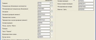
What do the abbreviated names of starters mean?
Below are explanations of the symbols and names of popular brands of starters and contactors PML, KME, PAE, PMA.
From them you can find out what certain alphanumeric symbols mean and how they are deciphered.
It turns out that just from the name alone you can understand:
- what product is this
- what functionality does it have?
- what additional capabilities does it contain?
To view each starter type, click on the appropriate tab.
PMLKMEPAEPMA
However, in addition to the name, a lot of information is contained on the contactor body itself.
Let's look at the example of two products from IEK KMI and Schneider Electric LC1D25, what inscriptions and designations manufacturers put on the housings, how they are deciphered and what they mean.
Technical specifications on the contactor itself
Let's start with the contactor from Schneider Electric. The maximum possible power connected to the contactor in horsepower (HP) is indicated on the side edge. This power depends on the supply voltage.
In a number of countries, horsepower is still used, although there are recommendations from the international metrology organization that horsepower should be eliminated from use.
The following are general recommendations for selecting circuit breakers or fuses.
- the inscription CB - Circuit Breaker refers to automatic machines
- Fuse – to fuses
The maximum operating voltage (a.c. max) must be specified.
Cont. current is the continuous rated current at load category AC1.
To put it simply, category AC1 is a load such as an iron or an ordinary heater.
AWG 6-14 Cu - shows the cross-section of wires that can be connected to the contacts.
Measurements are in Western units. In order to find out the analogue of our section in mm2, you will need to use the AWG to mm2 conversion table.
Torque 20lb.in – the torque with which the terminals can be tightened.
More accurate numbers in conventional units of measurement can also be found in the technical data on the manufacturer’s website, or use a special program here that converts lb-in to Nm (newton meters).
Lb-in stands for pounds per square inch.
High-quality contactors always have inscriptions indicating the presence of certificates to which this mechanism corresponds.
Ith-40A – conditional thermal current in open design. Simply put, this is the current that the contactor can pass through itself under normal environmental conditions.
Ui=690V – rated insulation voltage of the product.
IEC/EN 60947-4-1 – starter compliance with this standard. GOST R50030.4.1-2012 is our modified analogue of this standard.
Uimp=6kV – permissible pulse overvoltage.
A separate plate indicates the possible powers connected to the contactor, depending on the supply voltage.
Powers are already registered in kilowatts. Some may wonder why there is such a difference depending on the voltage.
This is explained simply. By and large, the contactor does not care what voltage the load is designed for. The most important thing is the amount of current flowing through its contacts.
For example, you have a voltage of 100V and a current of 10A. The load in this case will be 1 kW.
And if the voltage is 2 times greater, i.e. 200V, then when connecting the same load of 1 kW, a current will flow through the product 2 times less than I = 5A.
Therefore, the lower the voltage, the less power the load can be connected to the contactor. At the same time, always pay attention to what type of load the data is indicated for.
For example, in this case, the powers are indicated for the AC3 load. An example of such a load is an asynchronous motor.
JIS C8201-4-1 is a Japanese industrial standard. Accordingly, the possible powers connected to the contactor are also specified here, depending on the supply voltage according to this standard.
Why is such a large and strange set of voltages prescribed? Because different countries have different standards that determine power voltage levels.
For example, in Japan, a regular outlet has 100 volts. And for powerful loads, 200V is already used.
Basic device
It is used in cases where it is necessary to carry out normal starting of an electric motor. But we know that the starting current of the engine is much higher than the operating current, which means that an ordinary household machine with a current of 3A will operate immediately when such an engine is started. The wires in the wiring diagram also need to be routed correctly. Switching on a three-phase electric motor with a thermal relay through a push-button post looks like this: In the end, it looks something like this, in the picture: If you want to connect a three-phase motor through a magnetic starter with a volt coil, you need to perform the switching according to the following wiring diagram: Using three buttons on The control panel can organize reverse rotation of the electric motor. If this does not happen, you should check the position of the contacts at the STOP button, which should be in a closed state. An electromagnet in the form of a coil with a large number of turns is designed for a voltage of 24 V.
Connecting the trigger mechanism to the electrical network at volts, fig. Copper wires must be tinned before connection. Typically the circuit is used with an asynchronous motor.
It includes two pairs of contact groups consisting of normally closed and normally open contacts. The diagram shows that starter coil 5 is powered from phases L1 and L2 at voltage V. How to connect a thermal relay?
The operation of an MF is based on the effect of the appearance of a magnetic field when current penetrates through an induction load, that is, through a coil. This is an extremely simple scheme. Magnetic starter connection diagram.
Contact labels
Let's move on to the inscriptions on the front panel of the starter = contactor.
A1 and A2 are the control coil connection points.
The terminals themselves are marked in two alternative ways:
- number sequence 1-2-3-4-5-6
- alphanumeric. Top L1-L2-L3. Bottom T1-T2-T3.
Auxiliary contacts are marked in accordance with standards. There is one nuance that not everyone knows about.
Modular contactor
An ABB contactor is a device whose contacts are closed or opened by a coil (electromagnet). Voltage was applied to the coil (electromagnet), and the contacts of the contactor itself, depending on its design, either closed or opened. The contactor coils are designed for both alternating current (AC) and direct current (DC), so when choosing a contactor, pay attention to this parameter. The voltage can be connected from 12 to 415 V, you must also pay attention to this, because a modular contactor designed for a voltage of 12V will simply burn out when 220V is applied to it.
ABB modular contactors are divided into two series: ESB and EN. The difference is that ESB contactors are controlled only by supplying or turning off voltage and are designed for currents of 20, 24, 40 and 63A, while EN contactors have additional manual control (on/off) and are designed for currents up to 40A.
Contactors have
two types of contacts . Some contacts are power contacts that open or close power circuits, and others are control contacts for the contactor itself, i.e. directly give a command to close/open the power ones.
Control contacts A1-A2 are designated the same on all contactors. It is to them that voltage must be applied or removed so that the power contacts open or close.
Power contacts that turn on or off the load connected to the contactor are always in pairs 1-2, 3-4, 5-6, 7-8 , etc.
The number of pairs of power contacts for ABB magnetic starters is even, either two or four. They are designated either NO (normally open) or NC (normally closed). Those. when there is no voltage on the NO coil, they are open; when voltage is applied to the NO coil, they are closed, and NC, accordingly, is the opposite. There are different variations: 2NO (two open contacts), 3NO-1NC (three open + one closed), etc., and are indicated on the contactor body by the numbers 40 (four NO contacts), 20 (two NO contacts), 22 (two NO and two NC), 02 (two NC).
the ABB EN40-40N contactor it follows that this modular contactor is designed for a rated current of 40A and has four NO (normally open) contacts . It is also stated that the contactor coil is designed for 230V AC or DC.
To protect the contactor control coil, it is correct to install a circuit breaker in its circuit, etc. The power consumed by the coil is negligible, so it is better to take the rating of the machine no more than 1A.
The ESB 20A contactor occupies 1 module, 24A - 2 modules, 40 and 63A - 3 modules each on a DIN rail.
Contactors are also available with manual control, or more precisely with combined control. Those. You can use the switch to turn the modular contactor on and off with your hands by moving the lever. The photo below shows an ABB EN-40-4NO contactor with manual control.
Contactors, as well as other modular devices of the leading series ABB, Legrand, Schneider Electric, Hager, can have an additional contact . Just keep in mind that these are “not entirely full-fledged” contacts; they have a rated current of only up to 6A .
Below is an example of an additional contact for a Legrand contactor. The auxiliary contact actually has two contacts, one NC and one NO.
Connecting the modular contactor and the auxiliary contact is easy. The connection diagram between the devices is shown on the additional contact itself. It is important that the hole in the contactor and the “lever” of the auxiliary contact align exactly.
And this is what combined devices look like, including those already connected in the electrical panel.
Normally open and closed contacts
The first digit of the designation is the serial number of the contact. And the second digit is the contact function.
For example, at the top you can see the inscriptions 13-21. Bottom 14-22.
That is, the first numbers 1-2 are the serial number of the contact. There is one auxiliary contact on the left, and a second on the right.
And the second number is the function. The number 1-2 is the common wire or part of the normally closed contact of the circuit.
The number 3-4 is part of the normally open contact. That is, by looking at the numbers, without unwinding or ringing the mechanism, without studying its diagram in the passport, you can immediately understand that 13-14 is normally open contact No. 1 (NO - normal open).
A 21-22 – normally closed contact No. 2 (NC – normal closed).
All other electromagnetic relays familiar to us have the same markings, making it easier to visually understand the functionality of the device. Here is an example of another relay and the designation of its contacts.
You don’t need to look for documentation for it to understand how to connect here or what function this or that screw terminal has.
The voltage of the coil that controls the starter is also required to be written on the housing.
The letter M7 (or another) is a definition of the coil type in the order number.
For example, if a coil burns out in your LC1D25 contactor, you will only need to indicate the voltage and its number M7 when ordering. You will know for sure that exactly the product will arrive, and the size you need.
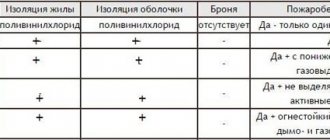
Another important point that is worth paying attention to is the possibility of using different types of wires in the terminals. If the pads are copper, this means that it is unacceptable to use aluminum wires.
The cross-section and types of connected wires are indicated in the technical documentation.
Magnetic starter connection diagram
They supply voltage to the coil.
Basic structure The contactor consists of several units: Energy.
In this case, you need to act as shown in the video: We connect the starter through a push-button station without reversing. For an example with an engine, it looks like this: Controlling an electric motor on Volts You can connect the engine using a reversible circuit as follows: Turning on the engine through three buttons Using this principle, you can independently connect the device to the network and volts. For aluminum wires, the ends are cleaned with a file, then covered with paste or technical petroleum jelly. To prevent distortion of the spring washers located in the contact terminal of the starter, the end of the conductor is bent in a U-shape or into a ring.
Connection diagram: working or not After making all connections, it is recommended to check how the assembled starter connection diagram will function. This option provides for the supply of voltage exclusively during operation of the device. It will remain on. This field appears as a consequence of the flow of electric current through a coil with a core. It can be in or in. Coils are available from 12 to volts.
Visual diagrams of MP and CM
What does a practical wiring diagram for connecting a magnetic starter look like? If it is in, phase and zero go to the coil.
Set the core voltage designation which is mentioned on it and not on the starter. There are two types of blocking contacts: normally closed, normally open. They supply voltage to the coil. This is an important aspect, because if connected incorrectly, the core may burn out or will not fully start the necessary contactors.
Starters are often used to mechanically switch on heaters, lighting lines, etc. This means that a three-pole circuit breaker must be set to 3 or 4A. The reverse circuit involves obtaining from two contactors or magnetic starters the switching of the motor windings to change the rotation of its rotor to the opposite. The top of the relay is equipped with additional contacts integrated with the coil. Magnetic starters are installed next to each other. Reversible connection diagram for a magnetic starter