Design and principle of operation of networks with solidly grounded neutral
The operating principle of electricity sources, in particular step-down transformers, is based on the law of mutual induction and energy transfer through a magnetic core. In this case, the primary winding may not have a neutral wire, in contrast to the secondary, where connecting it to zero through a conductor with low resistance, which can be equated with a zero value, will be an effective means of protecting a person from being hit by a voltage dangerous to his life and health.
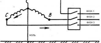
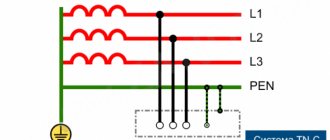
The main feature of networks with a solidly grounded neutral is the appearance of not only linear, but also phase voltage. Let's look at what it is and how it differs from each other using a simple circuit diagram as an example.
Phase voltage is the potential between one of the line wires and the zero point connected to the ground, that is, tightly grounded. Line voltage is the potential difference between the two terminals of the lines, that is, L1 and L2, L1-L3, or L2-L3, it is also called phase-to-phase. Such sources of electrical energy in domestic conditions have a common voltage value in the form of 380 V - linear, and 220 - phase. Line voltage is greater than phase voltage by √3, that is, by 1.72.
But the main task of such a system is not only to transport voltages of two values to consumers with different numbers of phases in one power supply system, but also to protect people in the event of insulation breakdown and the appearance of voltage at points that normally do not have a dangerous potential. In residential buildings this is:
- the housings of all household appliances that conduct electric current, that is, made of steel or other conductive metal;
- metal structures of switchboard and distribution devices;
- protective sheath of cables.
Also, to ensure safety, all of the above elements must be grounded; in this case, the danger from the use of voltage and the use of household appliances in networks with a solidly grounded neutral will be minimal. Moreover, for such circuits, uniform distribution of single-phase loads is required.
Technical features
In this system, where a common midpoint is used, in addition to the phase-to-phase voltage, there is also a phase-to-phase voltage. The latter is formed between the working zero and the linear wires. The difference between the first and the second is clearly demonstrated below.
The potential difference UF1, UF2 and UF3 is usually called phase, and the values UL1, UL2 and UL3 are called linear or interphase. It is characteristic that UL exceeds UF by approximately 1.72 times.
What kind of lighting do you prefer?
Built-in Chandelier
In an ideally balanced three-phase electric current network, the following relationships must be maintained:
In practice, it is impossible to achieve such a result for a number of reasons, for example due to uneven load, leakage currents, poor insulation of phase conductors, etc. When the neutral is grounded, the imbalance of the linear and phase characteristics of the power system is significantly reduced, that is, the working zero allows potentials to be equalized.
Expert opinion
It-Technology, Electrical power and electronics specialist
Ask questions to the “Specialist for modernization of energy generation systems”
Question No. 5. Definitions: solidly grounded neutral; insulated neutral, conductive part (PUE, clauses 1.7.5 - 1.7.7) - Studiopedia A three-phase electrical network, which is widely used for power supply, uses two main connection options: triangle and star. Ask, I'm in touch!
Explanation for dummies
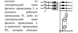
The step-down substation in which the transformer is installed has its own ground loop. It is interconnected by steel tires and rods into one grounding circuit. A cable containing four cores is laid to consumers in the electrical panel from the substation. If the consumer needs power from a three-phase 380 Volt circuit, then it must be connected to all conductors. In a single-phase 220 V network, power will be supplied from the neutral wire and from one of the phases. The protection of people in single-phase and three-phase circuits, if there is no grounding system, should be carried out using special residual current devices (RCDs), which are triggered by a small leakage to zero, while reliably disconnecting the consumer from the network.
Functions
In an ideal situation, zero should act as a conductor, ensuring the closure of the electrical circuit. But in fact, the voltage across phases often differs significantly.
Also read: Are LED lamps harmful to human health?
As the power increases in one of the phases, the current decreases and the zero shifts, producing a bias voltage. This characteristic is directly proportional to the difference in phase voltage. As a result, some consumers are supplied with increased voltage, and others with reduced voltage.
The purpose of the neutral wire is to equalize the voltage between phases so that consumers are supplied with current with standard characteristics.
If the voltage increases for one phase, the excess through zero at the substation moves to another phase, leveling the indicators.
Classification of networks with solidly grounded neutral
A modern power supply system has a standard marking where, in addition to the working neutral conductor, there is also a protective one, which determines the degree of protection.
- L - phase conductor;
- N—working zero;
- PE - protective neutral conductor;
- PEN - the working and neutral conductors are made of one wire.
There are several subsystems in circuits with an energy source that has a solidly grounded neutral:
- TN-C. With this system, the neutral and protective conductor from the substation are organized by one conductor; near the receiver, its housing (or other elements to be grounded) is connected to this combined conductor - this is called grounding. This is an outdated system, it was used in old houses during the USSR, but now it is not used for household consumers, as it is unsafe. Such a system has a significant drawback, since if the PEN conductor breaks on the path from the supply transformer to the power receiver, a dangerous potential appears on the grounded equipment housings. Used only to protect industrial consumers (discussed below in the next section).
- TN-S. Has a greater percentage of safety during emergency situations. This is achieved by separating the protective and working conductors along the entire length of the supply line, from the transformer to the electrical distribution panel (to the end consumer). However, due to the fact that it is necessary to use cable products with five cores, which greatly increases the cost of installation and the budget for organizing power supply to the consumer, this system is not always used.
- TN-CS. This grounding system is the most common in our time. With this system, the neutral and protective conductors along the entire length of the line are combined into one combined conductor PEN. At the entrance to the building, this conductor is divided into protective PE and zero N, which are then distributed to consumers (apartments). With this system, if the PEN conductor burns out to the separation point, a dangerous potential will appear on the grounded housings of electrical appliances. To prevent this, repeated grounding of the PEN conductor is made along the entire length of the line and at the entrance to the building and increased requirements are imposed on the mechanical protection of this conductor.
- TT. This grounding system is practiced if the TN-CS system line is in unsatisfactory technical condition and the protective grounding provided in it does not provide sufficient safety. This grounding system provides for the installation of an individual grounding loop at the consumer, while the PEN conductor of the electrical network is used only as the neutral wire N.
Designations in grounding systems
The system designations use Latin letters:
- T (ground);
- N (neutral or functional zero);
- I (isolated);
- C (connection of protective and functional “zero”);
- S (separate application of protective and functional “zero” throughout the entire network).
In system designations, the first letter determines the type of grounding of the power source, the second letter indicates the type of grounding of the open components of the electrical receiver.
Properly designed and implemented grounding is one of the basic conditions for ensuring electrical safety of facilities where household or industrial electrical equipment is operated. When performing grounding, you must be guided by the requirements of the PUE (Electrical Installation Rules).
Invite to tender
If you have a tender and need more participants:
Select from the list the type of work that interests youIndustrial safety auditIdentification and classification of hazardous production facilities, obtaining a license to operate hazardous production facilitiesDevelopment of plans, action plans, documentation related to the readiness of enterprises for civil emergency situations and fire safetyInspection and examination of the industrial safety of buildings and structuresWork on lifting structuresWork on boiler inspection and power equipment facilitiesWorks at gas supervision facilities Work at chemical and petrochemical facilities Work at facilities related to the transportation of hazardous substances Work at production facilities for the storage and processing of plant raw materials Work at metallurgical foundries Work at mining plants Conformity assessment of elevators, technical examination of elevators Development of a safety justification for a hazardous production facility Development of documentation for an industrial safety management system Development of industrial safety declarations securityWork at the facilities of the Ministry of Defense (special purpose production of military units) and the facilities of the Federal Penitentiary Service of Russia (special purpose organization of correctional institutions) Design Repair and installation work Repair of automobile lifting equipment Electrical repair and electrical measuring work Development and production of safety devices for industrial facilities Development and production of non-standard metal products and equipment Non-state examination of design documentation (engineering surveys) Pre-certification training according to safety rules and standards Vocational training (blue-collar professions) Training in labor protection, fire safety and electrical safety, heat power engineering Special assessment of working conditions (SOUT) (until 2014 certification of workplaces)Accreditation and certification in the industrial safety examination systemCertification of equipment, declaration of conformityEnergy auditDevelopment of heat supply and water supply schemesOther workAdvanced training, professional retrainingInspection of shelvingCopy the link to your tender into this field, to do this, go to the browser, open your site, highlight and copy the address line, then paste into this field. If it doesn’t work out, just write the tender number and the name of the site. personal data
Types of connection of power transformer windings
As noted above, neutral is the connection of the neutral conductor of a three-phase power transformer or generator. To determine the type of grounding, just look at the diagram of the power equipment. For an isolated neutral, the circuit diagram is a triangle.
The remaining options are implemented through grounding the neutral conductor to ground, DGK, and a low-resistance resistor. The latter are mainly used at substations that convert high voltage electrical energy to low voltage for consumer use. The schematic diagram is a star.
It is important to know
The advantage of such a system is the cost savings on protective grounding wiring, as well as the reduction in the cost of cable products, since single-phase and three-phase electrical receivers can be connected to the same circuit.
Modern power supply is still aimed more at safety, and therefore requires the installation of an RCD and a separate protective grounding circuit, through which even the smallest leakage currents will go into the ground, without endangering a person.
Now you know what a solidly grounded neutral is, what its operating principle is and in what networks it is used. If you have any questions, you can ask them in the comments below the article!
Expert opinion
It-Technology, Electrical power and electronics specialist
Ask questions to the “Specialist for modernization of energy generation systems”
Isolated neutral: what is it and where is it used A little about the use of the grounding method with a solidly grounded neutral; it is not chosen for creating underground or overhead medium voltage networks in Europe, but is actively used in distribution networks of North American facilities. Ask, I'm in touch!
PUE requirements
In the Rules, Chapter 1.7 is devoted to the standards and requirements for solidly grounded systems; we present the most significant excerpts from it:
- To connect the neutral to the ground loop, you must use a special conductor.
- When choosing a location for a grounding device, you should proceed from the minimum permissible distance between it and the neutral.
- If a reinforced concrete foundation structure is used as grounding, then it should be connected to its reinforcing base at at least 2 points, this guarantees the most effective protection.
- The resistance of the grounding conductor for a three-phase electrical network circuit of 0.4 kV is limited to 4 Ohms. In exceptional cases, this standard may be revised based on the characteristics of the soil.
- It is prohibited to install fuses, protective devices and other elements that could compromise the integrity of the conductor in a solidly grounded neutral line.
- The rules require that the grounding conductor be provided with reliable protection from mechanical damage.
- The overhead line must be equipped with redundant grounding switches; they are installed at the beginning and end of the line, on branches, and also every 200 m.
- Duplicate grounding must also be carried out at the consumer input and must be indicated in the ASU panel diagram.
- When organizing household single-phase networks from the ASU, wiring must be carried out with three wires, one of which is phase, the second is zero (N) and the third is protective (PE).
- The response speed of circuit breakers installed in single-phase networks with a solidly grounded neutral should not last longer than 0.40 seconds.
