What it is
The main feature of the TN-C grounding system is the absence of a separate grounding conductor (N), which in this system is combined into a single whole with the neutral working conductor (PE). That is, in a power supply circuit using the TN-C system, the neutral conductor is connected to the grounding loop of the transformer substation and approaches the consumers' electrical receivers with one wire, which is both the neutral working and protective conductor (PEN).
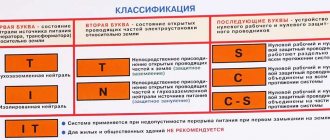
Decoding of the TN-C grounding system according to a unified standard for classifying grounding systems developed by the International Electrotechnical Company: T (terre) - grounded, N (neuter) - connected to the source neutral (zeroed), C (combined) - combined.
Thus, a single-phase power supply circuit when using this grounding system is two-wire: phase and zero, and a three-phase four-wire: three phases and zero - there is no separate grounding conductor. (For comparison: the more advanced TN-CS protective grounding system, which is also used in everyday life, has the following circuits: single-phase circuit - three-wire: phase-neutral-ground, three-phase circuit: three phase-neutral-ground.)
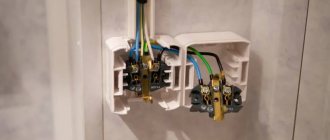
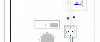
It is very simple to independently determine the presence of this system in a residential building or apartment - you need to see, firstly, what sockets are installed in the premises: ordinary or “euro” (with a third grounding contact), and secondly, whether this grounding contact is connected to the third wire electrical network.
It is not allowed to use a PEN conductor as a grounding conductor for electrical appliances and electrical equipment.
System with earthed CT neutral
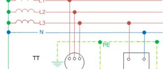
CT is a system where the neutral belonging to the power source is solidly grounded, but the exposed conductive parts are grounded separately, using a special grounding device that is electrically independent of the neutral.
TT stands for:
T – grounded neutral, the connection of the neutral of the electrical energy source with the ground is direct;
T – exposed conductive parts are grounded. This means that grounding is carried out locally (locally) regardless of the neutral.
The diagram is shown below:
The advantage of such grounding is that the PE grounding loop is absolutely independent of the neutral wire N. If it is destroyed at the substation or on the way from the substation to the consumer, it will not affect the PE loop at all.
But there are also disadvantages, namely, a more complex lightning protection circuit is required to avoid the appearance of peaks between N and PE. Also, in this system, it is quite difficult for the circuit breaker to trace a short circuit to the frame, since with local grounding its resistance is quite high.
Moreover, the PUE recommends the TT system as an additional one, provided that the supply line cannot satisfy the TN-CS requirements for PE mechanical protection and re-grounding. Also in electrical installations in which, when touched, direct contact with the ground or with grounded metal elements is possible.
You also need to remember that when using CTs, it is necessary to use an RCD. As a rule, in such systems an input RCD is used, which has a setting of 100 - 300 mA and monitors the short circuit between the PE and the phase. After it, personal RCDs are installed for specific circuits with setting currents of 10-30 mA.
Advantages
The main and almost the only advantage of this grounding system is the exceptional cost-effectiveness of installation. (Obviously, eliminating the third grounding conductor (PE) saves materials by almost a third, which is very beneficial for the mass use of this grounding system.)
Therefore, this grounding system was widely used at one time in the Soviet Union in standard, mass developments - and most likely, Soviet engineers made this choice quite consciously: it was much more important to provide as many people as possible with electricity, even lowering the overall level of electrical safety. It should be noted that in almost all European countries, the protective grounding system, TN-CS, was initially used, although more expensive, but also more reliable from the point of view of ensuring consumer safety.
Also, as a unique advantage, the relative simplicity of converting this grounding system into a more reliable and safe TN-CS protective grounding system should be recognized. (The alteration is carried out only by adding just one wire to the network, both in single-phase and three-phase circuits.)
The use of the TN-C grounding system is expressly prohibited by the Electrical Installation Rules during reconstruction or new installation of a power supply circuit.
Protecting your home from overvoltage in the TT system
To prevent a lightning discharge from entering a building, it is necessary to use a lightning protection system, when the high energy of natural phenomena is captured by an air terminal and discharged to the ground potential through a ground loop. The latter must withstand extremely heavy loads.
When a high-voltage discharge enters the overhead power line supplying the house, its surge protectors operate. However, part of the energy in a short pulse may well penetrate the phase wire into the home electrical wiring and burn out the connected equipment.
In addition, on an overhead line, it is quite possible for the electrical wire of the working zero to break when in a three-phase system the neutral is displaced, and the phase voltage of 220 volts can increase to a linear voltage of 380.
The protection of building equipment in such situations is entrusted to surge arresters or surge protectors (pulse type) and overvoltage relays.
Flaws
The main disadvantage of this grounding system is the possibility of voltage appearing on the housings of electrical installations in the event of an accidental or emergency break of the neutral wire. (Used in this system as a working and protective neutral conductor (PEN)).
It should also be noted the following disadvantages of the TN-C system arising from the combination of the zero working (PE) and zero protective (N) conductors into a single whole:
- Impossibility of protecting people from electric shock.
- The impossibility of using a PEN conductor as a grounding conductor for electrical appliances and electrical equipment leads to the failure of electrical appliances.
Also, a rather fundamental disadvantage of using the TN-C system is the inadmissibility of potential equalization in bathrooms. (To equalize the potentials, it is necessary to reconstruct the TN-C system into a TN-CS system by adding a protective conductor.)
The main and most effective method of protection when operating circuits based on the TN-C grounding system is careful adherence to basic safety rules.
IT isolated neutral system
In IT, the neutral does not physically have contact with the ground or does, but through devices with high resistance, and the current-carrying elements of the system are grounded.
IT stands for:
I – (from English isolation) isolated neutral;
T – indicates the presence of local (local) grounding of parts of electrical installations;
In such systems, the leakage current to the frame or ground will be quite low and will not affect the operation of the equipment.
IT is used in special-purpose installations with increased requirements for reliability and safety (for example, in hospitals for emergency power supply).
Natural and artificial types of grounding
Natural grounding - structures in direct contact with the ground. The following
are used as natural protection:
- Lead sheathed cables laid in trenches underground; rail tracks of non-electrified access roads, railways, etc.
- Reinforced concrete and metal structures of any building structures that are in direct contact with the ground.
- Underground water and sewer lines. Do not use metal pipes that carry explosive or flammable substances.
Artificial grounding
As a rule, horizontal and vertical electrodes are used for artificial grounding. The role of vertical can be played by a twig or steel pipe, at least 3 meters long. The essence of the implementation is to immerse the upper ends into the ground and connect them with a strip of steel using a welding machine. This technology forms a grounding loop.
For safe use of electrical appliances, natural grounding conductors must be used. Their use allows you to save the family budget and time, since there is no need to construct artificial grounding conductors. If the natural type satisfies all the requirements of the PUE for resistance to spreading, the artificial one need not be built.
Comparison of artificial and natural contour
Pipelines located in the ground act as a natural grounding system.
A natural circuit is two or more metal structures that are in contact with the soil for the safe use of household appliances. Natural grounding is also divided into the following types:
- Pipelines intended for various purposes located in the ground.
- Reinforcement of building structures, which is immersed in soil layers.
These types of protective contour must be associated with the object by at least two elements. As a rule, they are installed in different parts of the structure.
As a natural defense, it is prohibited to use:
- heating systems and sewer lines;
- pipes whose surface is coated with an anti-corrosion compound;
Artificial ground electrode - metal structures intended for transportation of flammable and toxic substances.
An artificial contour is a special structure made of metal. To work, they are immersed in layers of soil. The most common examples of artificial protective contours are:
- Metal sheets laid in the ground. They can have different shapes and sizes.
- Rods, angles, pipes and steel beams placed in the ground.
Each element of an artificial circuit must have corrosion-resistant electrical conductors made of zinc or copper.
Requirements for the grounding device
The most important characteristic of a grounding device is its resistance. The requirement for this parameter, if grounding is performed according to the TT system, can be expressed as follows (PUE clause 1.7.59):
R ≤ 50B/Iav.uzo
In this case, in the case of using several residual current devices, the differential operating current of the device where it has the maximum value is taken into account.
In addition to this requirement, the basic system of potential equations must be met (clause 1.7.60 of the PUE). The essence of the event is to connect the following structures together:
- Grounding device made on site.
- Metal pipelines for heating, water supply (cold and hot), sewerage, gas supply.
- Metal structures related to the building frame.
- Metal parts of ventilation systems and air conditioning systems.
- A grounding device included in the lightning protection of a private home.