A generally accepted way to ensure safety when working with electrical equipment is grounding. In the PUE, in the list of measures to protect people from the effects of electric current, protective grounding comes first (clause 1.7.51, Chapter 1.7). This measure involves connecting open conductive parts of the electrical installation to a grounding device. Depending on the design features of electrical installations and networks, the grounding loop can be organized in several ways. The system in accordance with which grounding is carried out is determined at the design stage or prescribed by technical conditions issued by the electrical network organization. The subject of this article is the CT grounding system, the operating principle and scope of which will be described in detail below.
CT grounding system
The abbreviation TT means the following:
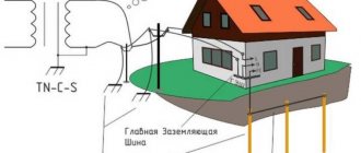
- The first letter T - the neutral of the power source is connected to the ground (T - is formed from the English word “terra”, which means “earth”. That is, this is a system with a solidly grounded neutral, just like TN.
- The second letter T - all parts of consumer electrical installations that can be exposed to life-threatening voltage are forcibly connected to the ground. But the re-grounding loop in the TT system is not electrically connected to the neutral grounding loop of the power source - generator or transformer.
Vasiliev Dmitry Petrovich
Professor of Electrical Engineering, St. Petersburg State Polytechnic University
Ask a Question
This is the significant design difference between the TT system and the TN system. In the TN-C system, the source and consumer circuits are connected to each other using a PEN conductor. In the TN-S system, a PE conductor is used for this. CTs do not have this electrical connection.
But this does not mean that there is no connection at all. The surface of the earth conducts electric current. This is the basis for the protection principles in the TN-C and TN-S systems.
Installation of accounting and security devices in the panel
Now it’s time to install all the other elements on the DIN rail. The complete list of equipment required for the panel of a private house is as follows:
1) Steel electrical panel (protection rating IP54 or higher)
2) Box/casing for AV for 3 modules
3) Three-pole circuit breaker 25A
4) Three-phase electric energy meter 380V
5) distribution block for DIN rail
6) Selective RCD from 40A, leakage current 100mA or 300mA
The electricity meter must be three-phase, for 380V networks. Usually electronic, two-tariff is chosen. When choosing a manufacturer, the main guideline is the warranty period; the one with the longest warranty should be taken. Usually a simple one is taken, without unnecessary interfaces, for example, Mercury or Energomera.
The distribution block must have a sufficient number of terminals for the required conductor cross-sections. For the option with a VDT - residual current switch, with CT grounding, you will need:
1 terminal - 16mm.kv - for re-grounding circuit PV1 or PuV (PuGV)
2 terminals of 6mm.kv - for internal conductors used for switching
The fire protection RCD is selected selective - having a delay when triggered. The leakage current can be either 100mA or 300mA.
The choice of the response threshold of the Residual Current Device depends on many factors. Almost any electrical appliance has some leakage and this is normal. If there are many such devices, the total losses can be large.
Based on this, this value is selected. If the housing is small, it is enough to set 100mA. If this is a cottage, with a lot of technology and equipment, then definitely 300mA.
For internal connections in the panel, it is most convenient to use flexible wires PuGV (also called PV-3) 1x6mm.sq. and NShVI tips.
Disadvantages of the TN system
And this is where problems arise. The line resistance from the power source to the fault is sometimes so high that ground fault currents (ground loop) only lead to the start of the thermal release. The protection works with a significant delay, and in some cases it is not able to work at all.
During this time, a person who accidentally finds himself in contact with a seemingly grounded surface is exposed to life-threatening voltage.
The second danger lies in the breakage of the protective conductors connecting the grounding circuit of the source with the enclosures protected from the occurrence of dangerous potentials. In this case, what is intended to protect becomes even more dangerous. If there is no damage to the electrical installation, all its grounded parts are energized. If the re-grounding circuit is absent or insufficiently effective, the likelihood of electric shock to a person rapidly increases.
Orlov Anatoly Vladimirovich
Head of the Relay Protection and Automation Service of Novgorod Electric Networks
Ask a Question
It would seem that the body of the electrical equipment is grounded, where will the dangerous voltage come from? In a TN-C system this is possible as a result of the distribution of potentials as currents flow from the source to ground. In the TN-S system, one should take into account the fact that there are very few of them in their pure form. During the reconstruction of electrical installations, the TN-CS system is implemented, in which the PEN conductor in some section is simply divided into two: protective PE and working N.
A break in the PEN conductor to the separation point leads to the appearance of voltages reaching 380 V on both the working and protective conductors of the entire network cut off from the source. The re-grounding circuit, if there is one, can smooth out the dangerous potential, but will not contain it at all. What if this circuit is not there?
Installation of a ground loop in a private house
Calculations can be viewed at the link.
or (of course, depends on the soil, but also an option)
How to hammer into reinforcement or a grounding rod with a hammer drill? or
According to clause 1.7.54 of the PUE, artificial and natural grounding conductors can be used for grounding electrical installations. If, when using natural grounding conductors, the resistance of the grounding devices or the touch voltage has an acceptable value, and the normalized voltage values on the grounding device and the permissible current densities in natural grounding conductors are ensured, the implementation of artificial grounding conductors in electrical installations up to 1 kV is not necessary.
The use of natural grounding conductors as elements of grounding devices should not lead to their damage when short-circuit currents flow through them or to disruption of the operation of the devices with which they are connected.
The following can be used as natural grounding conductors (clause 1.7.109 of the PUE):
- metal and reinforced concrete structures of buildings and structures in contact with the ground, including reinforced concrete foundations of buildings and structures with protective waterproofing coatings in non-aggressive, slightly aggressive and moderately aggressive environments;
- metal water pipes laid in the ground;
- casing pipes for drilling wells;
- metal sheet piles of hydraulic structures, water conduits, embedded parts of gates, etc.;
- rail tracks of main non-electrified railways and access roads in the presence of a deliberate arrangement of jumpers between the rails;
- other metal structures and structures located in the ground;
- metal shells of armored cables laid in the ground. Cable sheaths can serve as the only grounding conductors when there are at least two cables. Aluminum cable sheaths are not allowed to be used as grounding conductors.
The following are not allowed to be used as grounding conductors:
- pipelines of flammable liquids, flammable or explosive gases and mixtures;
- sewerage and central heating pipelines.
The specified restrictions do not exclude the need to connect such pipelines to a grounding device for the purpose of equalizing potentials in accordance with 1.7.82.
Artificial grounding conductors can be made of black or galvanized steel or copper, and should not be painted.
The method of installation of vertical grounding conductors depends on the following factors:
- dimensions of grounding electrodes;
- the nature of the soil, its moisture and condition during installation;
- time of year and climatic conditions (thawed, frozen);
- number of immersed electrodes;
- the distance of objects from each other, as well as the availability and possibility of using mechanisms and devices necessary for installation.
The smallest dimensions of grounding conductors and grounding conductors laid in the ground
| Material | Section profile | Diameter, mm | Cross-sectional area, mm | Wall thickness, mm |
| Black steel | Round: | |||
| for vertical grounding conductors | 16 | — | — | |
| for horizontal grounding conductors | 10 | — | — | |
| Rectangular | — | 100 | 4 | |
| Angular | — | 100 | 4 | |
| Pipe | 32 | — | 3,5 | |
| Galvanized steel | Round: | |||
| for vertical grounding conductors | 12 | — | — | |
| for horizontal grounding conductors | 10 | — | — | |
| Rectangular | — | 75 | 3 | |
| Pipe | 25 | — | 2 | |
| Copper | Round | 12 | — | — |
| Rectangular | — | 50 | 2 | |
| Pipe | 20 | — | 2 | |
| Multi-wire rope | 1,8* | 35 | — | |
* Diameter of each wire.
Laying bare aluminum conductors in the ground is not permitted.
Rational methods for installing grounding electrodes in a private house:
- for thawed, soft soils - pressing and screwing in rod electrodes, driving and pressing in profile electrodes;
- for dense soils – driving in electrodes of any cross-section;
- for frozen soils – vibration immersion;
- for rocky and frozen soils, if deep immersion is necessary - backfilling into a drilled well.
The denser the soil is adjacent to the conductor, the lower the resistance (i.e., the minimum resistance to spreading is for a clogged electrode, and the maximum is for an electrode placed in a finished well and covered with loose soil).
More details
The resistance of the electrodes increases slightly when pressed into the ground and when immersed with vibrators and exceeds the resistance of clogged electrodes by only 5-10%.
After 10-20 days, the resistance of the electrodes, immersed in vibrators, pressed in and clogged, begins to level out. Much more time is required to restore the soil structure and reduce the resistance of electrodes screwed into the soil, especially when using an expanded tip on the electrode, which makes immersion easier, but loosens the soil.
It is advisable to locate the place for electrical installation of the grounding loop near the grounded electrical installation (power panel). You will need a corrosion-resistant steel angle (50 x 50 x 5 mm) or a rod and a corrosion-resistant steel strip (4 x 40 mm) to connect the grounding electrodes themselves and the grounding loop and power panel. Most often, an equilateral triangle (3 x 3 x 3 meters) is dug, along the tops of which 3 grounding electrodes are driven (in order for the corner to be driven freely into the ground, its ends must be sharpened using a grinder). A corrosion-resistant steel strip is welded around the perimeter to three ground electrodes (corners) installed in the ground. Next, a trench is dug (0.5 meters wide and 0.8 meters deep) to the house. We lay a steel strip in the trench. We weld one end of the strip to the ground loop, and connect the other to the PE bus in the ASU. We dig trenches with homogeneous soil that does not contain crushed stone and construction waste. All ground loop connections are made by welding.
The length of vertical electrodes is determined by the design, but should not be less than 1 m; the upper end of vertical grounding conductors should be buried, as a rule, by 0.5-0.7 m.
Horizontal grounding conductors are used to connect vertical grounding conductors or as independent grounding conductors. The laying depth of horizontal grounding conductors is at least 0.5-0.7 m. A smaller laying depth is allowed in places where they are connected to equipment, when entering buildings, when crossing underground structures and in areas of permafrost and rocky soils.
Horizontal grounding conductors made of strip steel should be laid on the edge of the trench at the bottom.
Trenches for horizontal grounding conductors must be filled first with homogeneous soil, not containing crushed stone and construction waste, compacted to a depth of 200 mm, and then with local soil.
When driving vertical ground electrodes, you can use steel electrodes of any profile - angle, square, round, however, the lowest metal consumption (with the same conductivity) and the greatest resistance to soil corrosion (in the case of equal metal consumption) are achieved when using rod electrodes made of round steel.
When driving into ordinary soils to a depth of up to 6 m, it is economical to use rod electrodes with a diameter of 12-14 mm. At depths of up to 10 m, as well as when driving short electrodes into particularly dense soils, more durable electrodes with a diameter of 16 to 20 mm are required.
Horizontal grounding conductors can be made of round, strip or any other steel. Preference should be given to round steel, which, with the same mass and conductivity, has a smaller surface and greater thickness, as a result of which it has less corrosion vulnerability (it is recommended to use low-carbon round steel).
If there are reservoirs near objects, extended grounding conductors are laid at the bottom of the reservoirs, and connecting cable or overhead lines are laid from them to the objects.
Sections of grounding conductors in electrical installations with voltage up to 1 kV:
| Section of phase conductors, mm2 | Minimum cross-section of protective conductors, mm |
| S < 16 | S |
| 16 <� S <� 35 | 16 |
| S > 35 | S /2 |
The grounding conductor connecting the working (functional) grounding conductor to the main grounding bus in electrical installations with voltage up to 1 kV must have a cross-section of at least:
- copper - 10 mm2,
- aluminum - 16 mm2,
- steel - 75 mm2.
Connecting wires from the meter to the RCD
After this, all four conductors from the electric meter (three phases and working zero) are connected to the upper terminals of the VDT (residual current switch, also known as RCD). The place for the neutral core is usually marked on the housing as “N”.


