The most correct connection of several LEDs is in series. Now I will explain why.
The fact is that the determining parameter of any LED is its operating current. It is the current through the LED that determines what the power (and therefore the brightness) of the LED will be. It is the excess of the maximum current that leads to an excessive increase in the temperature of the crystal and failure of the LED - rapid burnout or gradual irreversible destruction (degradation).
Current is the main thing. It is indicated in the technical characteristics of the LED (datasheet). And depending on the current, the LED will have one voltage or another. Voltage can also be found in the reference data, but it is usually indicated in the form of a certain range, because it is secondary.
For example, let's look at the datasheet of LED 2835:
As you can see, the forward current is clearly and definitely indicated - 180 mA. But the supply voltage of the LEDs at this current has some variation - from 2.9 to 3.3 Volts.
It turns out that in order to set the required operating mode of the LED, it is necessary to ensure that a certain amount of current flows through it. Therefore, to power LEDs, you need to use a current source, not a voltage source.
A current source (or current generator) is a source of electrical energy that maintains a constant current through a load by varying the voltage at its output. If the load resistance, for example, increases, the current source automatically increases the voltage so that the current through the load remains unchanged and vice versa. The current sources that power LEDs are also called drivers.
Of course, you can connect a stabilized voltage source to the LED (for example, the output of a laboratory power supply), but then you need to know exactly what value the voltage should be to obtain a given current through the LED.
For example, in our example with the 2835 LED, we could apply about 2.5 V to it and gradually increase the voltage until the current becomes optimal (150-180 mA).
This can be done, but in this case you will have to adjust the output voltage of the power supply for each specific LED, because they all have technological variations in parameters. If, by connecting to one 3.1V LED, you received a maximum current of 180 mA, this does not mean that by replacing the LED with exactly the same one from the same batch, you will not burn it out (since the current through it at a voltage of 3.1V can easily exceed the maximum permissible value).
In addition, it is necessary to very accurately maintain the voltage at the output of the power supply, which imposes certain requirements on its circuitry. Exceeding the specified voltage by just 10% is almost guaranteed to lead to overheating and failure of the LED, since the current will exceed all imaginable values.
Here's a great illustration of the above:
And the most unpleasant thing is that the conductivity of any LED (which is essentially a pn junction) is very dependent on temperature. In practice, this leads to the fact that as the LED warms up, the current through it begins to increase inexorably. To return the current to the required value, you will have to lower the voltage. In general, no matter how you look at it, you can’t do without current control.
Therefore, the most correct and simple solution would be to use a current driver (aka a current source) to connect the LEDs. And then it will be completely unimportant what kind of LED you take and what the forward voltage on it will be. You just need to find a driver for the required current and you're done.
Now, let's return to the main question of the article - why is there a serial connection and not a parallel one? Let's see what the difference is.
LED pinout
Before we consider how to properly connect an LED, you need to learn how to determine its polarity. Most often, indicator LEDs have two terminals: anode and cathode. Much less often, in a case with a diameter of 5 mm, there are specimens that have 3 or 4 terminals for connection. But it’s also not difficult to figure out their pinouts.
In total, there are 3 reliable ways to determine polarity: visually, using a multimeter and by connecting to a voltage source. Each of them is unique and interesting in its own way, and therefore this topic is included in a separate article: “Where is the plus and where is the minus?”
SMD LEDs can have 4 outputs (2 anodes and 2 cathodes), which is due to their production technology. The third and fourth pins can be electrically unused, but used as an additional heat sink.
The pinout shown is not standard. To calculate the polarity, it is better to first look at the datasheet and then confirm what you see with a multimeter. You can visually determine the polarity of an SMD LED with two terminals by looking at the cut. The cut (key) in one of the corners of the housing is always located closer to the cathode (minus).
How to determine diode polarity
When the LEDs are connected correctly, the electric current flows in the right direction and the light bulb lights up. If you connect the contacts in reverse, there is no light, and the LED bulb may fail. To prevent this, the polarity must be determined before creating the circuit.
Using Test Devices
A multimeter (tester) has some advantages:
- plus and minus are determined;
- you can find out the color of the light;
- The performance of the chip is determined.
To find out the polarity, you need:
- set the device to test at 2 kOhm and touch the terminals with the probes (if the number on the screen is 1600–1800, the LED light bulb can be connected);
- set the device to dial, touch the black probe to minus, the red probe to plus (a number should appear on the screen);
- use sockets C (collector) and E (emitter) in PNP - if you insert a minus into C and a plus into E, a working light bulb will light up.
Attention! When used for NPN testing, a good light source will work if the plus and minus are reversed.
Visual polarity detection
If the bulb is new, the positive contact is always longer. Some manufacturers mark the negative contact with a cut on the body or a dot. A used diode has contacts of the same length. In such a situation, examining the crystal can help. The plus has a smaller contact inside the lens, the minus looks like a flag.
Connecting to a power source
A 3-6 V current source (a simple battery or accumulator) is suitable for testing. A 300–470 Ohm resistor is soldered to one contact. If you touch the anode to the plus and the cathode to the minus, a working diode lights up.
In repair shops, the best power sources are considered to be batteries from wall clocks or computer boards at 3 volts (if the electric current is up to 30 mA). They are briefly inserted between the legs (no resistor needed). Plus and minus are determined by the glow.
The simplest LED connection diagram
There is nothing easier than connecting an LED to a low-voltage DC source. This could be a battery, accumulator or low-power power supply. It is better if the voltage is at least 5 V and no more than 24 V. Such a connection will be safe, and to implement it you will only need 1 additional element - a low-power resistor. Its task is to limit the current flowing through the pn junction at a level not higher than the nominal value. To do this, the resistor is always installed in series with the emitting diode.
Always maintain correct polarity when connecting an LED to a constant voltage (current) source.
If a resistor is excluded from the circuit, then the current in the circuit will be limited only by the internal resistance of the EMF source, which is very small. The result of such a connection will be instant failure of the emitting crystal.
How to connect an LED to 220 V using a capacitor
Above we looked at how easy it is, using only diodes and resistors, to connect any LED to a 220 V network. These were simple diagrams. Now let's look at more complex ones, but better in terms of implementation and durability. For this we need a capacitor.
The current limiting element is a capacitor. On the diagram - C1. The capacitor must be designed to operate with a voltage of at least 400 V. After charging the latter, the current through it will be limited by a resistor.
Calculation of the limiting resistor
Looking at the current-voltage characteristic of the LED, it becomes clear how important it is not to make a mistake when calculating the limiting resistor.
Even a slight increase in the rated current will lead to overheating of the crystal and, as a result, to a decrease in operating life. The choice of resistor is made according to two parameters: resistance and power. Resistance is calculated using the formula:
- U – supply voltage, V;
- ULED – forward voltage drop across the LED (nameplate value), V;
- I – rated current (certificate value), A.
The result obtained should be rounded up to the nearest value from the E24 series, and then calculate the power that the resistor will have to dissipate:
R – resistance of the resistor accepted for installation, Ohm.
More detailed information about calculations with practical examples can be found in the article on calculating a resistor for an LED. And those who do not want to dive into the nuances can quickly calculate the resistor parameters using an online calculator.
Turning on the LEDs from the power supply
We will talk about power supplies (PSUs) operating from a 220 V AC network. But even they can differ greatly in output parameters. It can be:
- AC voltage sources, inside of which there is only a step-down transformer;
- unstabilized direct voltage sources (DCS);
- stabilized PPI;
- stabilized direct current sources (LED drivers).
You can connect an LED to any of them by adding the necessary radio elements to the circuit. Most often, stabilized power supply voltages of 5 V or 12 V are used as a power supply. This type of power supply means that in the event of possible fluctuations in the network voltage, as well as when the load current changes within a given range, the output voltage will not change. This advantage allows you to connect LEDs to the power supply using only resistors. And it is precisely this connection principle that is implemented in circuits with indicator LEDs.
Powerful LEDs and LED matrices must be connected through a current stabilizer (driver). Despite their higher cost, this is the only way to guarantee stable brightness and long-term operation, as well as to eliminate premature replacement of an expensive light-emitting element. This connection does not require an additional resistor, and the LED is connected directly to the driver output subject to the following conditions:
- Idriver – driver current according to the passport, A;
- ILED – rated current of the LED, A.
If the condition is not met, the connected LED will burn out due to overcurrent.
You can even use one 1.5 V AA battery as a power source. But to do this, you will have to assemble a small electrical circuit that will increase the supply voltage to the required level. You can learn how to do this in the article “How to connect an LED from a 1.5 V battery.”
220 volt ice driver circuit
The 220 volt ice driver circuit is nothing more than a switching power supply.
As a homemade LED driver from a 220V network, we will consider the simplest switching power supply without galvanic isolation. The main advantage of such schemes is simplicity and reliability.
But be careful when assembling, since this circuit has no current limit. The LEDs will draw their required one and a half amperes, but if you touch the bare wires with your hand, the current will reach ten amperes, and such a shock is very noticeable.
- The simplest driver circuit for 220V LEDs consists of three main stages:
- capacitive voltage divider;
- diode bridge;
- voltage stabilization cascade.
The first stage is capacitance on capacitor C1 with a resistor. The resistor is necessary for self-discharge of the capacitor and does not affect the operation of the circuit itself. Its rating is not particularly critical and can be from 100 kOhm to 1 Mohm with a power of 0.5-1 W. The capacitor is necessarily non-electrolytic at 400-500V (effective peak voltage of the network).
When a half-wave of voltage passes through a capacitor, it passes current until the plates are charged. The smaller its capacity, the faster the full charge occurs. With a capacity of 0.3-0.4 μF, the charging time is 1/10 of the half-wave period of the mains voltage.
In simple terms, only a tenth of the incoming voltage will pass through the capacitor.
The second stage is a diode bridge. It converts alternating voltage to direct voltage. After cutting off most of the half-wave voltage with a capacitor, we get about 20-24V DC at the output of the diode bridge.
The third stage is a smoothing stabilizing filter. A capacitor with a diode bridge acts as a voltage divider. When the voltage in the network changes, the amplitude at the output of the diode bridge will also change.
To smooth out the voltage ripple, we connect an electrolytic capacitor in parallel to the circuit. Its capacity depends on the power of our load. In the driver circuit, the supply voltage for the LEDs should not exceed 12V. The common element L7812 can be used as a stabilizer.
The assembled circuit of a 220-volt LED lamp begins to work immediately, but before connecting it to the network, carefully insulate all exposed wires and soldering points of circuit elements.
Driver option without current stabilizer
There are a huge number of driver circuits on the network for LEDs from a 220V network that do not have current stabilizers.
The problem with any transformerless driver is the ripple of the output voltage, and therefore the brightness of the LEDs. A capacitor installed after the diode bridge partially copes with this problem, but does not completely solve it.
There will be ripple on the diodes with an amplitude of 2-3V. When we install a 12V stabilizer in the circuit, even taking into account ripple, the amplitude of the incoming voltage will be higher than the cutoff range.
Voltage diagram in a circuit without a stabilizer
Diagram in a circuit with a stabilizer
Therefore, a driver for diode lamps, even one assembled with one’s own hands, will not be inferior in pulsation level to similar units of expensive factory-made lamps.
As you can see, assembling the driver with your own hands is not particularly difficult. By changing the parameters of the circuit elements, we can vary the output signal values within wide limits.
If you want to build a 220-volt LED floodlight circuit based on such a circuit, it is better to convert the output stage to 24V with an appropriate stabilizer, since the output current of the L7812 is 1.2A, this limits the load power to 10W.
For more powerful lighting sources, it is necessary to either increase the number of output stages, or use a more powerful stabilizer with an output current of up to 5A and install it on a radiator.
You need to know this
The main thing is to remember safety precautions. The presented circuits are powered by 220 V AC, and therefore require special attention during assembly. Connecting the LED to the network must be carried out in strict accordance with the circuit diagram.
Deviation from the diagram or negligence can lead to a short circuit or failure of individual parts. When you turn it on for the first time, it is recommended to let the assembly work for a while to make sure it is stable and does not overheat the elements.
To increase the reliability of the device, it is recommended to use previously tested parts with a margin of maximum permissible voltage and power values. You should carefully assemble transformerless power supplies and remember that they do not have galvanic isolation from the network.
The finished circuit must be reliably isolated from adjacent metal parts and protected from accidental contact. It can only be dismantled with the power supply switched off.
Author: Sergey Vladimirovich, electrical engineer. More about the author.
Serial connection
Assembling a working circuit using one LED is not difficult. It's another matter when there are several of them. How to correctly connect 2, 3... N LEDs? To do this, you need to learn how to calculate more complex switching circuits. The series connection circuit is a chain of several LEDs, in which the cathode of the first LED is connected to the anode of the second, the cathode of the second to the anode of the third, and so on.
A current of the same magnitude flows through all elements of the circuit:
And the voltage drops are summed up:
Based on this, we can draw conclusions:
- It is advisable to combine only LEDs with the same operating current into a series circuit;
- if one LED fails, the circuit will open;
- The number of LEDs is limited by the power supply voltage.
Details about the polarities of LED lamps
Such small lighting points work on the principle that current flows through them only in the forward direction. This produces optical radiation from the light bulb. If the polarity is not observed when connecting, the current will not be able to make its way through the circuit. Accordingly, the lighting device will not work.
Thus, before installing the LED, the master must know the location of its cathode and anode (“+” and “-”). This is not difficult to do if you know certain principles for visually assessing a light bulb or the operation of electrical appliances in combination with an LED element.
Parallel connection
If you need to light several LEDs from a power supply with a voltage of, for example, 5 V, then they will have to be connected in parallel. In this case, a resistor must be placed in series with each LED.
Formulas for calculating currents and voltages will take the following form:
Thus, the sum of the currents in each branch should not exceed the maximum permissible current of the power supply unit. When connecting LEDs of the same type in parallel, it is enough to calculate the parameters of one resistor, and the rest will be of the same value.
All the rules for serial and parallel connection, visual examples, as well as information on how not to turn on LEDs can be found in this article.
What does it mean to connect lighting devices in parallel?
What is hidden in the concept of “parallel connection”? With this scheme, the lamp is connected to phase and zero. If you need to connect two light sources at once, the wires supplying current to them are twisted. The main thing here is to check that the cross-section of the wires matches the load going on them. Not all lamps have the same voltage; their brightness is initially set by the manufacturer. If one of the bulbs burns out, all the others continue to function as before.
There are several types of parallel connection:
Important! If you need to connect halogen lamps with a transformer, then you need to remember that they are connected to the secondary winding of the converter using terminal blocks. Parallel connection is often used to correct some equipment shortcomings.
So, the main sore point of all fluorescent lamps is their annoying flicker. A device that regulates the start can correct this issue, but it is expensive. You can connect two lamps in parallel and connect a capacitor to one of them, which will shift the phase
Parallel connection is often used to correct some equipment shortcomings. So, the main sore point of all fluorescent lamps is their annoying flickering. A device that regulates the start can correct this issue, but it is expensive. You can connect two lamps in parallel and connect a capacitor to one of them, which will shift the phase.
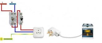
Connection to AC mains
Connecting LEDs from a power supply is not always advisable. Especially when it comes to the need to backlight a switch or indicate the presence of voltage in the power strip. For such purposes, it will be enough to assemble one of the simple circuits for connecting an LED to a 220 V network. For example, a circuit with a current-limiting resistor and a rectifying diode that protects the LED from reverse voltage.
The resistance and power of the resistor are calculated using a simplified formula, neglecting the voltage drop across the LED and diode, since it is 2 orders of magnitude less than the mains voltage:
Due to the high power dissipation (2–5 W), the resistor is often replaced with a non-polar capacitor. Working on alternating current, it seems to “extinguish” excess voltage and hardly heats up.
12V LED systems
LED devices rated at 12 V typically belong to the automotive light class. The automotive network has stabilizers, so there is no need for voltage equalization. LED lighting in cars has become popular - many companies widely use LED lighting in models to illuminate the road and alarm systems, illuminate the interior, trunk and dashboard. However, the use of LEDs in cars has led to an increase in the price of lighting elements, especially headlights and signal light blocks. In some premium models, the cost of the headlight unit is comparable to the price of an inexpensive car.
Also, 12-volt LED diodes are used in construction and decoration of residential premises. Often these are LED strips that not only illuminate the room, but also create light installations. This requires the installation of step-down transformers or drivers connected to the house electrical networks and ensuring long-term operation of the diodes.
Connecting flashing and multi-color LEDs
Externally, flashing LEDs are no different from conventional analogues and can flash in one, two or three colors according to the algorithm specified by the manufacturer. The internal difference is the presence of another substrate under the housing, on which the integrated pulse generator is located. The rated operating current, as a rule, does not exceed 20 mA, and the voltage drop can vary from 3 to 14 V. Therefore, before connecting a flashing LED, you need to familiarize yourself with its characteristics. If they are not there, then you can find out the parameters experimentally by connecting to an adjustable power supply at 5–15 V through a resistor with a resistance of 51–100 Ohms.
The multicolor RGB LED housing contains 3 independent crystals of green, red and blue. Therefore, when calculating resistor values, you need to remember that each glow color has its own voltage drop.
By appearance
Sometimes you can tell the polarity by appearance. Some types of LEDs have a key on the housing - a protrusion or mark. To determine which pin is marked with a key, it is better to consult the reference materials.
The key is at the cathode of the AL102 light-emitting diode.
Appearance of the pin layout of the AL307 LED.
For packageless LEDs produced in the USSR, you can find out the pinout by looking closely at the internal structure of the device through the layer of compound. The cathode terminal has a large area and is made in the form of a flag . This principle could become a standard, but now manufacturers do not strictly adhere to it, so this method is unreliable, especially for elements from an unknown manufacturer. Therefore, this definition of conclusions can be used only for preliminary guidance.
The pinout of domestic LEDs can be recognized by the length of the legs - the anode lead is made shorter. But this is true only for elements that have not been used - when being installed in place, the leads can be cut off arbitrarily.
For clarity, we recommend watching the video.
Once again about three important points
- Direct rated current is the main parameter of any LED. By lowering it, we lose brightness, and by overestimating it, we sharply reduce the service life. Therefore, the best power source is an LED driver; when connected to it, a constant current of the required value will always flow through the LED.
- The voltage given in the datasheet for the LED is not decisive and only indicates how many volts will drop across the pn junction when the rated current flows. Its value must be known in order to correctly calculate the resistor resistance if the LED will be powered by a conventional power supply.
- To connect high-power LEDs, it is important not only to have a reliable power supply, but also to have a high-quality cooling system. Installing LEDs with a power consumption of more than 0.5 W on the radiator will guarantee their stable and long-term operation.
Parallel connection of LEDs is not correct
Parallel connection of LEDs is used when the voltage of the power supply (source) is not enough in order to power a number of serial LEDs. If “specifically theoretically”, then LEDs can be connected in parallel and “stupidly” - connect all the anodes and cathodes of the LEDs. Then connect them to the battery and voila... The LEDs light up! Moreover, only once and for a short time when connected. Next - the end of them.
This circuit for connecting parallel light-emitting diodes is not workable, since the diode resistance is small and easily provokes a short circuit (short circuit).
I’ll immediately dismiss some of the spiteful critics. There are, of course, exceptions... Chinese manufacturers of cheap products are guilty of them. But this is an exception to the rule. If anyone has disassembled Chinese toys or lighters, they have probably seen just such a connection diagram. Where the diodes are connected in parallel, without any extraneous electronic components in their circuit. Why? Yes, everything is simple - in such circuits the current is limited by the internal resistance of the AG1 batteries (tablet). The power in such tablets is minimal and cannot harm the diode. Those. We again come to the conclusion that for normal operation, diodes need a resistor.
I repeat once again - parallel connection of LEDs is used only when the power source is low voltage.
Despite the fact that this type of connection is not very welcome, it is often used. There is one rule in these types of connections - parallel connection of LEDs is never done using ONLY ONE resistor!!!
Well, or for those who only understand visual pictures, an incorrect parallel connection will look like this:
Unfortunately, despite that. that this connection is not correct, again, the ubiquitous Chinese also use it to the fullest... Especially in flashlights. To do this, they overestimate the value of the resistor, so that there is no overload and the product can easily work for a year... Or maybe it won’t work... It depends on your luck.