What is grounding
Grounding involves connecting all electrical appliances to the ground using a special circuit. For this purpose, a separate core is installed in the house, which is directed from the sockets into a metal rod located in the ground at a certain depth.
Why are grounding systems needed:
- Protecting residents from electric shock.
- Protection of electrical devices during sudden voltage changes in the network. Both points imply protective grounding.
- There is also the concept of working grounding, when the windings of generators and power transformers are specially connected to the ground. This procedure is aimed at protecting electrical appliances such as generators.
- In practice, lightning receivers and arresters are often connected to a rod in the ground.
They also lay a protective circuit in case the residual current device (RCD) does not work or is faulty.
Why is grounding needed?
Let’s not scrupulously calculate how much current can kill, it’s still quite unpleasant. I have experienced this myself, I won’t lie at all, more than a dozen times. Reasons: due to childhood - ignorance, and then - the usual Russian randomness and indifference.
The outcome of a situation where a person touches a bare live conductor can be different. If you imagine that a person is hanging in the air, touching nothing else, then nothing happens. He remains safe and healthy, he won’t even understand that the wire is live. Because the rule applies: if there is no circuit, then there is no current. For example, a crow is sitting on a wire - and it’s okay, it’s alive and well, and it’s also cawing from above.
The situation is completely different when a person stands with bare feet on the wet ground and grabs a wire. A closed circuit is created: power transformer - wire - man - earth - and again a transformer. The transformer windings are also grounded in a certain way, and the earth is an excellent conductor.
And bare feet and wet ground are not even necessary. And damp shoes are also a conductor, and the floor is concrete, and tiles, and even waterproofing does not provide guarantees. And electrons ran along this closed circuit, and the unfortunate man’s eyes rolled back and foam came out of his mouth in clumps. It’s good if he unhooks himself from the wire in convulsions, but more often than not, it’s quite the opposite: he squeezes it even more with his crooked fingers. A nightmare picture.
And the crows will also be in trouble if too many of them gather on the wires, and even start flapping their wings. More than once I observed how feathers fly from such a crow coven, because they close two wires, thereby again creating a closed circuit for the flow of current.
By the way, the safety rules for electricians require not only dielectric gloves and insulated tools, but also dielectric mats and boots. These mats and these shoes are additional protection that prevents the creation of a closed circuit if you accidentally touch the conductor with your bare hand. In short, no closed circuit - no current.
Operating principle of ground electrodes
Actually, the ground electrode is a set of conductors that are interconnected and located in the ground at different depths.
Depending on the point of placement of the rods, a distinction is made between loop and remote grounding.
- For the second option, the set of grounding conductors is completely removed outside the house or apartment.
- The first option is characterized by the location of grounding loops around the perimeter of the residential area.
The positive effect in this case is achieved by the uniform distribution of electrical potential over a certain area.
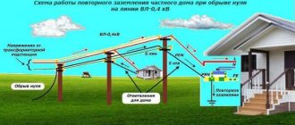
How does grounding work in a private house (TT system)
Now let's move on directly to considering the topic of grounding using the example of a private house with electrical equipment grounded using the TT system. From the distribution transformer along the poles, single-phase 220 Volt power comes to each house - phase and neutral (working neutral wire). In addition to the fact that the neutral has zero potential, at the distribution substation it is connected through a ground loop to the ground loop of our house. Let's explain this in simple words. We know that the earth is a conductor, but not an ideal one. Depending on the soil, resistivity may differ:
| Soil resistivity | |
| Type of soil | Specific resistance, Ohm/m |
| Clay | 50 |
| Limestone is dense | 1000 — 5000 |
| Limestone loose | 500 — 1000 |
| Limestone soft | 100 — 300 |
| Granite and sandstone depending on weathering | 1500 — 10000 |
| Weathered granite and sandstone | 100 — 600 |
| Humus layer | 10 — 150 |
| Silty soils | 20 — 100 |
| Marls of the Jurassic period | 30 — 40 |
| Marls and dense clay | 100 — 200 |
| Mica shales | 800 |
| Clay sand | 50 — 500 |
| Siliceous sand | 200 — 3000 |
| Layered shale soils | 50 — 300 |
| Bare rocky ground | 1500 — 3000 |
| Rocky ground covered with grass | 300 — 500 |
| Wetlands | From a few units to 30 |
| Wet peaty soils | 5-100 |
Let's imagine that somewhere deep down, in some layer, there is a conventional conductor with a resistance close to zero. By making a grounding loop at the substation, we reduce the resistance from the transformer zero to this conductor.
Similarly, with the help of a ground loop in the house (TT grounding system), we reduce the resistance through the ground to this conditional conductive layer. And when a phase breaks down on our grounding, a closed circuit is formed. Why is this necessary? For protection against electric shock, for example, in the event of a phase breakdown on the body of a grounded household appliance. And for clarity and understanding, we will simulate several situations using the Electronics Workbench program.
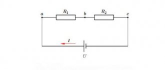
Compare the diagram below with the previous illustration:
| From left to right. 2 Ohm - neutral grounding. Above is the transformer. From it, the phase enters the house (we do not need a neutral wire, since we are simulating a phase breakdown to the housing). In this example, the house ground loop is poor and has a resistance of 100 ohms. A person touches the housing with dangerous potential. Let's take the total resistance of a person, shoes, and floor to be 4000 Ohms. As a result, a current of 2.2 A will appear in the phase-grounding-neutral circuit (this is not enough to trip the circuit breaker), and a dangerous current of 54 mA will flow through the person. |
Consider the second situation, when the loop resistance is 4 ohms:
| Additionally, the voltages between phase and ground through the ground loop are indicated. There was a drop from 220 Volts to 146 Volts. The next fall in the area is from the ground through the transformer ground electrode to the neutral. In this section the voltage is already 73 Volts. That is, the current through grounding does not simply flow into the ground. It moves from a point of higher potential to a point of lower potential through the ground. And during the movement, when a phase breaks down to the ground, voltage is lost due to the resistance of the ground. |
Let's return to the protective functions of grounding. As you can see, with a circuit resistance of 4 ohms, the short circuit current is 36.7 A. And this is enough to trip a properly selected circuit breaker. At the same time, the current passing through the person decreased to 36.8 mA. But this is still a dangerous value if the machine does not operate. And if we are talking about the TT grounding system, then the circuit breakers here must necessarily be supplemented with an RCD (residual current device).
Grounding calculation method
The dimensions, location, and layout of each building are universal, and therefore the grounding will be different. In the process of calculations, it is also important to take into account what type of ground electrode installation is used:
- Vertical type. The metal rod can be located in the surface layers of the earth or at a depth (usually 0.7 meters).
- Horizontal type. The metal pin can be laid on the surface of the ground or in a previously prepared trench (up to 50 cm deep).
To calculate the length of the rod, it is recommended to use a formula that determines the dependence of the length of the metal rod on the distance between adjacent structures.
The standard calculation formula necessarily takes into account the soil resistivity and the diameter of the electrode used.
To determine the total grounding conductor, it is necessary to calculate the total number of rods, and then use the standard table, where the coefficient for the formula has already been calculated.
Rules and requirements of the PUE
At any residential property located within the city limits and beyond, in accordance with the requirements of the PUE, special protection against dangerous voltages of 220/380 Volts is organized. For this purpose, special steel structures called grounding devices (GD) are installed on their territory. Their main purpose is to create conditions that guarantee the protection of people living in the house from electric shock.
In accordance with the PUE, chapter 1.7., part 1, clause 1.7.72, the dimensions of metal blanks are selected taking into account the need to obtain the required resistance to the flow of current into the ground. For various structural elements, these indicators may vary from sample to sample. However, their minimum sizes must comply with the following standards:
- the connecting strip between the pins cannot have a standard size of less than 12x4 mm (section 48 mm2);
- the pins themselves based on the corners are selected with sides of 4x4 mm;
- when using a round reinforcing bar, the cross-section should not be less than 10 mm2;
- the metal pipe should have a wall thickness of about 3.5 mm.
Please note: Having the owner of the house with data on the operating characteristics of the electrical circuit, in particular, will protect animals and residents from electric shock.
When arranging it, it is necessary to act in accordance with the provisions of industry standards regarding the operation of the equipment available at the site.
Known grounding systems
Before characterizing each of the known ground loop circuits and systems, you should familiarize yourself with the basic designations:
- The T symbol indicates the grounding settings on the power supply. In this case we are talking about the ground, because the rods are located in the ground.
- The second letter marking N or T determines the grounding characteristics of household appliance housings.
- There are designations such as C and S, which indicate the subtype of system used.
Among the well-known loop grounding systems, the following should be highlighted:
- TN-C is a system characterized by the combination of neutral and protective conductors. The line consists of a two-core or four-core cable. This scheme is considered very ineffective and is therefore rarely used.
- TN-S. This circuit diagram is characterized by the separation of the neutral and protective conductors. The supply line includes either three-core or five-core cables.
- There is another type of grounding loop, TN-CS, in which both the protective and neutral conductors perform their functions together only in a certain area.
The site, as a rule, starts from a source of electrical energy and ends at the border of a residential building.
The TT system does not come into contact with the source of electrical energy at all, and the grounding ends dead within the house.
Why is re-grounding necessary?
When using grounding made according to the diagrams, one should not exclude the possibility of voltage occurrence that is dangerous to the health and life of people. It occurs as a result of a break in grounded wires and cables located in electrical appliances. In such cases, additional safety is provided by re-grounding, established by a dispatch signal.
Its main function is to reduce the voltage that appears when touching conductive parts of devices. As a result, in the presence of a short circuit, the likelihood of electrical injury in the grounded area is reduced.
Re-grounding works as follows. When a short circuit occurs on the body of a separate device, part of the electric current will go into the ground. There is a decrease in the potential difference between the ground and the body, and the person is protected from electric shock. When using TN-C grounding, the re-grounding device affects the neutral wire. In this case, the conductor is connected to the ground at specified intervals and is used in conjunction with the main ground loop.
If a TN-CS system is used, then re-grounding affects the PEN conductor at the point of its entry into the building. In this option, the protective functions will be carried out using a grounded PE conductor. Exactly the same actions are performed at inputs in electrical installations, the voltage of which does not exceed 1 kV, thereby increasing safety for operating personnel.
Repeated grounding installed at the entrance of a house or bathhouse, regardless of the design, does not allow induced currents to pass into the home network, including microwaves, which can get here through external communications. This provides additional protection for electronic household appliances and equipment. This measure helps reduce the potential on the device body in the event of a break in the neutral conductor.
Re-grounding devices will give maximum effect and increase the level of safety if they are installed in electrical installation circuits together with circuit breakers and fuses. The technical characteristics of these devices must correspond to the parameters of this network. A lot depends on the material and cross-section of the neutral and grounding conductors. The neutral wire is located continuously along the entire length from each device to the neutral of the individual power source. Connections in the area are made by welding, and in the neutral using bolts or welding.
What does the circuit consist of?
To independently organize grounding in a house or country house, you need to know the structure of the main grounding elements:
- Metal rods that are placed in the ground.
- Horizontal metal strips (if the appropriate type of protection against electric current is selected).
- A conductor, which is represented by a strip connecting the ground loop and the electrical panel in the house.
Metal rods made of black steel, galvanized steel, and copper are most often used as rods. In practice, for the installation of a protective circuit, the diameter of the rod used, its cross-section and wall thickness are important.
When carrying out independent work, it is important to remember that the rods cannot be coated with paint or other decorative compounds, since maximum contact of the metal with the ground is necessary.
Modular systems
Of course, if you make a grounding loop with your own hands, you will need to carry out welding work, calculate the network parameters and dimensions of the loop yourself, and ensure the reliability of the connection of the parts of the circuit. In order to save those who do not like it from unnecessary hassle, or simply to facilitate the installation process, you can find modular grounding systems with all the necessary components on sale.
The system is equipped with a set of copper-plated steel rods. Their diameter is 14 mm, and their length is up to 150 cm, and at the ends there is a special thread, also coated with copper. A special brass coupling is screwed onto it, allowing the two rods to be connected to each other. A cone-shaped coupling-tip is screwed onto the lower end of the outer rod to facilitate driving. It is noteworthy that several types of these tips are available for different soils. In addition to the listed components, the set includes special clamps for metal strips and rods. Anti-corrosion protection of structural parts is provided with the help of a special paste, which must be used to cover all components and elements.
Modular grounding systems have a number of characteristic advantages:
- serial connection of many rods allows you to place electrodes at a depth of up to 50 meters;
- thanks to the use of copper-plated stainless steel as a material, the rods are resistant to corrosion and have an increased service life;
- the grounding circuit using a modular system, if necessary, can be placed within one square meter, which is very convenient, for example, in the country;
- installation does not require the use of professional equipment.
In order to organize electrical safety at the dacha and ground it in a private or country house, you can use a ready-made system or make a circuit yourself. When installed correctly, both of these circuits will operate efficiently and safely. Therefore, the choice should be made based on financial or personal preferences and the characteristics of the landscape and layout. The main thing is to carry out correct grounding calculations.
Do-it-yourself grounding of devices
In order to ensure the safety of the residents of the house, you should approach the organization of the grounding loop competently and in detail.
It is important to take into account all the nuances and make all the appropriate calculations (taking into account the qualitative composition of the soil, its resistance, and the area of the residential building).
Instructions on how to make grounding at home with your own hands:
- First of all, you need to choose the right location for the circuit. The site is selected close to the main building, for example, at a distance of up to 200 cm. This approach will allow you to save on materials for the conductor.
- The trench for installation is dug in the shape of a triangle or a straight line, depending on the chosen configuration (can be seen in the grounding photo).
- The selected rods are driven into the ground to the calculated depth.
- The grounding conductors should be welded with a strip of metal, and a second such strip should be brought to the entrance to the residential building to connect to the circuit.
- All welding seams must be treated with an anti-corrosion compound or moisture-proof resin.
- The strip from the contour is brought to the base of the house, and a bolt is attached to the metal strip.
The final step is to attach the bolt with the conductor. The conductor itself should be placed in a shield and connected to the main grounding bus.
Design features of the ground loop
In single-phase and three-phase electrical networks, the ground loop circuits are practically the same. Several electrodes are buried in the ground, after which the entire structure is connected to each other, which becomes a grounding loop. The assembly itself is performed in the form of a triangle or square.
Sometimes the electrodes can be placed in series, forming an open circuit configuration. Each option is selected depending on specific conditions. Connections are made by welding or bolting, and then the finished system is connected to the distribution board through a special cable.
Why is arbitrary location of the contour not allowed? Correct installation requires compliance with certain rules and technical standards. For example, the minimum distance from the building is 1-2 meters, and the maximum is no more than 10 meters.
The depth at which the electrodes should be placed should also be taken into account. First of all, the characteristics of the soil, the presence or absence of groundwater, and their distance from the contour are taken into account. The elements are laid below the freezing level of the ground. This design allows you to create effective grounding of the bathtub in the apartment.
The material for electrodes is most often rods made of ferrous metal. First of all, these are various types of rolled metal - angles, pipes, smooth fittings, I-beams, etc. The complex configuration of the rental does not affect the functionality of the entire scheme; the choice should be made based on the convenience of driving certain structures into the ground. The most commonly used are steel angles.
It should be taken into account that the cross-sectional area of any rolled product must be at least 1.5 cm2. The general layout and number of rods are established experimentally or calculated using a special technique.
Photo of grounding for a private house
What household appliances need to be grounded?
The metal casing of any ungrounded electrical appliance is potentially dangerous. Therefore, it is necessary to ground all electrical appliances in the house with a conductive housing that have protection class I. These include personal computers, boilers, refrigerators, dishwashers and washing machines and other powerful household appliances.
Particular attention should be paid to grounding loads such as boilers, washing machines and dishwashers that have direct contact with water. Water is a dielectric, but due to impurities it still conducts electricity well.
For example, if there is a water leak in a boiler (without a built-in RCD), voltage may appear on its body, and if it comes into contact with it, the user will receive an electric shock. When a washing machine is running in a damp room, the body may also be energized, even if the device is in full working order, provided that the water still “reaches” the voltage source - sockets or non-insulated terminal contacts inside the device.
The hob will also be more likely to leak current. Problems with this device may arise if its body is metal, the phase wire is broken and touches the body, and there is no grounding.
When installing plumbing or underfloor heating in a house due to faulty cable insulation, users are likely to receive an electric shock in places where water is spilled. It will be very risky to be in rooms with high humidity without grounding electrical appliances, for example, in baths and saunas.
Note!
Household appliances whose housing is made of non-conductive materials (protection class II), for example, vacuum cleaners, hair dryers and power tools, do not need to be grounded and can be connected to any outlet.
Therefore, the grounding system for household appliances must be included in the electrical wiring of any private house or apartment.
Operating principle of grounding systems
The main function of any grounding system is to connect electrically conductive parts of instruments and equipment with a special metal structure that is in close contact with the ground. In electrical engineering, this design is known as a ground electrode, grounding device or ground loop. It consists of metal parts made from angles, pipes, and other profile materials, connected to each other by welding.
Protective grounding devices reduce the potential at the point of human contact with the device body and bring it to a safe level. This is the principle of operation of these systems, based on the movement of electric current in the direction of minimum resistance. The whole process takes a very short time, during which an automatic protective device - an RCD - is triggered, completely cutting off the voltage supply.
Modern standards provide for the use of a three-wire wire in the internal electrical network. Among the three cores there is a conductor, with the help of which the socket in a private house is grounded and the subsequent connection of instruments and devices with a pinch circuit located in the ground. When used together with lightning rods, protective systems are additionally equipped with arresters capable of withstanding high currents and voltages.
How to install a ground loop yourself?
When installing grounding with your own hands, installing a circuit, you need to develop a diagram, sketch, drawing. Next, choose a location and mark the area. You will need a tape measure of sufficient length. Next, excavation work is carried out and the structure is assembled. After that, it is buried, mounted, and then connected to the panel. Then the internal circuit (house wiring) is connected and tested using special electrical measuring instruments. The system does not require additional maintenance. It will last for decades if done correctly.
Choosing a place
It is better to place the shield in a special room. Usually this is a pantry, boiler room or closet
It is important to prevent free access for children. The output circuit is placed at least a meter away from the perimeter of the building
The maximum distance is 10 m. It is good when this is a place where people are not unless absolutely necessary. At the moment when the device extinguishes the current leakage, it is better if no one is there. Usually this is behind the house, in fenced garden beds, under decorative artificial plantings, an alpine hill, etc.
Excavation
First you need to mark the area if a linear grounding scheme is used. Pegs are placed in the places where the electrodes will be driven in. Now connect them with straight lines, pull a string, which will serve as a guide for digging a trench. Its depth is from 30 to 50 centimeters. The width is approximately the same. There is no need to remove soil. It will be required at the final stage of installation work before connecting the internal circuit. No waterproofing or backfilling is required.
Assembling the structure
When the excavation work is completed, all that remains is to properly mount the circuit. Pull out the pegs and drive in the pins so that their ends protrude by 15-20 cm. The metal ties are cut to size. It makes sense to re-measure the distance between the pins. A control measurement will eliminate the error factor. The connections are welded using gas or electric welding. Now you can dig a trench, but only except for the entry point into the house, since it also needs to be made, attached, and connected to the switchboard.
Entering the house
The tires are made from materials whose properties were described earlier. The main thing is to securely fasten it to the circuit. Now bring the other end through the wall to the control room. Make a hole in advance in the manner of a terminal so that you can use a bolted connection. When this work is completed, bury the last section of the trench and connect the splitter bar or appropriate conductor to the entry. At this stage, everything depends on the selected type of grounding system for a private house.
Check and control
After connecting the grounding to the panel, you need to make sure that everything is done correctly. Control consists of checking the integrity of the circuits and conductivity. By the way, if you want the circuit to work for sure, do not rush to dig a trench at the previous stages. If a gap is detected, you will have to re-expose the metal structure and repair the fault. Or check the integrity in advance. But even after this, when the entire circuit is connected, it is necessary to double-check its functionality.
Take a lamp with a power of 100-150 W. They screw it into a socket from which small wires extend. This will be the so-called “control”. One wire is connected to the phase, the other to ground. If the installation is done correctly, the light will be bright. Flickering, faint glow, interruption or lack of current indicates a problem. If the light shines dimly, check the reliability of the connections, clean the contacts, tighten the bolts. Follow safety precautions. Do not carry out repair work without disconnecting the building from power.