Often in electronic circuits there is a need to generate different types of signals having different frequencies and shapes, such as square waves, square waves, triangular signals, sawtooth signals and various pulses.
These signals of various shapes can be used as synchronization signals, timing signals, or as trigger pulses. The first step is to understand the basic characteristics that describe electrical signals.
In technical terms, electrical signals are a visual representation of changes in voltage or current over time. That is, in fact, this is a graph of changes in voltage and current, where we plot time on the horizontal axis, and on the vertical axis we plot the voltage or current values at this point in time. There are many different types of electrical signals, but in general, they can all be divided into two main groups.
- Unipolar signals are electrical signals that are always positive or always negative and do not cross the horizontal axis. Unidirectional signals include square waves, clock pulses, and trigger pulses.
- Bipolar Signals - These electrical signals are also called alternating signals because they alternate between positive and negative values, constantly crossing zero. Bipolar signals have a periodic change in the sign of their amplitude. The most common bidirectional signal is the sine wave.
Whether unidirectional, bidirectional, symmetrical, asymmetrical, simple or complex, all electrical signals have three common characteristics:
- The period is the length of time after which the signal begins to repeat. This time value is also called the period time for sinusoids or the pulse width for square waves and is denoted by the letter T.
- Frequency is the number of times a signal repeats itself over a period of time equal to 1 second. Frequency is the reciprocal of the time period, ( *** QuickLaTeX cannot compile formula: f = 1/T *** Error message: Cannot connect to QuickLaTeX server: SSL certificate problem: certificate has expired Please make sure your server/PHP settings allow HTTP requests to external resources (“allow_url_fopen”, etc.) These links might help in finding a solution: https://wordpress.org/extend/plugins/core-control/ https://wordpress.org/support/topic/an -unexpected-http-error-occurred-during-the-api-request-on-wordpress-3?replies=37 ). The unit of frequency is Hertz (Hz). The frequency is 1 Hz and the signal repeats once every 1 second.
- Amplitude is the amount of change in the signal. It is measured in Volts (V) or Amperes (A), depending on which time dependence (voltage or current) we use.
Periodic signals
Periodic signals are the most common because they include sine waves. The alternating current in the outlet at home is a sinusoid, changing smoothly over time with a frequency of 50 Hz.
The time that passes between individual repetitions of a sinusoid cycle is called its period. In other words, this is the time it takes for the signal to start repeating.
The period can vary from fractions of a second to thousands of seconds, as it is related to its frequency. For example, a sine wave that takes 1 second to complete a cycle has a period of one second. Likewise, a sine wave that takes 5 seconds to complete a cycle has a period of 5 seconds, and so on.
So, the length of time it takes for a signal to complete a full cycle of its change before it repeats again is called the period of the signal and is measured in seconds. We can express the signal as the number of cycles T per second as shown in the figure below.
Links
- [standartgost.ru/%D0%93%D0%9E%D0%A1%D0%A2%2016465-70 GOST 16465-70].
| This is a preliminary article about electronics. You can help the project by adding to it. |
| : Incorrect or missing image | To improve this article it is desirable:
|
Sine wave
Period time is often measured in seconds (s), milliseconds (ms), and microseconds (µs).
For a sine waveform, the time period of the signal can also be expressed in degrees, or in radians, given that one complete cycle is equal to 360° (T = 360°), or, if in radians, then
*** QuickLaTeX cannot compile formula: 2 \pi *** Error message: Cannot connect to QuickLaTeX server: SSL certificate problem: certificate has expired Please make sure your server/PHP settings allow HTTP requests to external resources (“allow_url_fopen”, etc .) These links might help in finding a solution: https://wordpress.org/extend/plugins/core-control/ https://wordpress.org/support/topic/an-unexpected-http-error-occurred-during- the-api-request-on-wordpress-3?replies=37 (T = *** QuickLaTeX cannot compile formula: 2 \pi *** Error message: Cannot connect to QuickLaTeX server: SSL certificate problem: certificate has expired Please make make sure your server/PHP settings allow HTTP requests to external resources (“allow_url_fopen”, etc.) These links might help in finding a solution: https://wordpress.org/extend/plugins/core-control/ https://wordpress. org/support/topic/an-unexpected-http-error-occurred-during-the-api-request-on-wordpress-3?replies=37
).
Period and frequency are mathematically the reciprocals of each other. As the signal period time decreases, its frequency increases and vice versa.
The relationship between the signal period and its frequency:
*** QuickLaTeX cannot compile formula: f = \frac{1}{T} *** Error message: Cannot connect to QuickLaTeX server: SSL certificate problem: certificate has expired Please make sure your server/PHP settings allow HTTP requests to external resources (“allow_url_fopen”, etc.) These links might help in finding a solution: https://wordpress.org/extend/plugins/core-control/ https://wordpress.org/support/topic/an-unexpected-http -error-occurred-during-the-api-request-on-wordpress-3?replies=37
Hz
*** QuickLaTeX cannot compile formula: T = \frac{1}{f} *** Error message: Cannot connect to QuickLaTeX server: SSL certificate problem: certificate has expired Please make sure your server/PHP settings allow HTTP requests to external resources (“allow_url_fopen”, etc.) These links might help in finding a solution: https://wordpress.org/extend/plugins/core-control/ https://wordpress.org/support/topic/an-unexpected-http -error-occurred-during-the-api-request-on-wordpress-3?replies=37
c
One hertz is exactly equal to one cycle per second, but one hertz is a very small value, so you often see prefixes indicating the order of magnitude of the signal, such as kHz, MHz, GHz and even THz
| Prefix | Definition | Record | Period |
| Kilo | thousand | kHz | 1 ms |
| Mega | million | MHz | 1 µs |
| Giga | billion | GHz | 1 ns |
| Tera | trillion | THz | 1 ps |
PWM signal
Hardware
To generate a PWM signal with a given filling, there is a standard function analogWrite(pin, duty), discussed in more detail in the lesson about the PWM signal, and the frequency can be changed by reconfiguring the timer, as in the lesson about increasing the PWM frequency. In fact, timers allow you to configure the PWM signal with a more precise or higher frequency and different fill ranges (up to 10 bits), but this is not provided in the Arduino core. If you need this, you can use the GyverPWM library. Example:
pinMode(10, OUTPUT); // run PWM on D10 with a frequency of 150'000 Hz, FAST_PWM mode PWM_frequency(10, 150000, FAST_PWM);
Software PWM
Software generation of a PWM signal can be useful if there is not enough extra timer or the PWM frequency is low and will not affect the rest of the code, but it will not affect it. The PWM signal on the “millis” can be organized in this way, switching the output over two periods:
Soft PWM on millis()
The PWMgen(fill) function in this implementation should be called as often as possible in the main program loop:
#define PWM_PRD 20 // PWM period, ms #define PWM_PIN 13 // PWM pin void setup() { pinMode(PWM_PIN, OUTPUT); } void loop() { PWMgen(analogRead(0) / 4); // take the PWM value from A0, 0.. 255 } void PWMgen(byte duty) { static uint32_t tmr; static bool flag; if (duty == 0) digitalWrite(PWM_PIN, LOW); else if (duty == 255) digitalWrite(PWM_PIN, HIGH); else { int prd = (PWM_PRD * duty) >> 8; // equivalent / 255 if (millis() - tmr >= (flag ? prd : PWM_PRD - prd)) { tmr = millis(); digitalWrite(PWM_PIN, flag = !flag); } } }
Here, on each call, we calculate a new switching period, spending some time on this. You can count the period in a separate function, and generate the PWM itself separately. The implementation can be viewed in the PWMrelay library.
Semi-hardware PWM
You can reduce the load on the processor by assigning time to a hardware timer. Examples based on GyverTimers (for ATmega328, 2560):
8 bit PWM
// PWM frequency = ~ (call frequency tick / 256); #define PWM_FREQ 100 // PWM frequency #define PWM_PIN 13 // PWM pin #include // connect the volatile hardware timer library uint8_t pwm_duty = 0; // variable for storing PWM filling 0-255 volatile uint8_t counter = 0; // analogue of the timer counting register void setup() { Timer2.setFrequency(256L * PWM_FREQ); // interrupt frequency Timer2.enableISR(); // enable timer interrupts pinMode(PWM_PIN, OUTPUT); // pin as output } void loop() { // set the duty cycle of the PWM potentiometer from pin A0 pwm_duty = analogRead(0) / 4; // 1023 -> 255 // delay setting the value to avoid jumps delay(100); } // timer interrupt ISR(TIMER2_A) { if (!pwm_duty) digitalWrite(PWM_PIN, LOW); // PWM filling == 0 else { if (!counter) digitalWrite(PWM_PIN, HIGH); // when the counter is reset HIGH else if (counter == pwm_duty) digitalWrite(PWM_PIN, LOW); // if there is a match LOW counter++; } }
Setting the bit depth
// PWM frequency = ~ (tick call frequency / (PWM depth + 1)); #define PWM_DEPTH 100 // PWM bit depth #define PWM_PIN 13 // PWM pin #include // connect the volatile hardware timer library uint8_t pwm_duty = 0; // variable for storing PWM filling 0-255 volatile uint8_t counter = 0; // analogue of the timer counting register void setup() { Timer2.setPeriod(10); // timer interrupts with a frequency of 100 kHz Timer2.enableISR(); // enable timer 2 interrupts pinMode(PWM_PIN, OUTPUT); // set the pin to the output } void loop() { // get the PWM filling from potentiometer A0 pwm_duty = map(analogRead(A0), 0, 1023, 0, PWM_DEPTH); // delay setting the value to avoid jumps delay(100); } ISR(TIMER2_A) { if (!pwm_duty) digitalWrite(PWM_PIN, LOW); // PWM filling == 0 else { if (!counter) digitalWrite(PWM_PIN, HIGH); // when the counter is reset HIGH else if (counter == pwm_duty) digitalWrite(PWM_PIN, LOW); // if there is a match LOW if (++counter > PWM_DEPTH) counter = 0; // check for overflow } }
As you know, digitalWrite() is a very heavy and long function, and to generate soft PWM it is recommended to replace it with something faster, for example, direct access to a register or this construction (for ATmega328p):
void digitalWriteFast(uint8_t pin, bool x) { if (pin < { bitWrite(PORTD, pin, x); } else if (pin < 14) { bitWrite(PORTB, (pin - 8), x); } else if ( pin < 20) { bitWrite(PORTC, (pin - 14), x); } }
If the number of standard PWM outputs is not enough, you can raise the semi-hardware PWM on the timer by several pins at once:
Multichannel software PWM
#define PWM_FREQ 100 // PWM frequency const uint8_t pwm_pins[] = {2, 3, 4, 5}; // pins #include // connect the hardware timer library const uint8_t PWM_PINS = sizeof(pwm_pins); volatile uint8_t pwm_duty[PWM_PINS]; // variable for storing PWM filling 0-255 volatile uint8_t counter; // counter void setup() { Timer2.setFrequency(256L * PWM_FREQ); // timer interrupts Timer2.enableISR(); // enable timer 2 interrupts // set pins to the output for (int i = 0; i < PWM_PINS; i++) pinMode(pwm_pins , OUTPUT); // filling pwm_duty[0] = 10; pwm_duty[1] = 20; pwm_duty[2] = 128; pwm_duty[3] = 128; } void loop() { } // timer interrupt ISR(TIMER2_A) { for (int i = 0; i < PWM_PINS; i++) { if (!pwm_duty ) digitalWrite(pwm_pins , LOW); // PWM filling == 0 else { if (!counter) digitalWrite(pwm_pins , HIGH); // when the counter is reset HIGH else if (counter == pwm_duty ) digitalWrite(pwm_pins , LOW); // if there is a match LOW } } counter++; }
This algorithm is not the most optimal; a more interesting one can be found in GyverHacks.
Note : all three algorithms use a match check with counter == pwm_duty. This greatly reduces the use of CPU time in the interrupt, but with a sharp decrease in filling, it can lead to single “flashes” of filling to the maximum, since the condition is not met. For smoother operation, you can make counter >= pwm_duty, then the condition will be “adjusted” to the new filling value each time, but the pin will be set on every tick!
You can introduce PWM fill buffering and take a new value only when the counter is zero, this will solve the problem:
Buffered PWM
// soft PWM with buffering #define PWM_FREQ 100 // PWM frequency #define PWM_PIN 13 // PWM pin #include // connect the volatile hardware timer library uint8_t pwm_duty = 0; // variable for storing PWM filling 0-255 volatile uint8_t counter = 0; // analogue of the volatile timer counting register uint8_t real_duty = 0; void setup() { Timer2.setFrequency(256L * PWM_FREQ); // interrupt frequency Timer2.enableISR(); // enable timer interrupts pinMode(PWM_PIN, OUTPUT); // pin as output } void loop() { // set the duty cycle of the PWM potentiometer from pin A0 pwm_duty = analogRead(0) / 4; // 1023 -> 255 } // timer interrupt ISR(TIMER2_A) { if (!pwm_duty) digitalWrite(PWM_PIN, LOW); // filling PWM == 0 else { if (!counter) { // at counter == 0 digitalWrite(PWM_PIN, HIGH); // HIGH real_duty = pwm_duty; // take from the “buffer” } else if (counter == real_duty) digitalWrite(PWM_PIN, LOW); // if there is a match LOW counter++; } }
You can apply buffering to other algorithms.
Servo Library
As you know, RC servos are controlled using a PWM signal with a frequency of ~50 Hz and a pulse duration of ~500 to ~2500 microseconds. The standard Servo.h library implements the generation of a semi-hardware PWM signal, and the number of pins can be changed during operation. The library can be used as PWM generation if its parameters are suitable for use.
Meander
Square waves are widely used in electronic circuits for timing and synchronization signals because they have a symmetrical square wave shape with equal half-cycle lengths. Almost all digital logic circuits use square wave signals at their inputs and outputs.
Since the shape of the meander is symmetrical, and each half of the cycle is the same, the duration of the positive part of the pulse is equal to the period of time when the pulse is negative (zero). For square waves used as timing signals in digital circuits, the duration of the positive pulse is called the period fill time.
For meander, filling time
*** QuickLaTeX cannot compile formula: \tau *** Error message: Cannot connect to QuickLaTeX server: SSL certificate problem: certificate has expired Please make sure your server/PHP settings allow HTTP requests to external resources (“allow_url_fopen”, etc. ) These links might help in finding a solution: https://wordpress.org/extend/plugins/core-control/ https://wordpress.org/support/topic/an-unexpected-http-error-occurred-during-the -api-request-on-wordpress-3?replies=37
equal to half the signal period. Since the frequency is equal to the reciprocal of the period, (1/T), then the frequency of the meander:
*** QuickLaTeX cannot compile formula: \ *** Error message: Cannot connect to QuickLaTeX server: SSL certificate problem: certificate has expired Please make sure your server/PHP settings allow HTTP requests to external resources (“allow_url_fopen”, etc.) These links might help in finding a solution: https://wordpress.org/extend/plugins/core-control/ https://wordpress.org/support/topic/an-unexpected-http-error-occurred-during-the- api-request-on-wordpress-3?replies=37
For example, for a signal with a fill time of 10 ms, its frequency is:
*** QuickLaTeX cannot compile formula: f = \frac{1}{(10+10) \cdot 10^{-3}c} = 50 *** Error message: Cannot connect to QuickLaTeX server: SSL certificate problem: certificate has expired Please make sure your server/PHP settings allow HTTP requests to external resources (“allow_url_fopen”, etc.) These links might help in finding a solution: https://wordpress.org/extend/plugins/core-control/ https: //wordpress.org/support/topic/an-unexpected-http-error-occurred-during-the-api-request-on-wordpress-3?replies=37
Hz
Square waves are used in digital systems to represent the logical “1” level by large values of its amplitude and the logical “0” level by small amplitude values.
If the filling time is not equal to 50% of the duration of its period, then such a signal already represents a more general case and is called a rectangular signal. If or if the time of the positive part of the signal period is short, then such a signal is an impulse.
Sine or meander?
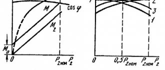
Autonomous and uninterruptible power supply systems, as a rule, are used to ensure the operation of equipment with a power supply of 220 V. In this case, the issue of providing 220 V power supply is acute. As soon as we talk about 220 V power, it is necessary to clearly understand that there are two units of power measurement - watts (W), and volt-amperes (VA). 1 W = 1.4 VA or 1 VA = 0.7 W
As a rule, units and inverters indicate values in volt-amperes. Therefore, to obtain the maximum power value in Watts, this value must be divided by 1.4. In this case, the power of the electricity consumer can be indicated depending on the type of device in any of two units. Let's say a regular incandescent lamp is rated in watts. Those. a 100 W light bulb cannot be connected to a UPS or Inverter with a rating of 100 VA, but only to at least 150 VA.
Inverters and uninterruptible power supplies (UPS)
can be classified according to the form of the output voltage - sine or modified sine (square wave with pauses).
Sine or meander?
Most consumers don’t even think about the shape of the output voltage of this device. But most of the devices on the market do not produce “pure sine”
, and the so-called
“modified sine” (such devices are much cheaper than “sinusoidal”)
.
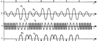
Modified sine is an approximation to a sine wave using square wave signals. The roughest but simplest approximation is a meander - a rectangular signal of alternating polarity (Fig. 1). Moreover, we are talking about the transfer of signal energy, i.e. about the equality of the effective voltage value (the area under the voltage curve). As a result, the amplitudes of the two signals - sine and meander - are different. To get Ueff = 220 V, the square wave must have an amplitude of 220 V, and the sine wave must have an amplitude of 311 V.
In practice, the meander is not used, because at the moment of a sharp change in polarity, very unpleasant effects occur in the equipment. A meander with a pause, or the so-called “modified sine” (Fig. 2), is usually used.
More expensive devices use better approximations to the sine by increasing the number of steps. In Fig. Figure 3 shows the next level of approximation. Increasing the number of steps, we will gradually obtain a signal whose shape differs little from a sine.
Why is sine better than modified sine?
There is equipment for which the signal shape is important. First of all, this is equipment that is sensitive to interference, equipment with transformer power supplies, electric motors, compressors, etc. There are consumers who are insensitive to the signal shape - these are incandescent lamps, simple heating devices, devices with transformerless switching power supplies (computers, modern TVs).
What happens when a modified sine wave is applied to a transformer power supply?
The efficiency of the transformer sharply decreases, as a result of which it begins to overheat and may fail. In addition, a bad (usually Chinese clandestine-made) transformer will begin to produce extraneous sounds during operation. This problem is not relevant when the power of the transformer is obviously significantly higher than required, but such situations occur only in devices with very low consumption (several watts). Starting with devices that consume 10 W, the transformer is usually optimized, and it is not recommended to use a device with a modified sine wave with such consumers. Electric motors have the same effect - reduced efficiency, overheating and extraneous sounds. It is not recommended to use a modified sinus to power sensitive equipment (for example, medical), because the modified sine is a sure source of interference.
How to determine the output waveform?
Of course, after reading the passport. If the output shape is sinusoidal, then the manufacturer will definitely write it that way. And phrases like “quasi-sine” or “modified sine” indicate a non-sinusoidal shape of the output signal. Sometimes the harmonic coefficient is indicated in the passport. If it is less than 8%, then it is an almost perfect sine. It is worth noting that with the same output power, the price of a converter with a sine output will be at least 2 times higher!
There are no problems with purchasing a regular computer UPS (uninterruptible power supply) - this is easier to do at any computer company. With a good powerful inverter the situation is much more complicated. Buying a high-quality device will be quite difficult - very few companies in Russia deal with such equipment (one of the best is Free Energy). The production and supply of 220 V powerful inverters designed to provide power to communication systems is well established, but meeting the very high technical requirements of the Ministry of Communications leads to the fact that such equipment is quite expensive.
| pure sine | Quasi-sine |
Author
: Yanovsky M.G.
Square wave
Rectangular signals differ from meanders in that the durations of the positive and negative parts of the period are not equal. Square wave signals are therefore classified as single-ended signals.
In this case, I have depicted a signal that takes only positive values, although, in general, negative signal values can be significantly below the zero mark.
In the example shown, the duration of the positive pulse is longer than the duration of the negative one, although this is not necessary. The main thing is that the signal shape is rectangular.
Signal repetition period ratio
*** QuickLaTeX cannot compile formula: T *** Error message: Cannot connect to QuickLaTeX server: SSL certificate problem: certificate has expired Please make sure your server/PHP settings allow HTTP requests to external resources (“allow_url_fopen”, etc.) These links might help in finding a solution: https://wordpress.org/extend/plugins/core-control/ https://wordpress.org/support/topic/an-unexpected-http-error-occurred-during-the- api-request-on-wordpress-3?replies=37 , to the duration of the positive pulse *** QuickLaTeX cannot compile formula: \tau *** Error message: Cannot connect to QuickLaTeX server: SSL certificate problem: certificate has expired Please make sure your server/PHP settings allow HTTP requests to external resources (“allow_url_fopen”, etc.) These links might help in finding a solution: https://wordpress.org/extend/plugins/core-control/ https://wordpress.org /support/topic/an-unexpected-http-error-occurred-during-the-api-request-on-wordpress-3?replies=37
, is called duty cycle:
*** QuickLaTeX cannot compile formula: \ *** Error message: Cannot connect to QuickLaTeX server: SSL certificate problem: certificate has expired Please make sure your server/PHP settings allow HTTP requests to external resources (“allow_url_fopen”, etc.) These links might help in finding a solution: https://wordpress.org/extend/plugins/core-control/ https://wordpress.org/support/topic/an-unexpected-http-error-occurred-during-the- api-request-on-wordpress-3?replies=37
The reverse duty cycle value is called the duty cycle:
*** QuickLaTeX cannot compile formula: \ *** Error message: Cannot connect to QuickLaTeX server: SSL certificate problem: certificate has expired Please make sure your server/PHP settings allow HTTP requests to external resources (“allow_url_fopen”, etc.) These links might help in finding a solution: https://wordpress.org/extend/plugins/core-control/ https://wordpress.org/support/topic/an-unexpected-http-error-occurred-during-the- api-request-on-wordpress-3?replies=37
Calculation example
Let there be a rectangular signal with a pulse duration of 10 ms and a duty cycle of 25%. It is necessary to find the frequency of this signal.
The duty cycle is 25% or ¼, and coincides with the pulse width, which is 10ms. Thus, the signal period should be equal to: 10ms (25%) + 30ms (75%) = 40ms (100%).
*** QuickLaTeX cannot compile formula: f = \frac{1}{T} = \frac{1}{(10 + 30) \cdot 10^{-3}c} = 25 *** Error message: Cannot connect to QuickLaTeX server: SSL certificate problem: certificate has expired Please make sure your server/PHP settings allow HTTP requests to external resources (“allow_url_fopen”, etc.) These links might help in finding a solution: https://wordpress.org/extend /plugins/core-control/ https://wordpress.org/support/topic/an-unexpected-http-error-occurred-during-the-api-request-on-wordpress-3?replies=37
Hz
Square wave signals can be used to control the amount of power delivered to a load, such as a lamp or motor, by varying the duty cycle of the signal. The higher the duty cycle, the greater the average amount of energy must be supplied to the load, and, accordingly, a lower duty cycle means a lower average amount of energy supplied to the load. A great example of this is the use of pulse width modulation in speed controllers. The term pulse width modulation (PWM) literally means “change in pulse width.”
Add a link to a discussion of the article on the forum
RadioKot >Competitions >Congratulate Kot as a human being 2022! >
| Article tags: | Add a tag |
Universal Signal Generator
Author: Integrator Published September 20, 2017 Created using KotoEd. Participant of the Competition “Congratulate the Cat as a Human 2022!”
One day, taking out of the box a piece of a breadboard with tangled wires and an NE555 soldered to it, I realized that I needed a normal signal generator. I wanted to get both good functionality and simplicity of the circuit using available components. There were several interesting circuit solutions found on the Internet. However, upon closer examination, they all revealed their shortcomings. As a result, it was decided to make our own generator, with the maximum possible number of functions, so that it would be enough, if not for all, then for most of the needs.
It differs from similar devices assembled on the basis of AVR by a wide selection of generated signals, more accessible and cheaper components and single-polar power supply. Of course, it cannot be compared with factory instruments, but it may be useful in a home laboratory.
Characteristics.
Waveform:
- sinus
- triangle
- saw
- reverse saw
- ECG
- noise
- meander
- high frequency
- PWM (rectangle with adjustable duty cycle)
- specially shaped pulses
- TV signal(bands)
Frequency:
- Sine, triangle, saw, reverse saw, ECG: 1Hz - 111.1KHz
- Square wave: 1Hz - 500.0KHz
- Square Wave(High Frequency): 1MHz, 2MHz, 4MHz, 8MHz
PWM:
- 1Hz-99KHz
- fill factor 1% - 99%
- possibility of external synchronization
Special shape pulses:
- Tmin. = Trise+Ton+Tfall+Toff = 8µs
- Tmax = Trise+Ton+Tfall+Toff = 4000000us
- number of pulses 1 - 65535
- possibility of triggering by external impulse
Supply voltage 12V Signal amplitude 0 - 5V Offset -3 - 3V DAC bit size 8bit Sampling frequency 1.78MHz
The generator has 2 outputs - A, D and input - E. Signals in sine, triangle, saw, reverse saw, ECG, noise, TV, pulse modes are output to output A.
Output D is digital; it outputs signals in PWM, square wave, and high frequency modes. There is a protective resistor at the output.
Input E is used to trigger PULSE mode and for synchronization in PWM mode. There is a protective resistor and a zener diode at the input; there is no pull-up to the power supply.
All set parameters are saved in the controller’s non-volatile memory after the generator is started.
Operating modes.
After turning on the device, the display in the top line shows the current operating mode and status (on or off). The bottom line indicates additional parameters. When you press the mode button, the operating mode of the device changes. When you press the set button, the mode for setting parameters for the current mode is activated. The on/off button starts or turns off the generator. Switch F turns the analog filter on output A on and off.
Sine (SINE), triangle (TRIANGLE), saw (SAWTOOH WAVE), reverse saw (RSAWTOOH WAVE), ECG (ECG) . The signal of the selected shape is generated by the tabular method. To switch to the frequency input mode, you need to press the set button. In this mode, the top line shows the current frequency, and the bottom line shows the step of the number being set. The value is set using the +/- buttons, the step can be changed with the mode button. Upon completion of the input, you need to press the set button again, after which the generator will switch to the main mode.
Sine 1KHz, 5V, offset 1V.
Saw 21KHz.
triangle 1KHz.
ECG 1KHz
Noise (NOISE). Generates noise, uses the standard library function rand(), has no configurable parameters.
Meander (SQUAREWAVE). Generates rectangular pulses with a duty cycle of ~50% using the DDS method.
High frequency (HIGH SPEED). Generates high frequency rectangular pulses with a duty cycle of ~50%. It has only 4 frequency values: 1MHz, 2MHz, 4MHz, 8MHz.
PWM (PWM). Generates rectangular pulses with adjustable duty cycle by dividing the clock frequency. In this mode there are 3 adjustable parameters, the transition between them is carried out sequentially by pressing the set button.
F - frequency is set similarly to the previous modes.
DC - duty cycle can be set in the range 1-99% in 1% increments using the +- buttons.
PWM 21KHz, 80%.
EXT SYNC - external synchronization can have 3 values, which are selected with the +- buttons:
- NO – absent, the generator will work all the time after pressing the on button.
- HIGH – the generator will operate when there is a high level at input E.
- LOW - the generator will operate when there is a low level at input E.
PWM 21KHz, 80%, external sync. E=H.
Pulses of a special shape (PULSE). Allows you to generate pulses with a specified period of linear rise/fall of the signal level. Has 6 customizable parameters.
Trise — pulse rise period 2 — 1000000 μs; Ton - high level period 2 - 1000000 µs; Tfall—pulse decay period 2—1000000 μs; Toff - low level period 2 - 1000000 μs, set with the +- buttons, the step is selected with the dir button.
Trise=Ton=Tfall=Toff=100µs, N=ND
N – number of pulses, set using +- buttons, step selected by mode button.
- Range 1 - 65535, after startup the generator will output the set number of pulses to output A.
- ND – not defined, the generator will work all the time after pressing the on button.
Trise= 3μs,Ton=Tfall=Toff=100μs, N=3
TRIGGER - starting the generator with an external pulse at input E. Values selected using the +- buttons:
- NO – absent, the generator will work all the time after pressing the on button.
- RISE – after pressing the on button. the generator will start only on the edge of the pulse at input E. While waiting, W:R will be shown in the top line of the display
- FALL - after pressing the on button. the generator will start only when the pulse at input E falls. While waiting, W:F will be shown in the top line of the display
TV (TV). Generates an analog video signal - vertical stripes. For proper operation, you need to set the offset to 0V, amplitude to 5V. Output A is connected to the video input of the TV.
Reset settings.
It may be necessary if your EEPROM has not been flashed or some kind of collapse occurred during the setup process and now the device shows something terrible. To reset the settings in a de-energized generator, press the set button, then turn on the power and, without releasing the button, wait for 5 seconds. After this, the settings in the EEPROM are overwritten to the default ones.
Scheme.
The entire digital part is implemented in the Atmega8A microcontroller operating at a frequency of 16 MHz. A resistive R2R DAC is connected to the microcontroller, producing an analog signal. From the output of the DAC, the signal goes to the buffer amplifier on U2B. Then it passes through a 2nd order active low-pass filter, assembled according to the Butterworth circuit on U2A, with a cutoff frequency of 300 KHz. The filter was calculated using the online calculator from AD.
Switch SW5 allows you to select whether to record a signal directly from the repeater or passed through a low-pass filter. Next in the circuit is an inverting amplifier with an adjustable gain of 0 - 0.5. This coefficient was not chosen by chance. The fact is that the lower supply voltage of the op-amp TL082 should be 1.5V lower than the output voltage. Those. with an amplitude of 5V, the supply should be -6.5V, which would require a change in the voltage converter circuit. The signal then goes to the second inverting amplifier, which shifts the level relative to the bias voltage, controlled by resistor RV1. It also restores the signal amplitude, which was previously reduced in U3B.
Signals in PWM and square wave (high frequency) modes are generated by a microcontroller timer-counter by dividing the clock frequency. In meander mode - using the DDS software method.
To save I/O ports, the display is connected according to a write-only circuit, with the RW pin grounded. Lines D4 – D7 have a dual purpose; in addition to transmitting data to the display, control buttons are connected to them. To avoid short circuits, when pressing the button and transmitting data at the same time, protective resistors are installed. Data transfer and reading of button states occurs sequentially.
Also on the board there are contact pins for the Rx and Tx lines, to which the software UART 19200 8b1 is output. In the current firmware version, this interface works only for output.
Via the V_GEN line, the controller produces rectangular pulses with a frequency of ~20 KHz, which are supplied to the voltage converter. It generates the -5.6V needed to power the op-amps.
A little theory.
The generator uses the direct digital frequency synthesis (DDS) method. The algorithm from the AVR DDS signal generator V2.0 device was taken as a basis and modified. In particular, by replacing reading table values from flash with a buffer in RAM, it was possible to reduce the work cycle time by 1 clock cycle. Which led to an increase in the sampling frequency from 1.6 to 1.78 MHz. Based on it, an algorithm was written for generating a rectangle and pulses with an arbitrary linear rise and fall time.
The simplest digital-analog generator on an MK is quite easy to make. A table of values of an analog signal (for example, a sinusoid) for 1 period is taken. And it is serially output to the MK port to which the DAC is connected. The frequency of the output signal will be equal to:
FOUT = FCLK/C; FCLK is the frequency at which output to the port occurs (sampling frequency), C is the number of values in the table.
The main disadvantage of this method is its unsatisfactory frequency tuning ability. Since the sampling frequency is divided by an integer, the tuning step will be variable, and the smaller the division factor, the larger the relative step size.
With direct digital synthesis, the sampling rate remains constant. A special variable is introduced into the algorithm, which stores the current value of the signal phase, called the phase accumulator. In the specific example, its size is 24 bits. The main code of the algorithm is written in assembler:
;the address of a buffer in RAM is loaded into register Z, containing a table of 256 values of one period of the generated signal; for the algorithm to work correctly, the buffer address must be aligned at 0x100h, i.e., start at 0xXX00h; in this case, the buffer is located at address 0x0100 ldi zh , 0x01 ldi zl, 0
;registers r18, r19, zl constitute a 24-bit phase accumulator; the highest 8 bits are also an index in the signal table eor r18, r18 ;resetting the accumulator eor r19, r19 ;resetting the accumulator
;in registers r22, r23, r24 there is a 24-bit value of the phase increment - M
1: add r18, r22 ;add accumulator with M adc r19, r23 ;add accumulator with M adc zl, r24 ;add accumulator with M ld r0, z ;load value from table at address Z out _SFR_IO_ADDR(R2RPORT), r0 ;output values in the DAC sbic _SFR_IO_ADDR(BTN_PIN), START ;condition for interrupting the cycle, if the button is pressed we exit rjmp 1b ;jump to the beginning of the cycle
In a cycle that rotates at a predetermined frequency FCLK, a certain constant number is added to the phase accumulator, which is called the phase increment - M. In this case, the value of the accumulator increases at a constant speed, and its highest 8 bits are used as an index in the table of analog signal values. The battery overflow period will be equal to one period of the generated signal. In this case, the period itself may not be a multiple of the clock frequency, see the graph.
FOUT = M * FCLK/N where FOUT is the output frequency, FCLK is the sampling frequency, M is the phase increments, N is the maximum value of the phase accumulator.
the sampling frequency is FCLK = F_CPU/NUM_CYCLES, where F_CPU is the processor clock frequency - 16 MHz, NUM_CYCLES is the number of machine cycles per cycle pass - 9 FCLK = 16000000/9 = 1777777Hz
The minimum signal frequency will be at M = 1 FMIN = 1 * 1777777 / 2^24 = 0.105 Hz, and it is also the frequency change step.
The phase increment value for the required frequency can be calculated as follows:
M = FOUT * N / FCLK
As the frequency increases, the number of samples decreases and the signal shape becomes simpler and steps appear. Therefore, the maximum frequency is limited to 111.1 KHz, at which the signal shape is more or less preserved. Also, to reduce the steps, an analog filter at 300 KHz was added to the circuit.
The algorithm for generating a meander using the DDS method is not fundamentally different. The only difference is that the signal is generated by the nogodryg, and not through the DAC. The level at the MK port pin is simply inverted after the phase accumulator overflows.
ldi zh, 1<;Load the output mask into zh
;resetting the battery ldi zl, 0 eor r18, r18 eor r19, r19 in r0, _SFR_IO_ADDR(HSPORT) ; remember the state of port 1: add r18, r22 ; adding the accumulator with M adc r19, r23 ; adding the accumulator with M adc zl, r24 ; adding the accumulator with M BRCC 2f eor r0, zh ; if the accumulator overflows, invert the bit of port 2: out _SFR_IO_ADDR(HSPORT), r0 ;output sbic _SFR_IO_ADDR(BTN_PIN), START ;condition for interrupting the cycle, if the button is pressed we exit rjmp 1b ;jump to the beginning of the cycle
And the formulas will change a little: FOUT = M * FCLK/(2*N);
M = FOUT * 2 * N / FCLK
This method of generating a rectangular signal has greater frequency setting accuracy than simple division by a timer-counter (which is used in PWM mode). However, the signal constantly contains edge jitter due to phase mismatch with the sampling frequency.
Well, I hope someone understands something from my chaotic explanation.
Firmware.
In addition to the program file, you also need to flash the EEPROM. Fuse bits: LOW = 0xFF, HIGH = 0xD9. Be careful, during subsequent firmware the controller without quartz may not be detected by the flasher!
Assembly, configuration.
For R2R DACs, it is advisable to take resistors from the same batch, or select them using a multimeter, so that their resistance differs by no more than 0.5%. Attached to the article is an updated printed circuit board, it differs from the one in the photo in the case.
The new PCB has areas for SMD resistors so that people don’t have to worry about drilling an additional 48 holes. After turning it on, the first thing you need to do is check the presence of all supply voltages, especially -5.6V, at the op-amp terminals. Next, using the tuning resistor RV3, you need to ensure that the voltage at the extreme terminals of the resistor RV1 is approximately equal to -1V and 1V. This completes the setup.
Frame.
The body of the device is glued together from 4mm plywood. It is better to use sanded plywood for this, as it is smoother and has fewer defects. All body parts are cut out by hand with a jigsaw.
If you have a CNC machine, everything is done much easier, but if anyone decides to do it manually, I want to give some advice.
First, life-size details of the future body are drawn in CAD or manually, on a checkered sheet. You should consider the placement of the display and control knobs, and other parts. The joint tenons at the edges of the parts should not be made too narrow, otherwise you will have a hard time adjusting them when gluing. The optimal width of tenons/grooves for 4mm plywood is 15 - 25mm. After the drawing is transferred to plywood, special attention should be paid to the geometry so that there are no distortions and all angles are right. Then the internal holes are drilled or sawed out, and only then the part itself is cut out.
To avoid chipping and scuffing the veneer when drilling large holes, use only sharp drills. Pre-drill a small diameter hole in the center, and do not press too hard when feeding.
After all the elements of the body have been cut, the most tedious and crucial moment comes, on which the final appearance of the body depends. It is necessary to adjust the tenons/grooves on the parts to be connected. It is better to do this with a narrow flat file. Place the part on a base with a flat edge (a piece of chipboard, for example), so that the grooves are at the same level. As a result, the parts should fit well together with minimal gaps.
EDP (epoxy) glue is best suited for gluing, as it fills gaps and does not shrink after hardening. But I glued it with ordinary stationery PVA-M, the result was not bad. Just don’t use regular construction PVA, it is much thinner and the bonding strength leaves much to be desired.
When the glue has dried, use a flat file to grind off the protruding parts of the tenons on the edges of the resulting box. If by this time chips of wood still appear on the surfaces, then it’s okay, you can simply putty them with a mixture of glue and sawdust. After filing and sanding, these places will be almost invisible.
The inscriptions on the body are made by transferring images printed on a laser printer onto water-based acrylic varnish.
Initially, I tried to transfer images from paper using an iron, as in the LUT technology. However, due to the poor thermal conductivity of wood, the toner practically did not stick to the surface of the case. As a result, after several experiments, a method was selected that provided a more or less acceptable and, most importantly, repeatable result.
First, you need to prepare the surface of the case, remove dust with a dry brush and cover it with one layer of varnish. After drying, the plywood needs to be sanded with fine sandpaper directly over the varnish. This is necessary to remove hairiness that appears after the wood gets wet.
Mirrored versions of the transferable images were printed on a sheet of paper with a waterproof coating (I used self-adhesive backing). Printing paper must have a perfectly smooth surface. Any defects such as kinks or scratches will have a bad effect on the result. The toner on the surface of the paper will either not stick to the plywood, or the paper itself will stick.
Next, at the gluing site, varnish is applied to the body in excess. And a sheet with a printout is placed on it and carefully smoothed out. Excess liquid varnish is removed with a brush or napkin. After drying, the paper should peel off easily, and all images, along with the varnish, should remain on the wood. If the result is unsatisfactory, the inscriptions can be carefully removed using a cotton swab dipped in acetone. And then repeat the procedure.
If, after drying, sagging varnish has formed somewhere, then they need to be smoothed out with fine sandpaper.
After all the images have been applied, the body is covered with the final layer of varnish.
I can’t say anything yet about the durability of such translated images. Nothing can be erased with a fingernail. It probably all depends on the varnish used.
It was not possible to find suitable push-button pushers for the case. Therefore, homemade ones were made from the housings of old Soviet electrolytic capacitors and sections of coaxial cable. Modern Chinese capacitors are unsuitable for preparation, as they are made of very thin aluminum and are easily wrinkled. The cable must be straight and fairly rigid; I used an antenna cable with a diameter of 5 mm.
First, using a sharp utility knife, the capacitor is divided into 2 parts, and all the filling is thrown away. The resulting glass is washed with a solvent to remove dirt, inscriptions and electrolyte residues. The internal insulator with braid is pulled out of a piece of cable and cut into pieces. Hot melt glue is poured into the glass (obtained earlier) and, until it hardens, a piece of internal insulation from the cable is inserted in the center. To prevent the pusher from falling out of the body, a piece of external insulation with a washer of suitable dimensions is placed on the resulting structure. The length of the outer insulation must be greater than the inner insulation so that the pusher does not fall off the button rod.
The board is attached to the back cover of the case. The cover itself is attached to the front using M3 screws and hexagonal racks. The posts are secured from below with countersunk screws. Instead of legs, I used plastic heels, which are used for covering furniture.
In custody.
I hope my article is useful to someone.
And I want to congratulate the cat and wish him more fresh content with sausage!
Links to sources used:
- AVR DDS signal generator V2.0 https://www.scienceprog.com/avr-dds-signal-generator-v20/
- All about DDS synthesizers https://www.kit-e.ru/articles/powersource/2005_1_28.php
- Direct digital synthesis https://www.rlocman.ru/review/article.html?di=143994
- Functional DDS signal generator "OSKAR-DDS"
- TV Video PAL Signal Generator with Arduino https://www.javiervalcarce.eu/html/arduino-tv-signal-generator-en.html
- Analog Filter Wizard https://www.analog.com/designtools/ru/filterwizard/
- Mixing C and Assembly in AVR GCC and AVR Studio 4 https://ucexperiment.wordpress.com/2012/02/09/mixing-c-and-assembly-in-avr-gcc-and-avr-studio-4/
- About the operating principle of the DDS synthesizer https://npl-polus.ru/articles/electronic/dds
- Direct digital frequency synthesizers (DDS) https://life-prog.ru/1_42141_pryamie-tsifrovie-sintezatori-chastoti-DDS.html
- Parallel Digital to Analog Converter according to the R-2R scheme https://easyelectronics.ru/parallelnyj-cifro-analogovyj-preobrazovatel-po-sxeme-r-2r.html
- For microcontrollers and not only: DDS algorithm - synthesis of precise arbitrary frequency on a microcontroller (generation of an arbitrary waveform with the desired frequency accurate to fractions of a hertz) https://electronics-and-mechanics.azm.su/page56.html
Files:
Firmware Scheme, board in sprint layout 5 format Firmware sources, AVRGCC
All questions in the Forum.
| What do you think of this article? | Did this device work for you? | |
| 161 | 2 | 5 |
| 2 | 0 |
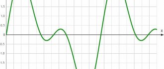
Triangle signals
Triangle signals are generally bidirectional, non-sinusoidal signals that oscillate between positive and negative peak values. A triangle waveform is a relatively slowly rising and falling voltage at a constant frequency. The rate at which the voltage changes direction is equal for both halves of the period, as shown below.
Typically, for triangular signals, the duration of the signal's rise is equal to the duration of its fall, thereby giving a 50% duty cycle. By setting the amplitude and frequency of the signal, we can determine the average value of its amplitude.
In the case of an asymmetrical triangular waveform, which we can obtain by changing the rate of rise and fall by different amounts, we have another type of signal known as a sawtooth waveform.
Ramp signal
A ramp wave is another type of periodic waveform. As the name suggests, the shape of this signal resembles the teeth of a saw. A sawtooth signal can be a mirror image of itself, having either a slow rise but a very steep fall, or an extremely steep, nearly vertical rise and a slow fall.
The slow-rising ramp wave is the more common of the two waveform types, being almost perfectly linear. The sawtooth waveform is generated by most function generators and consists of a fundamental frequency (f) and even harmonics. This means, from a practical point of view, that it is rich in harmonics, and in the case of, for example, music synthesizers, produces high-quality sound without distortion for musicians.