Protective grounding is a system in which conductive parts of equipment that are not normally energized are connected to the neutral. For protective purposes, a connection is deliberately created between open conductive elements of a solidly grounded neutral (in three-phase current networks).
In single-phase current networks, contact is made with the solidly grounded terminal of the single-phase current source, and in the case of direct current - with the solidly grounded point of the current source. Although grounding has serious drawbacks, the system is still widely used in many applications for current protection.
Grounding and zeroing, what is the difference?
There are differences between these two methods:
- when grounding, excess current and voltage generated on the housing are diverted directly into the ground, and when grounded, they are reset to zero in the panel;
- grounding is a more effective way to protect people from electric shock;
- when using grounding, safety is achieved due to a sharp decrease in voltage, and the use of grounding ensures that the section of the line in which a breakdown occurred on the housing is switched off;
- When performing grounding, in order to correctly determine the zero points and choose a protection method, you will need the help of a specialist electrician, and any home craftsman can make grounding, assemble a circuit and deepen it into the ground.
Grounding is a system for removing voltage through a triangle located in the ground made of a metal profile welded at the joints. A properly constructed circuit provides reliable protection, but all rules must be followed. Depending on the required effect, grounding and grounding of electrical installations are selected. The difference between grounding is that all elements of the device that are not under current in normal mode are connected to the neutral wire. Accidental contact of a phase with zeroed parts of the device leads to a sharp jump in current and shutdown of the equipment.
The resistance of the neutral neutral wire is in any case less than the same value of the circuit in the ground, therefore, when grounding, a short circuit occurs, which is, in principle, impossible when using an earth triangle. After comparing the operation of the two systems, it becomes clear what the difference is. Grounding and grounding differ in the method of protection, since there is a high probability of the neutral wire burning out over time, which must be constantly monitored. Grounding is used very often in multi-storey buildings, since it is not always possible to arrange reliable and complete grounding.
Grounding does not depend on the phase phase of the devices, while the grounding device requires certain connection conditions. In most cases, the first method prevails in enterprises where safety requirements require increased safety. But even in everyday life, recently a circuit has often been installed to discharge the excess voltage that arises directly into the ground; this is a safer method.
Grounding protection directly concerns the electrical circuit; after an insulation breakdown, due to the flow of current into the ground, the voltage is significantly reduced, but the network continues to operate. When zeroed, a section of the line is completely switched off.
Grounding in most cases is used in lines with an insulated neutral in IT and TT systems in three-phase networks with voltages up to 1 thousand volts or above this figure for systems with a neutral in any mode. The use of grounding is recommended for lines with a solidly grounded neutral wire in networks TN-CS, TN-C, TN-S with available N, PE, PEN conductors, this shows what the difference is. Grounding and grounding, despite their differences, are systems for protecting people and devices.
How to distinguish between working zero and protective grounding
Of course, you should not check the resistance between the “neutral” and “ground” wires, especially if the power system is energized. No one will let you into the common control room either. Therefore, we will check the correctness of the separation of zero and ground using a multimeter (household tester).
Since the input points of grounding devices (zero at the substation and the grounding bus in the house) are located at a distance from each other, there is a certain resistance between them. The soil, even wet, is not an ideal conductor. If we organize an electrical circuit without a load, we will see the difference in potentials.
We connect the measuring device to the phase contact and the working zero. In the diagram this will be circuit “A”. We fix the value.
We immediately connect the tester to the phase wire and the protective zero contact. In the diagram this is circuit “B”. There is no difference in potential: the device will record the same voltage value. Why did it happen? When the working and protective zeros are combined, the current in both measurement options actually flows through the same wire. The resistance does not change, there are no losses, and there is no voltage drop.
If your measurement results show the same voltage, the wiring is connected in violation of the Electrical Installation Rules.
What happens when the working field and protective grounding are separated?
When the device is connected to phase and zero, there is practically no voltage drop (in the diagram this is circuit “A”). You will see the actual value of the operating voltage in the network. By connecting the tester to the phase wire and protective ground, you measure the potential in a long circuit. To complete the circle, an electric current (circuit “B” in the diagram) passes through the real ground between the physical contact points of the “ground”. Considering the soil resistance, a voltage drop of 5% to 10% will occur. The device will show a lower voltage.
This indicates that your electrical wiring is organized correctly, you have a true distributed protective ground. With properly selected machines, electrical equipment and users are reliably protected.
We figured out what the difference is between grounding and neutralizing. The benefits of proper organization of power supply are obvious.
Explain the purpose and operating principle of protective grounding (with diagrams)
Protective grounding is an intentional electrical connection to the ground or its equivalent of metallic non-current-carrying parts that may be energized.
The purpose of protective grounding is to eliminate the risk of electric shock to people when voltage appears on the structural parts of electrical equipment, i.e. when shorted to the body.
The operating principle of protective grounding is to reduce touch and step voltages caused by a short circuit to the housing to safe values. This is achieved by reducing the potential of grounded equipment, as well as by equalizing potentials by raising the potential of the base on which a person stands to a potential close in purpose to the potential of grounded equipment.
The scope of application of protective grounding is three-phase three-wire networks with voltages up to 1000V with an isolated neutral and above 1000V with any neutral mode.
Fig.1 Schematic diagrams of protective grounding:
a – in a network with an isolated neutral up to 1000V and above
b – in a network with a grounded neutral above 1000V
1 – grounded equipment;
2 – protective grounding conductor
3 – working grounding conductor
rв and ro – resistance of protective and working grounding, respectively
Iв – ground fault current
A grounding device is a combination of grounding conductors - metal conductors in direct contact with the ground, and grounding conductors connecting the grounded parts of the electrical installation to the grounding conductor. There are two types of grounding devices: remote and contour.
A remote grounding device is characterized by the fact that its grounding conductor is located outside the site on which the grounded equipment is located, or is concentrated on some part of this site.
This type of grounding device is used only for low values of ground fault current and, in particular, in installations with voltages up to 1000V, where the grounding potential does not exceed the permissible touch voltage. The advantage of this type of grounding device is the ability to choose the location of the electrodes with the lowest soil resistance.
A loop grounding device is characterized by the fact that its single grounding conductors are placed along the contour of the site on which the equipment being grounded is located, or distributed as evenly as possible over the entire site.
Safety with a contour grounding electrode is ensured by equalizing the potential in the protected area through the appropriate placement of single grounding electrodes.
Indoors, potential equalization occurs naturally through metal structures, pipelines, cables and similar conductive objects connected to an extensive grounding network.
Protective grounding is required for metal non-current-carrying parts of equipment that, due to faulty insulation, may be energized and which may be touched by people. At the same time, in rooms with increased danger and especially dangerous conditions for electric shock, as well as in outdoor installations, grounding is mandatory at a rated voltage of the electrical installation above 42V AC and above 110V DC, and in rooms without increased danger - at a voltage of 380V and above AC and 440V and above DC. Only in explosive areas is grounding carried out regardless of the purpose of the installation.
There are artificial grounding electrodes, intended exclusively for grounding purposes, and natural ones, metal objects located in the ground for other purposes.
For artificial grounding electrodes, vertical and horizontal electrodes are used. As vertical electrodes, steel pipes with a diameter of 3...5cm and steel angles with dimensions from 40*60 to 60*60mm and a length of 2.5...,m are used.
The following can be used as natural grounding conductors: water supply and other metal pipelines laid in the ground, with the exception of pipelines of flammable liquids, flammable or explosive gases, as well as pipelines coated with insulation to protect against corrosion. Natural grounding conductors, as a rule, have low resistance to current flow, and therefore their use for grounding purposes provides great savings. The disadvantages of natural grounding electrodes are their accessibility to non-electrical personnel and the possibility of disrupting the continuity of the connection of extended grounding electrodes.
How to connect grounding
Hello, dear readers of the site sesaga.ru. In this article we will figure out how to connect grounding . This topic is quite extensive and has many nuances, and here you can’t just say - do it this way or connect it here. Therefore, so that you understand me, and it is easier for me to explain to you, there will be both theory and practice.
Grounding is an integral part of our modern life. Of course, you can do without grounding, after all, how long have we lived without it. But, with the advent of modern household appliances, grounding is simply a prerequisite for protecting a person from electric shock.
General concepts
Grounding
– intentional electrical connection of any point in the network, electrical installation or equipment with a grounding device.
Grounding is designed to drain leakage currents
arising on the body of electrical equipment during emergency operation of this equipment, and
providing conditions
for immediate disconnection of voltage from the damaged section of the network by triggering protective and automatic shutdown devices.
For example: an insulation breakdown occurred between the phase and the housing of the electrical equipment - some phase potential appeared on the housing.
If the equipment is grounded, then this voltage will flow through the protective grounding, which has low resistance, and even if the protective shutdown device does not work, then when a person touches the housing, the current that remains on the housing will not be dangerous to the person. If the equipment is not grounded, all the current will flow through the person.
Advice
Grounding consists of a ground electrode
and
a grounding conductor
connecting
the grounding device
to
the grounded part
.
Ground electrode
is a metal rod, most often steel, or another metal object that has contact with the ground directly or through an intermediate conducting medium.
Grounding conductor
– this is a wire connecting the grounded part (equipment housing) to the ground electrode.
Grounding device
– this is a set of grounding conductors and grounding conductors.
A little theory
You have all seen small brick structures in the courtyards into which power cables enter and exit - these are transformer substations
(electrical installations).
Transformer substations are used to receive, convert and distribute electrical energy.
Any substation has a power transformer used to convert voltage, distribution devices and automatic control and protection devices.
Accepting high voltage network voltage 6 – 10 kV
(kilovolt) the substation converts it and transmits it to the consumer - that is, to us.
0.4 kV
or
400 Volts
goes to the consumer .
To power single-phase home equipment (TV, refrigerator, iron, computer, etc.), one of the three phases L1
;
L2
;
L3
and
neutral working
conductor “
N
”.
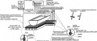
Arrangement of protective current taps when working with three-phase electrical equipment
Switching three-phase electricity consumers differs from connecting conventional household electrical equipment, therefore the installation of protective systems is carried out in a different way. In this case, you should not confuse the neutral or ground wire involved in the control system, that is, involved in the start-up and stop circuit of the unit, with the protective conductor designed to divert a dangerous discharge to the ground.
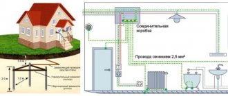
Design, wiring, connection of electrical equipment
The work is carried out in several stages:
- A separate line (route) is installed along the perimeter of the room, made of a narrow metal strip 40x3 mm or copper wire with a cross-section of 16 mm2.
- A busbar (preferably copper) with contact devices (studs or holes for bolted connections) is mounted on it in a hidden place. It is possible to use a metal bus, but in this case welding the studs is a prerequisite.
- This line is connected to a grounding or grounding circuit, which is led out by a separate wire from the switchboard and has a reliable connection to the ground either directly or through a working zero
- The housings of all consumers (three-phase electric motors) are connected via a copper wire to the described bus.
If a short circuit occurs from a voltage leak due to an insulation failure or a “breakthrough” of one of the phases onto the body of grounded electrical equipment, the current will immediately flow into the ground along the path of least resistance, that is, through the conductor connected to the working zero or ground. This will protect a person from electric shock when touching the body of the device.
A grounding device is allowed only if it is not possible to switch with the ground loop. In all other cases, only protective grounding is considered correct.
The unit is connected through a copper wire to a bus mounted from the grounding path
Mandatory use of additional protective devices
The described grounding and neutralizing systems are effective when significant leaks or short circuits occur on the housing of electrical appliances. However, to achieve complete safety when servicing equipment, it is necessary to use additional means of protection to ensure that the electrical circuit is broken when malfunctions occur.
At manufacturing enterprises, these can be automation units (insulation monitoring of BKI or maximum current protection). But the most common means, both in production and in everyday life, are circuit breakers and residual current devices, which:
- will ensure that the electrical circuit is de-energized in case of problems;
- protect the user from electric shock;
- will protect equipment from fire.
Such devices can be designed for single-phase or three-phase systems. They are:
- single-pole - installed on one of the lines (zero, phase);
- bipolar - installed on both wires of the electrical wiring;
- multi-pole (three or more) – used for three-phase voltage.
Household wiring diagram with PE grounding conductor and VA and RCD protection
The circuit breaker switches off when the current load exceeds the rated value indicated on the device body. The RCD monitors the state of the electrical network and is triggered when the slightest current leakage occurs.
Zeroing: purpose and characteristics
Grounding instead of grounding is often used in apartments where there is no traditional grounding system or it has an outdated appearance. This type of protection involves connecting metal parts that do not conduct current with a solidly grounded neutral conductor. This mechanism is designed so that when the insulation is damaged and current exits to the device body, a short circuit occurs, as a result of which circuit breakers and RCDs are triggered.
Important! When practicing grounding instead of grounding, be sure to install automatic circuit breakers and residual current devices. You should carefully and regularly check the neutral wire, since in the event of a high current output, all devices that are grounded are energized
This situation is explained by the automatic switching of zeroed devices to phase. Therefore, for safety reasons, it is not recommended to connect automatic devices and other protective equipment to zero. However, you can completely protect yourself from electric shock only by installing repeated grounding conductors for every 200 m of the electrical network
You should carefully and regularly check the neutral wire, since in the event of a high current output, all devices that have been grounded are energized. This situation is explained by the automatic switching of zeroed devices to phase. Therefore, for safety reasons, it is not recommended to connect automatic devices and other protective equipment to zero. However, you can completely protect yourself from electric shock only by installing repeated grounding conductors for every 200 m of the electrical network.
IT isolated neutral system
In IT, the neutral does not physically have contact with the ground or does, but through devices with high resistance, and the current-carrying elements of the system are grounded.
IT stands for:
I – (from English isolation) isolated neutral;
T – indicates the presence of local (local) grounding of parts of electrical installations;
In such systems, the leakage current to the frame or ground will be quite low and will not affect the operation of the equipment.
IT is used in special-purpose installations with increased requirements for reliability and safety (for example, in hospitals for emergency power supply).
Grounding
The concept of grounding includes structures connecting installations that use electricity to the ground. Due to this, when touching a live surface, the charge received by a person is minimized.
This method is used only in electrical equipment with an insulated neutral. Due to the connection of the ground to the installation body, if the insulation is damaged, the current should flow through the grounding part due to lower resistance.
Grounding a private house
Another function performed by grounding is to increase the emergency fault current. This is necessary so that the protective electrical device is triggered when non-current-carrying parts become energized. This is due to the fact that the grounding installation, which has a sufficiently high level of resistance, may not have enough fault current. This situation is dangerous because, despite the emergency condition of the equipment, the protection does not work and the risk of injury to working personnel remains high.
The grounding device in its structure is one or a whole group of conductors that connect current-carrying elements to the ground. There are several main types of grounding:
- Working type. The main purpose is to ensure uninterrupted operation of electrical equipment both during normal operation and during emergency operation.
- Protective type. Designed to ensure safety when working with electrical installations. The main cause of danger in equipment is the breakdown of a live wire onto the working surface or housing.
- Lightning protection type. The main purpose is to divert a lightning discharge that enters a lightning arrester or lightning rod.
In addition to the division into types, grounding devices differ in the following:
- Artificially manufactured grounding. This type of structure is made specifically to provide protection against voltage. They consist of elements such as metal wires and rods, substandard pipes, and steel corner fixtures.
- Natural grounding. This category includes structures made of metal, but not originally intended to provide voltage protection. Typically, casing pipes, pipelines, and reinforced concrete structures are used as natural grounding.
Grounding identification mark
It is worth noting that the natural type of grounding is used subject to certain rules. The main one is a ban on the operation of structures that are designed to transmit flammable liquids or gases. Also, conductors made of aluminum or pipes, the surface of which is covered with an anti-corrosion layer of insulation, are not suitable for the above purpose.
Main differences
First of all, it should be noted that grounding and grounding have completely different purposes and actions. The main difference between these protective measures is their purpose. Grounding is a more effective and reliable way to protect a residential building from a power surge than the grounding method. The difference in their purpose allows you to choose from them the method of protection that is more suitable in a particular situation. You can immediately install both protection options in a residential building. However, it should be noted that usually preference is given to grounding, considering that this method is necessary in any case.
Grounding allows you to create network protection and quickly reduce the AC voltage in the network to a normal stable value. Whereas grounding will facilitate a faster shutdown of the circuit that was energized, where the fault actually occurred on the line. Also a big difference is the fact that the methods of their installation have varying degrees of complexity.
Creating a grounding connection in a residential building and connecting special equipment requires deeper knowledge of electrical engineering. For this protection method to work correctly, you need to do everything right
Determining the zeroing point is very important, since otherwise there may be negative consequences. When installing protective ground loops, it is enough to follow clear instructions or instructions
Their design is quite simple.
The grounding method does not depend on the phase pattern of electrical appliances and various devices, since they have the same installation diagram. Also, grounding schemes have a greater variety, in contrast to grounding, which allows you to choose a more suitable option in a particular situation. Another difference between them is that directional grounding ensures equalization of potentials, and grounding reacts to such a change by de-energizing the network.
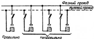
Errors in the implementation of zeroing [edit | edit code]
It is sometimes believed that grounding to a separate circuit not connected to the neutral wire of the network is better, because in this case there is no resistance of a long PEN conductor from the consumer's electrical installation to the ground electrode of the KTP (complete transformer substation). This opinion is erroneous, because the grounding resistance, especially a homemade one, is much greater than the resistance of even a long wire. And when a phase is shorted to the body of an electrical appliance grounded in this way, the circuit current, due to the high resistance of the local grounding, may be insufficient to trigger the circuit breaker (circuit breaker) or the fuse protecting this line. In this case, the device body will be at dangerous potential. In addition, even if you use a small rated AV, triggered by a ground fault current, it is still practically impossible to ensure the time required by the PUE for automatic shutdown of the damaged line.
Therefore, earlier, before the widespread use of RCDs, grounding the housings of electrical receivers without grounding them (that is, grounding according to the TT system) was not allowed at all. Clause 1.7.39 PUE -6:
The directed movement of charged particles, which is called electric current, provides a comfortable existence for modern man. Without it, production and construction facilities do not operate, medical devices in hospitals do not operate, there is no comfort in the home, and city and intercity transport is idle. But electricity is a servant of man only in case of complete control; if charged electrons can find another path, then the consequences will be disastrous. To prevent unpredictable situations, special measures are used, the main thing is to understand what the difference is. Grounding and grounding protect a person from electric shock.
The directional movement of electrons follows the path of least resistance. To avoid the passage of current through the human body, it is offered another direction with the least loss, which provides grounding or grounding. What is the difference between them remains to be seen.
Methods of protection against dangerous potentials
The situation with damage to the phase-to-phase insulation of electrical equipment is instantly stopped by protective devices: circuit breakers or fuses. But it only indirectly poses a danger to humans.
What is more dangerous for people is a single-phase short circuit, as a result of which the housings of electric motors, electrical cabinets, and cable structures become energized.
To eliminate the risk of electric shock , it is necessary that when voltage comes into contact with the housing, a guaranteed short circuit occurs and the potential on the housing is reduced as much as possible.
The first protective effect is achieved by creating a circuit between the housing and the grounded neutral of the electrical installation. When a short circuit occurs, a current is generated that is large enough to trigger the same protective devices that operate during phase-to-phase faults. This is called protective shutdown.
To implement the second method, all potentially dangerous metal parts of electrical equipment are given ground potential. This is done by deliberately connecting them to a grounding device. The event is called protective grounding.
Grounding systems for electrical installations up to 1000 V received classification in the 7th edition of the PUE. Let's consider these systems in turn.
Grounding and grounding in alternating current circuits
Essentially, zero is a blue wire marked N. Grounding is a deliberate connection of either the midpoint in the winding of a 3-phase generator, or a connection in the load to the operating zero. Zeroing has two main functions: 1 – working function and 2 – protective function. The operating function is most clearly manifested in the electrical distribution diagram in an apartment building. Initially, electricity is supplied only using three-phase current, which is evenly distributed throughout the apartment. As an example, let's say that there are 36 apartments in one specific entrance. Therefore, the load distribution should be done as balanced and evenly as possible: we connect 12 apartments to phase A, 12 apartments to phase B, and, naturally, the remaining 12 apartments to phase C. No matter how hard designers try to balance the consumption pattern, practice clearly shows that it is never possible to achieve balance and load uniformity 100% - some spend more electricity, and some less. That's why line N was invented - working zero. The main purpose of the working zero is to restore the voltage balance across phases, that is, to prevent voltage imbalances from occurring. By the way, it is the sudden disconnection of the neutral conductor that can lead to the fact that in some apartments there will be a lightning-fast surge in operating voltage up to 380 V. In the jargon of electricians, this phenomenon is called burnout or zero drop.
A three-phase system requires grounding and grounding of the midpoint of the working windings connected in a star configuration. To clearly understand the difference between grounding and grounding, let's turn to the standard diagram for connecting a load to a three-phase power source using a Y (star) circuit. If we consider a three-phase transformer, a three-phase asynchronous electric motor, a three-phase furnace as a load, then the system will function when connected using three wires with phases A, B, C and a neutral wire N. In fact, if we consider electrical installations in production, then the presence of a fourth conductor performs purely protective functions. When the insulation of the windings of a three-phase electric motor breaks down, a high potential rushes to the body of the device, which is in direct galvanic connection with wire N, that is, the working zero. Consequently, with such a connection, a short circuit will occur, which will cause the three-phase circuit breaker to turn off.
Systems with solidly grounded neutral TN grounding system
Such systems include:
- TN-C;
- TN-S;
- TNC-S;
- TT.
According to clause 1.7.3 of the PUE, a TN system is a system in which the neutral of the power source is solidly grounded, and the open conductive parts of the electrical installation are connected to the solidly grounded neutral of the source through neutral protective conductors.
TN includes elements such as:
- grounding electrode of the middle point, which relates to the power source;
- external conductive parts of the device;
- neutral type conductor;
- combined conductors.
The source neutral is solidly grounded, and the external conductors of the installation are connected to the solidly grounded midpoint of the source using protective type conductors.
It is possible to make a grounding loop only in electrical installations whose power does not exceed 1 kV.
TN-C system
In this system, the neutral protective and neutral working conductors are combined into one PEN conductor. They are combined throughout the system. The full name is Terre-Neutre-Combine.
Among the advantages of TN-C, one can highlight only the easy installation of the system, which does not require much effort and money. Installation does not require improvement of already installed cable and overhead power lines, which have only 4 conducting devices.
Flaws:
- the likelihood of receiving an electric shock increases;
- it is possible that line voltage may appear on the body of the electrical installation during an electrical circuit break;
- high probability of loss of the grounding circuit in case of damage to the conductive device;
- This system only protects against short circuits.
TN-S system
The peculiarity of the system is that electricity is supplied to consumers through 5 conductors in a three-phase network and through 3 conductors in a single-phase network.
In total, 5 conductive sources leave the network, 3 of which serve as the power phase, and the remaining 2 are neutral conductors connected to the zero point.
Design:
- PN is a neutral mechanism that is involved in the circuit of electrical equipment.
- PE is a solidly grounded conductor that performs a protective function.
Advantages:
- ease of installation;
- low cost of purchasing and maintaining the system;
- high degree of electrical safety;
- no contour creation required;
- the ability to use the system as a current leakage protection device.
TN-CS system
The TN-CS system involves dividing the PEN conductor into PE and N in some part of the circuit. Usually the separation occurs in the panel in the house, and before that they are combined.
Advantages:
- simple design of a protective mechanism against lightning strikes;
- availability of short circuit protection.
Disadvantages of use:
- poor level of protection against burning of the neutral conductor;
- possibility of phase voltage occurrence;
- high cost of installation and maintenance;
- the voltage cannot be turned off automatically;
- There is no protection against current in the open air.
TT system
TT is designed to provide a high level of safety. Installed in power plants with a low level of technical condition, for example, where bare wires are used, electrical installations that are located in the open air or mounted on supports.
TT is mounted according to a four-conductor circuit:
- The 3 phases supplying voltage are shifted at an angle of 120° to each other;
- 1 common zero performs the combined functions of a working and protective conductor.
TT advantages:
- high level of resistance to deformation of the wire leading to the consumer;
- short circuit protection;
- Possibility of use on high voltage electrical installations.
Flaws:
- complex lightning protection device;
- inability to track the phases of a short circuit in an electrical circuit.
Types of grounding systems
The classification of types of grounding systems is given as the main characteristics of the supply electrical network. GOST R 50571.2-94 “Electrical installations of buildings. Part 3. Basic characteristics" regulates the following grounding systems: TN-C, TN-S, TN-CS, TT, IT. TN-C system
The TN-C system (French Terre-Neutre-Combine) was proposed by the German concern AEG in 1913. The working neutral and the PE conductor (Protection Earth) in this system are combined into one wire. The biggest drawback was the possibility of phase voltage appearing on the housings of electrical installations in the event of an emergency zero break. Despite this, this system is still found in buildings in the countries of the former USSR.
TN-S system
Separating zeros in TN-S and TN-CS
To replace the conditionally dangerous TN-C system, the TN-S system (French Terre-Neutre-Separe) was developed in the 1930s, in which the working and protective zeros were separated directly at the substation, and the ground electrode was a rather complex structure of metal fittings. Thus, when the working zero was broken in the middle of the line, the electrical installation housings did not receive line voltage. Later, such a grounding system made it possible to develop differential circuit breakers and current leakage circuit breakers capable of sensing small currents. Their work to this day is based on Kirchhoff’s laws, according to which the current flowing through the phase wire must be numerically equal to the current flowing through the working zero.
You can also observe the TN-CS system, where the separation of zeros occurs in the middle of the line, however, if the neutral wire breaks before the separation point, the housings will be under line voltage, which will pose a threat to life if touched.
TN-CS system
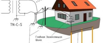
In the TN-CS system, the transformer substation has a direct connection of live parts to the ground. All exposed conductive parts of the building's electrical installation are directly connected to the grounding point of the transformer substation. To ensure this connection, a combined neutral protective and working conductor (PEN) is used in the section between the transformer substation and the electrical installations of the building; in the main part of the electrical circuit, a separate neutral protective conductor (PE) is used.
TT system
In the TT system, the transformer substation has a direct connection of live parts to the ground. All open conductive parts of the building's electrical installation have a direct connection to the ground through a ground electrode, electrically independent from the neutral ground electrode of the transformer substation.
IT system
In an IT system, the neutral of the power supply is isolated from earth or earthed through high resistance instruments or devices, and the exposed conductive parts are earthed. The leakage current to the frame or to ground in such a system will be low and will not affect the operating conditions of the connected equipment. The IT system is used, as a rule, in electrical installations of buildings and structures for special purposes, which are subject to increased reliability and safety requirements, for example, in hospitals for emergency power supply and lighting.
Grounding is a deliberate electrical connection of open conductive parts of electrical installations that are not normally energized with a solidly grounded neutral point of a generator or transformer in three-phase current networks; with a solidly grounded output of a single-phase current source; with a grounded source point in DC networks, performed for electrical safety purposes. Protective grounding is the main measure of protection against indirect contact in electrical installations up to 1 kV with a solidly grounded neutral.
Electrical installation Ivanovo - Zeroing: will it protect or kill?
Zeroing – will it protect or kill?
Hello, friends!
In this article we will talk about what zeroing is, where it is used, as well as the main errors in its design. The topic is not easy, and there are constant debates on forums.
It is interesting that often even electricians cannot correctly say how grounding differs from grounding. Let's figure it out. First, let's see what the PUE says about zeroing.
Simply put, grounding is the connection of the body of an electrical device with the neutral wire.
Now let's see what the PUE tells us about grounding
note
Grounding of any part of an electrical installation or other installation is the intentional electrical connection of this part to a grounding device.
In simple words, grounding is the connection of the body of an electrical device with a ground electrode. A ground electrode is a structure made of metal pins driven into the ground.
Now let's look at how the most common power supply systems for apartment buildings work.
Old, Soviet TN-C system
More modern TN-CS system
Both schemes use a combined neutral conductor PEN, which is grounded at the transformer substation.
The main difference between them is that in TN-CS the combined conductor is divided into a working zero and a protective conductor. This is done in the introductory common building panel (ACB). In this case, re-grounding must be done.
If you look closely at the diagrams, it becomes clear that the working zero is always connected to ground, that is, grounded. And the question arises: what, exactly, is the difference between grounding and grounding? After all, by connecting the body of the device to the working zero, we actually connect it to the ground.
In fact, there is a difference. It lies in the principle of action.
Grounding is designed to drain current to ground. This reduces the dangerous voltage on the body of the device or device.
Grounding is intended to create a short circuit effect during phase breakdown on the housing. At the same time, the machine is activated and turns off the emergency line.
Important
Thus, grounding and grounding in TN systems work simultaneously, so to speak, in one bottle. Therefore, the 3rd protective contact in Euro sockets in TN systems is both grounding and neutralizing.
Based on this, it is correct to talk about a combined conductor PEN, a working neutral conductor N and a protective conductor PE. At the same time, even electricians do not always understand the difference between PE and N, but it is very significant.
Usually, when some “electrician Uncle Vasya” talks about grounding, he means various kinds of collective farms such as jumpers in sockets and the like connecting the protective wire to the neutral wire. And it's dangerous.
Incorrect zeroing can, instead of protection, cause a tragedy. And such pseudo-protection occurs very, very often.
Let's figure out how protective grounding is done correctly and what absolutely should not be done.
Remember, the division of the combined conductor into a working zero and a protective zero must be done in a common house input device (IDU). And from there the protective conductor must go to the floor panels, and from them to each apartment.
Thus, we get a five-wire riser: 3 phases, working zero and protective zero. In this case, we are not talking about the so-called grounding, since each apartment receives a separate protective wire (TN-CS and TN-S systems). It needs to be connected to the third contact of the sockets.
In old houses with non-modernized wiring, there is usually a four-wire riser: 3 phases and a combined neutral PEN (TN-C system). This is where the complete chaos and terrible mistakes begin.
Advice
It all starts in the floor panel. Often it makes an independent division of PEN into PE and N.
This option has the right to life, but only if important rules are observed. Here are the main ones:
Rule 1. In single-phase circuits, it is prohibited to separate the neutral wire (PUE - 1.7.132).
How to determine which network is in your home? In relatively old houses, the access risers are four-wire: three phases and one combined neutral (PEN). That is, three-phase risers are used, respectively a three-phase circuit.
In very old houses, Stalin and Khrushchev buildings, a two-wire riser is often used, in which there is only a phase and a working zero. A distinctive feature of such houses is the absence of access panels. The risers go in the shafts between the apartments, and in the apartments themselves there are specific “humpbacked” shields. In such houses, as a rule, a single-phase network is used.
Rule 2. The combined PEN conductor must have a cross-section of at least 16 mm for aluminum or 10 mm for copper.
That is, the zero riser must have a cross-section no less than the specified one. In many houses the cross-section is smaller; in this case, it is impossible to divide the combined zero into protective and working. If you have a Soviet-built house with gas stoves, then in 80% of cases the riser in it is weak.
Rule 3: Once PEN is split into PE and N, they cannot be reconnected.
Here, I think, no explanation is needed.
Rule 4. The protective conductor PE must not be disconnected.
That is, you cannot install machine guns and other disconnecting devices on it.
Rule 5. PEN must be separated BEFORE all machines, switches, switches.
It’s better to do this: take a brass busbar and screw it to the shield so that there is contact between them. Make a branch from the zero riser through a separate nut to this bus. Connect the PE protective wires from the apartments to the bus.
If at least one of these rules is not followed, then it will not be protection, but a life-threatening collective farm.
A little more about what not to do
1) Connect the protective and neutral contacts in the socket with a jumper. This is one of the most dangerous mistakes!
note
If the zero burns out, is damaged, or is accidentally disconnected, dangerous phase voltage will immediately appear on the housing of all devices connected to such sockets. In this case, neither the RCD nor the machine will work. Hello death.
The same effect will occur with a random change of phase and zero.
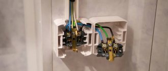
2) Place the neutral and protective conductors on one screw in the shield
PE and N must be on different terminals (busbars). Moreover, each wire from a separate apartment must be clamped with a separate screw.
3) Zero to an ungrounded (non-zeroed) shield.
Typically, all panels have direct contact with the zero or protective riser (zeroed). But sometimes there is no contact, for various reasons. For example, the connecting wire fell off. Grounding such a shield can lead to the appearance of dangerous voltage on its body.
In practice, this kind of jambs are found all the time, in various variants and combinations. I can advise you not to be lazy, study the PUE, and also not trust your wiring to dubious individuals.
Source: https://elektro.ivmast.ru/zanulenie-zashchitit-ili-ubet
What is electricity
To understand for ourselves what electrical safety, protective grounding, grounding are, and how it all works, let us recall the essence of the phenomenon of electric current.
All bodies in the Universe consist of atoms, the structure of which is known to every schoolchild: a positively charged nucleus inside and negative electrons rotating around the nucleus. There are a number of chemical elements - metals - in which several electrons located in the orbits farthest from the nucleus can easily be torn off (attracted by a strong positive charge).
Thus, if you take a metal wire and apply opposite electric charges to its ends, then the electrons, breaking away from their atoms, will begin to move towards the positive charge.
However, when moving through the thickness of the metal, electrons constantly “bump into” atoms, causing them to slightly vibrate at the nodes of the crystal lattices. This leads to the release of heat. Moreover, the heating can be so strong that the metal can heat up to thousands of degrees (like the filament of an incandescent lamp). In some cases, the metal may even melt and even evaporate.
Distinctive features
As it becomes clear, in essence, grounding and grounding perform the same function - they remove residual electricity from the metal parts of any device that consumes current. But they have significant differences. The first technique directs excess current from electrical installations to the ground, and the second - to the transformer. Grounding is most often made of metal rods and is used to relieve excess voltage. Its quality directly depends on how the grounding mechanism circuit is made.
When grounding occurs, the neutral wire is connected to the electrical installation housing. If the housing or ground touches a phase, a sharp increase in current will occur, that is, a short circuit. As a result, the installation is switched off in a timely manner, which is impossible when using a grounding mechanism. Of course, such a remedy is not always effective, and there is a risk that the neutral wire will burn out. To prevent this from happening, regular monitoring of its condition is required. Now it is clear how grounding differs from grounding. Let's look at the advantages of the basic method that is used everywhere today.
Zeroing systems and schemes
There are several options for protecting electrical equipment by grounding the metal casing of the device. In this article we will look at the following two main methods of grounding any equipment connected to a three-phase and single-phase power supply network.
- Three-phase network. For such a connection, the circuit is quite simple and it will not be difficult for anyone familiar with the basics of electrical engineering. In this embodiment, the neutral wire N and the protective line PE are combined into one common bus called PEN. This zeroing method is called the TN-C system. To implement it, it is necessary to strictly comply with the increased requirements for equalizing electrical potentials, as well as for the cross-sectional area of the combined PEN conductor. For networks with a single-phase power supply, the use of the TN-C system is strictly prohibited by the electrical installation rules (PUE).
- Single-phase network. To implement protective grounding in single-phase networks, there is a method using the TN-CS system. With this method, the N conductor is combined with the PE line only in a limited section of the power supply network, starting next to the main power source. The TN-CS system is good for single-phase networks, but in no case should it be used when grounding electrical equipment operating in three-phase electrification networks.
Any protective grounding system can only be used in networks, both single-phase and three-phase, with an alternating voltage of no more than 1 kV, moreover, the network must necessarily have a tightly grounded neutral. After completing work to protect electrical equipment, it is necessary to check and calculate the zeroing system, which should only be entrusted to a specialist, since this procedure involves the use of special instruments. As a result of the measurements, the resistance of the neutral-phase loop is determined, which should have a minimum value.
After this, according to Ohm’s law, according to which I = U/R, the short-circuit current (short circuit) is calculated when a network phase hits the metal body of the device. The value of this parameter should be a certain amount greater than the triggering threshold of automatic electrical de-energization systems. Otherwise, they need to be replaced with devices with a lower response threshold or measures must be taken to reduce the resistance value of the neutral-phase loop. When calculating the short-circuit current, an increasing reliability factor Kn should be used, which is always greater than one.
Popular methods of zeroing
Grounding PNG is characterized by simplicity of design , which is explained by the combination of protective and neutral conductors. The disadvantages of this safety system include increased requirements for the interaction of the conductor cross-section of its potentials. PNG is widely used when it is necessary to ground asynchronous units operating in three-phase networks.
The most popular today are modified systems for grounding electrical installations, which are powered by a single-phase network. They use a common combined PEN conductor connected to a solidly grounded neutral. After this connection, the PE and N cables are separated, which are then connected to the housing or similar protection devices. The advantage of this grounding technology is its versatility, the ability to be used in single-phase and three-phase networks, as well as simplicity of design and complete safety.
Grounding and grounding of electrical installations allows you to protect equipment from power surges and short circuits. Zeroing involves the use of special equipment that allows you to redirect excess voltage to the shield. Such protection is used primarily in industrial enterprises and facilities where increased safety of equipment operation is required. Owners of private houses can carry out grounding themselves, which will allow them to protect themselves and the electrical appliances they use from short circuits and surges in the network.