About grounding in simple words
The very concept of “grounding” comes from the word “earth”, that is, soil or soil, the purpose of which is to serve as a drain for dangerous currents flowing through a specially organized circuit. For its formation, an inextricable connection of all parts of the protective system is necessary, which starts from the point of contact of the body of the grounding element and ends with the element of the grounding device (GD) immersed in the ground.
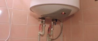
External ground loop of a private house (left). Indoor grounding (right), grounding conductor indicated by dotted line.
According to the definitions given in the technical documentation, grounding is a deliberate electrical connection of the metal housings of units with a special grounding circuit. Based on the facts considered, we can conclude that grounding is the intentional electrical contact of the protected equipment with the ground.
What is neutral?
Neutral is a neutral protective conductor that connects the neutrals of electrical installations in three-phase electric networks. Area of use: grounding electrical installations.
The step-down substation, where the transformer installation is located, is equipped with its own ground loop. This circuit consists of a steel tire and rods buried in a special way in the ground. A cable with 4 cores is laid to the consumption sources in the electrical panel from the substation. When an electricity consumer needs power from a three-phase circuit, all 4 wires must be connected. When different loads are connected to the conductors, a neutral shift occurs in the system; to prevent this shift, a neutral conductor is used. It helps to symmetrically distribute the load across all phases.
Grounding Requirements
After you have figured out what is the definition of the very concept of grounding, you can move on to those categories and norms that are introduced by current standards. According to the PUE, the grounding device is primarily subject to the following requirements:
- the purpose of the charger is to effectively drain dangerous currents into the ground, for which purpose their design includes a whole set of conductors and metal rods;
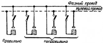
- All parts of the electrical installation, including metal switchboard doors, must be grounded;
- the total contact resistance of the contacts in the grounding system should not exceed 4-30 Ohms;
- when installing it in distributed loads, it is necessary to use a potential equalization system (its purpose is to eliminate uneven voltage distribution).
Additional information: Since the main purpose of grounding is to ensure the safety of personnel working with the equipment, during its operation special attention is paid to the reliability of operation.
The quality of its work is ensured by a whole range of preventive measures and periodically organized tests.
TN-S: effective, but expensive
TN-S, in comparison with the TN-C grounding system, is a more modern, efficient and safe system in which the solidly grounded neutral of the transformer (or generator) is used to connect conductors with a “zero” on the side of the current source. When using it, the risk of high voltage occurring on the housings of electrical equipment is eliminated - even if the power line is damaged.
Meanwhile, there are two reasons why TN-S is not widely used in Russia. The first is that the Russian energy industry is mainly focused on 4-wire, 3-phase power supply circuits. The second reason is the high cost of using the TN-S grounding system.
During installation, when connecting three phases, you will need to use 5 wires to connect the equipment to the power source. For a single-phase connection, 3 wires are required. Due to the prevalence of 4-wire circuits for three phases in Russia, the use of TN-S will be inappropriate, since in this case it will be necessary to extend a separate line consisting of 5 wires from the transformer substation.
The new edition of the PUE, as well as GOST R50571, contains instructions for installing the TN-S system at facilities that require a high degree of electrical safety. Also, these regulatory documents prescribe its arrangement during construction and major repairs of buildings.
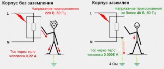
Why does a person get electrocuted?
In order to answer the question posed, you will need to familiarize yourself with the malfunctions that periodically occur in existing electrical equipment. The fact is that during its long-term operation, the insulation may be destroyed and the exposed power supply wire may come into contact with the body of the electrical installation.
If the equipment being operated does not have grounding, this threatens the operator working with it with an electric shock (photo on the left). A similar effect occurs when a person’s body accidentally comes into contact with conductive parts of a washing machine or bathtub, for example.
Norms and requirements
According to the PUE, the following can be used as electrodes:
- strip with a cross section of 48 sq. mm;
- rod - from 10 sq. mm;
- corner with a thickness of 4 mm;
- a pipe with a diameter of 2.5 cm and a wall thickness of 3.5 mm.
These dimensions are adopted in order to ensure the durability of the rods within 5-10 years.
Pin driving depth
According to the PUE (Chapter 1.7.), the minimum immersion depth of the rod is 0.7 m. The strip connecting the vertical grounding conductors is placed on the edge.
Grounding and lightning protection
The PUE prescribes connecting the protective grounding circuits of electrical installations and lightning protection of the second and third categories, i.e. all objects except explosive ones. Communication is carried out by at least 2 conductors (PUE, clause 1.7.55).
If the circuits remain disconnected, a breakdown between the lightning rod and the home electrical network may occur during a lightning strike. This will lead to failure of the electronics, fire or destruction of some elements, incl. plastic water pipes.
Grounding principle
After familiarizing yourself with the definition of grounding systems and the requirements for them, you should understand what grounding is and what it is intended for. To do this, first of all, you should know that a person’s feet through a reinforced concrete floor always have some contact with the ground.
When a person touches the body of equipment exposed to high potential, current flows through his body and legs into the ground, that is, he is a link in this chain.
Please note: Even small currents are dangerous to humans, and when they reach a value of 100 mA, death is possible.
In order to understand how the grounding system works, it should be taken into account that the housing of electrical equipment is connected to the ground (grounded) through a set of conductors and metal pins. Through this intentional connection, the human critical potential is reduced to a safe level. In this case, emergency currents “flow” through the grounded body to the ground, bypassing the human body.
Why do you need an RCD if there is grounding?
An RCD (residual current device) is a high-speed switch that works in tandem with a ground loop and responds to current leakage by breaking the circuit.
Operating principle of RCD Source tirez.ru
Circuit without grounding and RCD
When the insulation of a conductor is broken, a phase appears on the metal body of the electrical device. If the current has nowhere to go further, then when a person comes into contact with the body of an electrical device, the discharge will go through the body. The consequences will depend on many factors and the results can be different - from fear to interruptions in heart function.
Without grounding, the phase on the surface of the device with damaged wiring will remain until the input circuit breaker turns off .
RCD in a circuit without a protective conductor (TN-C)
In such a system, if the conductor insulation is broken, the RCD will not immediately operate, since no leakage current will occur. But as soon as a person touches the damaged device, part of the current will go into the body and the RCD will trip.
Even without grounding, current will flow through the human body only for the time required for the RCD to trip - usually tenths of a second. As a result, painful sensations are possible, but a fatal outcome can most likely be avoided.
Circuit with protective conductor (TN-S and TN-CS) and RCD
If an electrical appliance is in contact with the ground loop and is connected through an RCD, then if the phase conductor shorts to the metal body of the electrical appliance, leak immediately appears (which goes into the ground). The RCD trips and breaks the circuit.
Gas boiler and RCD
First of all, you need to understand that grounding a gas boiler in a private house must be carried out without fail - there are no exceptions.
Grounding the gas boiler and installing the RCD are carried out simultaneously. This is a necessary condition when connecting gas to a residential building, since surface tension forms on the body of the gas boiler during operation.
Grounding a gas boiler in a private home will avoid damage to expensive electronic equipment and prevent fire caused by static electricity. This measure, given the high explosiveness of the gas, serves as additional protection against fire.
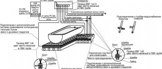
All parts of a gas boiler must be grounded Source pinterest.com
What does the design of the grounding device consist of?
First you should get acquainted with the elements that make up its design. A typical grounding loop is a structure of three steel grounding rods driven into the ground at the corners of a trench dug to a depth of approximately 0.7-0.8 meters. Grounding conductors can be steel angles or copper-plated rods.
The length of the part of the grounding conductors immersed in the soil must be at least 2.5 meters. The exact values of these parameters are selected taking into account the nature of the soil at the location where the circuit is being constructed and the climatic conditions in the area. You can learn more about the grounding loop and its installation in our article “Grounding loop, what it is and how it works.”
Parts of steel blanks protruding from the ground by 10-15 cm are welded together with metal plates 40 mm wide (at least 4 mm thick). In the upper part of one of the vertical electrodes, a contact zone is arranged in the form of a threaded bolt welded onto it. The end of a copper bus coming from the body of the grounded device is attached to it using a nut, the cross-section of which should not be less than 6 sq. mm.
Additional information: To reduce the resistance of the emergency current flow circuit, this connection is sometimes welded.
External ground loop
Upon completion of the main work, the trench with the structure placed in it is filled with previously discarded earth, from which stones and unnecessary debris are removed.
According to the requirements of the PUE, any grounding system must comply with technical standards in terms of the maximum permissible leakage current resistance. Its value should be:
- less than 8 Ohms in industrial networks with phase voltage 220/127 Volts;
- less than 4 Ohms for linear voltages 380 Volts;
- no more than 30 Ohms in household networks (this indicator is considered the maximum permissible).
The copper core laid from the structure of the charger is fixed at its second end on a special strip mounted on the distribution panel of the facility (at home, in particular). It is called the main grounding bus (GGB), and it is intended for assembling all protective conductors in one place. Copper conductors diverge from it directly to consumers (through sockets to device housings).
Grounding systems in a private house: types, differences and design features
Much has already been said about how important a properly installed grounding system is for a private house or cottage. Therefore, there is no particular need to repeat about the danger of electric shock in a house that is not connected to a ground loop. And if you want to ensure the maximum safety of your living space, then the information presented in this article will no doubt be useful to you.
Types of grounding for a private house
Depending on the design features of the power line approaching the house, various grounding systems are used. The following types are distinguished: TN-S, TN-C, TN-CS, TT, etc. Private houses and cottages are usually connected to two types of grounding systems: TN-C-S and TT. And if there is no grounding in your house, then these systems are the easiest to implement in practice; it is them that many craftsmen create on their own, and it is they that will be discussed in this article.
Let us briefly explain what the letters in the names of the systems mean:
- The first character indicates the grounding parameters of the power supply (T - ground, etc.).
- The second symbol (N or T) characterizes the grounding parameters of open parts of household electrical installations. The letter N, for example, denotes grounding or connection of the protective conductor of a home electrical installation with the neutral of the power source (transformer substation).
- The letters S and C indicate a subtype of system in which grounding is carried out through the power source.
Simply put, if the first letters in the designation are TN, then we are talking about a system with a solid grounding of the power source, and the consumer’s electrical system is connected to its neutral through neutral and protective conductors. As we have already said, grounding systems come in several varieties:
- TN-C is a system that has combined neutral and protective conductors. The supply line in this case consists of two- or four-core cables (phase and neutral conductors - in a single-phase power supply system, three phase and one neutral - in a three-phase power supply system). The TN-C system can hardly be called a full-fledged grounding system, because the grounding conductors of the electrical installation in it are connected to the neutral wire coming from the transformer. It is usually called grounding, because it is hardly capable of performing all the functions of a grounding loop.
- TN-S is a system that has separated neutral and protective conductors. The supply line in this case consists of three- or five-core cables (phase, neutral and protective conductors - in a single-phase power supply system, three phase plus neutral and protective conductors - in a three-phase power supply system).
- TN-CS is a system in which the neutral and protective conductor combines their functions only in a certain area, which begins near the power source and ends at the entrance to the house. Here they are divided into neutral protective (PE) and neutral working (N) wires (the protective conductor in such a system is re-grounded). In essence, the TN-CS system is created on the basis of the TN-C.
- TT is a system in which the home power supply system has a separate solid grounding, which is not connected in any way to the grounding of the supply substation.
Grounding in all TN category systems is carried out through a transformer substation, while the TT system involves the creation of a grounding loop directly near the house. One can argue for a long time about which of the two systems is better – TN-CS or TT, so let’s immediately outline the pitfalls of these two systems.
If you are thinking about creating a TN-CS system, then first of all you should make sure of the reliability of the power line supplying electricity to your home. After all, the condition of suburban power lines (and they are, in most cases, overhead) leaves much to be desired. No one can guarantee that one fine day, as a result of an accident on the line (if a flimsy support tilts under its weight, etc.), the exposed neutral wire will not connect to the phase wire. As a result, the zero will burn off from the transformer, and we will get a deadly voltage “walking” through the body of household electrical appliances.
AlexeyL FORUMHOUSE user
For the TN-CS circuit, you must either be completely confident in the safety and reliability of the PEN conductor coming to you on the street, or you must guarantee this safety with your own grounding. Given the typical state of local air networks, the only certainty is the opposite: the unreliability of PEN. And the construction of a grounding system capable of withstanding the zero current of many neighbors in the event of a broken neutral and a large imbalance of loads across phases is a very difficult and expensive task.
Let us explain: PEN is a combined working neutral (N) and protective neutral (PE) conductor connecting the transformer substation with the incoming home panel.
The use of SIP cable as part of the supply line provides some safety guarantees, but if the condition of the ground supports is unsatisfactory, all these guarantees can be called into question. Simply put, it is possible to create a TN-CS type grounding system only if you have full confidence in the reliability of the supply power line.
The TT system in a private house also has its disadvantages. Systems of the presented type require the mandatory presence of residual current devices (RCDs) or circuit breakers in the grounding circuit, which should be regularly checked for operability. To ensure safe operation, the CT must be equipped with potential equalization systems and an artificial grounding loop, the creation of which requires time, effort and certain costs.
In practice, creating a TN-CS system always looks more preferable, but if the condition of the current supply lines is questionable (the supply line is formed by bare conductors, there are frequent breaks, air supports are in poor condition, etc.) it is recommended to create a system as a more reliable alternative TT.
Briefly about the TN-S system
If a TN-S system is connected to the house, then it is enough to equip the input panel with a grounding bus, to which the PE input grounding conductor and protective conductors going to household consumers should be connected. The PE conductor can be connected to a repeated grounding circuit. We will return to the question of how to do this later.
AlexPetrowFORUMHOUSE user
With TN-S, a five-wire line with separate PE and N comes to the consumer. In such a system, nothing needs to be divided.
We are talking about separating the incoming neutral wire, which is supplied to the consumer in TN-C systems and is divided when creating a TN-CS system. A similar division is shown in the diagram.
TN-CS system design
If a TN-C system is suitable for your home, if you have verified that the supply line is in impeccable condition and have made sure that a SIP cable is used as the supply conductor, you can begin to create a TN-CS type grounding system.
The conductor is divided into the protective wire PE (yellow-green) and the neutral wire (blue) in the input panel.
In the shield, re-grounding is connected to the system.
In accordance with the updated edition of the PUE rules, the separation of the PEN conductor must be performed before the input switching protective device and before the electric meter. It is strictly forbidden to include protective and switching devices in the circuit of PEN and PE conductors. You can only break the circuit of conductor N (PUE 1.7.145).
AlexPetrow
Conductors PEN and PE are inseparable! All devices with switching (circuit breakers, circuit breakers, batchers, metering devices, etc.) must be located on the line of conductor N (it can be “torn”, and sometimes necessary).
The PEN conductor is divided according to the following scheme:
For separation, two buses should be used: the main ground bus (GZSh) and the zero bus (N). The main grounding bus is connected to the additional grounding circuit through the panel body, the PEN input cable is connected to it and the grounding terminals of the sockets installed in the house are connected. The following are connected to the N bus: an electric meter, circuit breakers and power terminals of home energy consumption points.
The main grounding bus becomes the PE bus after the jumper connecting the GZSh and N. It is to the PE that an additional grounding circuit and protective conductors leading to the grounding terminals of the sockets are connected.
AlexPetrow
In fact, physically and organoleptically there should be two tires - PE (GZSh) and N. PEN is divided according to the “rule of the Russian letter N” - this is what the correct division looks like. The supply PEN can come to either end of the vertical line (bus), and this line after the jumper will always be PE. The other vertical line will always be N (along its entire length). A jumper is just a jumper. PE is grounded, and protective conductors will be switched on this bus, and N serves as a load current conductor. Once separated, they should not be combined.
The division is shown more clearly in the photo.
In accordance with the rules of the PUE, it is recommended that the main grounding bus be made of copper. The use of steel tires is allowed, but the installation of aluminum tires is strictly prohibited. GZSh and N tires are made from the same material.
stanislav-e88aFORUMHOUSE user
Zero (N) from the separating bus goes to the 2-pole input circuit breaker, then to the counter. From the meter zero to consumers. Double machines are not needed (except for the introductory one). PEN must be split before it. With the phase, everything is simple: it goes to the input machine, then to the meter, then to consumer groups.
The basic requirements for the PEN conductor separation unit are as follows:
- The zero separating bus N must be installed on an insulator, that is, it must be isolated from the panel body, to which the PE bus is additionally connected (after all, after separation, these two buses should not touch anywhere);
- All conductors suitable for dividing busbars must be secured using strong bolted connections, which ensures reliable connection and the ability to disconnect individual conductors;
- The cross-section of the main conductor must be greater than or equal to the cross-section of the PEN supply conductor.
It is recommended to use specialized wires as PE protective conductors. If the PE conductors and phase conductors are made of the same material, then the dependence of the minimum PE cross-section on the phase conductor cross-section will be as follows.
The “£” sign in this case means “≤”.
If the protective and supply conductors are made of different materials, then the PE cross-section must be equivalent in conductivity to the cross-section of the phase wires discussed in the table.
The minimum cross-section of the combined conductor in the TN-C system must correspond to the following values: 10 mm² for copper conductors and 16 mm² for aluminum. If the cross-section of the conductor is smaller, then it is prohibited to separate it! In this case, you should resort to creating a TT system.
Re-grounding and residual current devices in TN-CS systems
If you want to protect yourself and your family as much as possible from damage by leakage currents, then the TN-CS grounding system should be equipped with residual current devices (RCDs) or differential circuit breakers. In accordance with the recommendations of the updated edition of the PUE (Vol. 7), TN type systems equipped with residual current devices (RCDs) must be connected to re-grounding, which is mounted at the entrance to the house.
SB3FORUMHOUSE user
It is required to perform repeated grounding at the ends of overhead lines and branches from them with a length of more than 200 m, as well as at the inputs of overhead lines to electrical installations, in which protective automatic power off is performed as a protective measure against electric shock due to indirect contact.
If RCDs are not used in your system, and there is already re-grounding within 200 m of your panel, then there is no particular need to create additional grounding at the entrance to the house.
Crazy CatFORUMHOUSE user
If there is already re-grounding at a distance of 200 m from the input, or the input is made with a cable laid in the ground, there is no need for re-grounding.
About RCDs: for additional protection against leakage currents due to indirect contact with open surfaces of electrical appliances, it is recommended to introduce residual current devices (RCDs) or differential circuit breakers into the general power supply circuit. Such protection is triggered by weak leakage currents, turning off the power supply to the network (leakage currents, despite their small magnitude, can be dangerous to humans). Their installation is advisable for the reason that conventional circuit breakers operate only on short-circuit currents.
In modern systems, it is customary to install RCDs of two different ratings: a general fire-fighting RCD that triggers a leakage current of 100 mA, as well as one (or several) RCDs connected to a line of plug sockets and triggered by a current of 30 mA or 10 mA.
RCDs connected to household appliances that directly interact with water (washing machines, dishwashers, water heaters, etc.) must respond to a leakage current of 10 mA. RCDs are not installed on the line of lighting systems.
As a result, we will have a scheme like this.
The functionality of protection devices or differential circuit breakers must be checked regularly (once a month, etc.). For this purpose, there are special “test” buttons on the device body.
Re-grounding involves connecting the input panel housing to the ground loop.
In accordance with the rules of the PUE (clause 1.7.102), in alternating current networks with voltages up to 1 kV, underground structures of electrical supports, metal water pipes, grounding circuits of lightning rods, etc. can be used as a repeated grounding loop for TN-CS systems. should be used first. If this is not possible, then an artificial contour is created.
In DC networks, grounding conductors must be connected to an artificial grounding loop, which should not be connected to underground pipelines.
We will return to the issue of the design of an artificial grounding loop later.
The cross-section of the conductors connecting the shield and the grounding loop in networks with a solidly grounded neutral and with a voltage of up to 1 kV must correspond to the following parameters.
If an aluminum conductor is used, its area must be at least 16 mm².
Potential equalization system
After creating a grounding system equipped with automatic shutdown devices, a protective conductor appears in the house, connecting all elements of the power supply system. This conductor poses a potential threat. After all, if any consumer is damaged, a dangerous potential is transferred to the housing of all undamaged electrical appliances. It will be present there until the RCD is triggered, creating a danger upon direct contact. In order to reduce this voltage in a building, it is necessary to create a potential equalization system (PES) capable of equalizing the potential of all its conductive parts (building structures, utilities, etc.).
ASZyuzin1950FORUMHOUSE user
The potential equalization system is not an independent protection measure, but its presence is mandatory when using automatic power off.
The SUP is a kind of grid of conductors (PE) that connects all the current-carrying elements of the object through the GZSh, that is, through its PE part. The connection between the PE bus and the current-carrying parts of the building is made radially (a separate PE conductor is connected to each grounded structure). You can learn more about the design of the main (SUP) and additional (SUP) potential equalization systems in the corresponding section of FORUMHOUSE.
TT grounding system in a private house
If you have come to the conclusion that it is inappropriate or dangerous to connect a TN-CS system to your home, then the only alternative to ensure your own safety is to create a TT system. Its diagram looks like this.
As you can see, the main shield and grounding conductors are not connected anywhere to the input PEN conductor and the neutral wire - N.
The use of RCD protection devices or differential circuit breakers as part of the CT system is a prerequisite for its safe operation. The performance characteristics of the protective devices in this system correspond to the parameters of the RCD for TN-CS systems.
Also in TT systems a basic potential equalization system (EPS) must be created. Ideally, the OSUP is created in conjunction with an additional system (DSUP).
If the CT system is connected to a metal panel, then all conductors in the panel must be double insulated. As an alternative to metal shields, plastic shields can be used.
AlexPetrow
The metal shield is grounded. We make double insulation in the shield and take precautions against direct and indirect contact (the zero bus will be in an insulating box, etc.). If the shield is plastic, it’s even better (there are some for the street).
For more reliable insulation of conductors where they pass through the body of the metal shield, you can use special textolite bushings.
The GZSh is connected using a copper wire to a conductor leading to an artificial ground loop. In the panel, PE conductors coming from household consumers and from potential equalization systems are connected to the grounding bus.
It is advisable to make underground elements connecting the grounding loop to the shield from steel (from strip). The use of bare aluminum conductors is prohibited in this case.
Calculation and creation of a ground loop
As is known, the dangerous potential that arises in the PE protective conductor during a breakdown of phase voltage on the housing of a household device is directed to the area with the lowest resistance. And in order for the voltage to continue to flow into the ground when a person touches open parts of the electrical installation, protecting people from electric shock, the grounding loop must have low resistance. Therefore, the calculation of the grounding loop comes down to determining the resistance to current flow on the grounding device. This indicator depends on several factors:
- From the area of grounding elements.
- From the distance between them.
- From the depth of their immersion into the ground.
- From soil conductivity.
For CT grounding systems installed in networks with voltages up to 1 kV and equipped with RCD protective devices, the PUE rules (clause 1.7.59) establish the following relationship: RaIa <50 V. Where:
- Ia – minimum current setting of the RCD (in our case it is equal to 10 or 30 mA);
- Ra is the total resistance of all elements of the grounding system.
In accordance with the formula, for an RCD with a setting of 30A, this figure should not exceed - 1660 Ohms (the minimum requirement for a TT system). Such values, regulated by the rules of the PUE, can be misleading. Therefore, in practice, many people strive to achieve a ground loop resistance of no more than 4 ohms (which corresponds to the requirements for the power supply ground loop).
In order to meet the minimum condition for the resistance of the grounding loop, it is enough to drive one metal corner or pin 2...2.5 m long into the ground. In practice, in order to provide more reliable protection, several protective rods are used at once (most often – 3) specified length.
Bonus FORUMHOUSE User
At a distance of 90 cm from the strip foundation and parallel to it, three ground electrodes were hammered with a sledgehammer. Depth – 2.8 m, distance between them – 3.5 m.
Here is an example of successful protection consisting of a single ground rod.
person FORUMHOUSE user
I was able to drive 6 1.5 m electrodes into one point, but I was helped by Makita, who was taken from work for this task. Driven 0.2 m below zero level. I did not measure the grounding resistance, but the practice of using such electrodes as grounding conductors shows that an electrode 9–10 m long gives less than 4 ohms on our soils.
If you doubt the number and length of electrodes, then it is best to contact specialists to calculate the grounding loop. You can also find out these parameters from neighbors who have an existing grounding loop, approved by supervisory authorities for operation after carrying out appropriate resistance measurements.
The minimum cross-sectional dimensions of vertical electrodes can be taken from the table already familiar to us.
In practice, smooth steel rods with a diameter of at least 16 mm or pointed corners (50x50) are most often used as electrodes. To tie the electrodes, a steel strip measuring 4x40 or 5x40 is used.
BORIS LOKFORMHOUSE user
I carried out the grounding by hammering three 3-meter fittings (d16mm). The soil is wet, tightly plastic clay. Then, using welding, I connected the grounding conductors with a 4x40 mm steel bus.
The electrodes can be placed either in a row or at the corners of geometric shapes (at the corners of a triangle, etc.). In each specific case, their location is determined by the convenience of installation work and the availability of free space.
The distance between the electrodes is determined by the rod utilization factor, which is equal to – 2.2. That is, in order for the system to work with maximum efficiency, the distance between two identical electrodes must be no less than 2.2 times the length of each of them (in all directions). As this distance decreases (and in practice this most often happens), the efficiency of the system will decrease.
Before starting installation work, the top layer of soil is removed, and then, at the marked points, the electrodes are clogged.
The upper ends of the electrodes are tied with a strip or steel rod and connected by welding.
At the final stage, the grounding loop is connected to the electrical panel.
All connections in the ground loop structure must be made by welding.
For those who want to learn more about practical developments in the field of building home grounding systems, there is a topic on our portal dedicated to this issue. You can learn how to install a grounding system and what materials should be used based on the practical experience of FORUMHOUSE users. The video shows how to properly create a power supply system and other utilities in a country frame house.
Natural and artificial grounding
Natural grounding is an object or structure that has reliable contact with the ground due to the functions it performs. This category includes:
- water and heating pipes laid directly in the ground;
- any metal structures and their elements that have good contact with the soil;
- sheaths of welding and similar cables;
- metal mortgages and tongues, etc.
Worth noticing! In this case, special efforts will not be required to arrange functional grounding, since the elements of the natural grounding system are already ready for connecting grounding conductors.
Natural grounding systems
In a situation where such systems cannot be found, you have to install homemade chargers.
Artificial grounding is considered to be a deliberately organized electrical contact of two bodies, one of which is the protected device, and the second is the so-called “grounding loop”. This component is a special distributed (sometimes point) structure based on metal rods placed deep in the ground.
As a rule, steel rods with a diameter of up to 12 mm and a length of at least 2.5 meters are used as vertically driven electrodes. To arrange horizontal jumpers that ensure electrical contact between two bodies, metal corners 50x50x6 mm and 2.5-3 meters long are taken (they can be replaced with pipes with a diameter of about 6 mm or more).
INTRODUCTION
Electricity consumption is increasingly developing in industry, transport, utilities, everyday life and other areas.
Electricity production in the Soviet Union in 1958 amounted to 233 billion kWh. For comparison, let us recall that in pre-revolutionary Russia in 1913, electricity production was only 1.94 billion kWh. Thus, electricity production increased 120 times from 1913 to 1958. In 1956, electricity consumption per worker was 8498 kWh. It is believed that global electricity consumption more than doubles every 10 years. In the Soviet Union, our growth rates are much higher.
With such a widespread use of electricity, it is of particular importance to ensure safety during the operation of electrical installations and the use of electrical receivers - motors, lighting fixtures, all kinds of apparatus and other devices.
Failure to comply with the rules for the design of electrical installations, the rules of their operation, careless handling of electrical receivers, touching live parts, design defects of electrical receivers - all this can lead to severe injuries from electric current (burns, blinding from the arc, etc.) and even death cases.
Electrical shock and injury can occur from both high and low voltages. Most accidents occur at voltages of 380 and 220 V (volts), which are the most common and are often dealt with by people without special training.
Therefore, careful handling of electrical devices is always required. When working in particularly unfavorable conditions, for example near metallic masses, in order to ensure safety, reduced voltages of 36 and 12 s are used for portable electrical receivers.
The same current affects different people to different degrees, and also affects the same person differently depending on his condition at the time of the injury. In any case, currents of the order of 30-40 mA (milliamps) can already be life-threatening (there have been cases of fatal injuries at lower current values) and cause respiratory paralysis and cardiac dysfunction.
In some cases of electric shock, so-called “imaginary death” may occur - a condition when, for some time after the injury, the activity of the heart and lungs can be restored by using artificial respiration.
One of the causes of electric shock is damage to the insulation of electrical receivers. In case of such damage, touching the metal body of the electrical receiver is equivalent to touching bare live parts.
To protect people from electric shock due to insulation faults, the housings of electrical receivers are grounded.
Let's consider what the meaning of such grounding, which is called protective, is, and how it should be arranged to ensure the necessary safety. In this case, we will consider separately networks with an isolated and grounded neutral, since the conditions for grounding in them are different.
In our Soviet Union, networks of 3, 6, 10 and 35 kV (kilovolts, i.e. thousand volts) operate with isolated
trawl of transformers and generators. Networks 380 and 220 V can operate with both an isolated and grounded neutral, however, the most common four-wire networks 380/220 and 220/127 V, in accordance with the requirements of the Electrical Installation Rules, must have a grounded neutral.