Purpose of calculating protective grounding
The grounding device installed on the consumer side is designed to protect not only personnel servicing electrical installations, but also ordinary users.
Important! Dangerous potential can reach metal parts of equipment while working with it completely accidentally (due to damage to wire insulation, for example).
A complete grounding calculation guarantees the formation of reliable contact of the protective device with the ground, leading to the spreading of current and a reduction in the level of dangerous voltage.
Thus, the purpose of calculating grounding devices is to create conditions that eliminate the risk of damage to living organisms by high potential by reducing it at the point of closure. In the absence of a well-designed and functional grounding conductor, any touch to the frame of damaged equipment is tantamount to direct contact with the phase conductor.
Is grounding necessary in a private house?
Reliable grounding in a private home is necessary, if only because the requirements of the PUE do not allow the operation of household appliances in it without protection from dangerous voltages.
Please note: In addition, unlike city apartments, in country houses a 4- or 5-core cable with a three-phase power supply of 380 Volts is allowed.
Such an input allows you to install a small milling machine on the site, for example, as well as connect asynchronous motors and other types of power equipment to the power supply line.
Grounding of all metal components in a private house
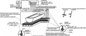
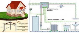
If it is planned to equip a swimming pool or sauna in a private country house (that is, objects associated with high humidity), the issue of a potential equalization system will definitely need to be considered. Its organization will make it possible to combine all large metal components of a given facility (including steel pipelines and metal doors) into a single chain. And that, in turn, is connected to a ready-made ground loop, as shown in the photo on the right.
Grounding principle
To make it clearer why grounding is needed in houses or in the country, we need to consider the principle of its operation, based on the fact that electric current always chooses the shortest distance for drainage. In other words, electronic carriers always flow into circuits that have minimal resistance. In an emergency situation, when the current-conducting body of the device becomes energized due to insulation damage, this is precisely what happens. If this has already happened, the only thing that can protect the user working with them is the presence of a chain to drain dangerous current.
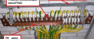
Its branching can be achieved by installing a special grounding circuit (GC), the individual elements of which are connected to the housing of the protected electrical equipment. Thanks to this, the emergency current that poses a threat to humans is reduced to a safe value. The latter is explained by the fact that most of it flows into the ground along a parallel chain formed by the ZK design (see photo below).
The principle of operation of the grounding system
Important! The magnitude of the current component flowing through the human body largely depends on the isolation of his legs from the ground.
If you wear rubber shoes or a thick protective mat, it decreases in absolute value, ideally approaching zero. With this in mind, professional electricians usually work on equipment while sitting on a rubber mat and wearing rubber boots.
Contour selection
Before calculating the circuit, you are given the opportunity to choose one of the following options for grounding devices:
- A triangular structure, the parameters of which are determined at the design stage.
- An extended linear structure mounted along the perimeter of the protected object.
- Modular pin grounding design.
Each of the above methods of assembly and subsequent installation of grounding devices requires detailed consideration.
Triangular design
This option for making a locking device is the most famous and widespread among professionals and amateurs. To arrange such a structure, you will need to prepare the following elements:
- Two-meter metal rods (reinforcing bars) in the amount of 3 pieces.
- The same number of steel jumpers designed to combine the rods into a single structure.
- A copper busbar required to connect the circuit breaker with the point of collection of conductors from the grounded equipment in the distribution cabinet (GZSh - main grounding busbar).
The plane of the welded contour with the pins already driven into the ground when arranging the charger should be located at a depth of approximately 30-60 cm.
Linear outline
Linear grounding is selected when it is necessary to connect several pieces of equipment located at a distance from one another to a protective structure. It consists of several pins (3) driven into the ground, the location of which relative to each other is selected from the calculated data.
Linear diagram of a ground loop for a private house
From the structure assembled according to this scheme, as in the case of a triangle, a branch (2) is made towards the distribution panel with the main shield. Before calculating such a circuit breaker, it should be taken into account that the total number of pins is limited by the mutual influence of emergency currents flowing in each single ground electrode.
Modular-pin grounding
The modular type of charger is used in situations where the area on the site in front of the house is limited in size and a single pin structure is allowed.
Installation diagram of a single grounding electrode
It contains the following elements in its kit:
- One and a half meter long steel rod with copper coating and available on
- working part threaded.
- A special coupling made of brass, providing a threaded connection of a vertically driven pin with a grounding tap.
- Brass clamps of a special design, guaranteeing reliable connection of the metal pins with the connecting strip.
- Tips for the ground rods themselves.
- An attachment with an impact platform that allows you to transmit impulse from a driving tool (vibratory hammer).
Modular-pin grounding kit
Please note: For reliable protection against corrosion, all threaded elements of the rods are coated with graphite paste, included in the original delivery set.
The protective lubricant lasts for a long time and does not spread when the pins and other elements of such a charger are heated. The anti-corrosion tape included in the composition is resistant to aggressive environments and protects the entire structure from destruction.
Read more about installing modular pin grounding on this page.
Grounding schemes, which one to choose
Before making grounding in your private home, you will need to familiarize yourself with the features of the arrangement and operation of protective systems that involve the use of one of the well-known schemes. To do this, you need to consider the following important points:
- When organizing the power supply of any modern facility, in addition to the neutral and phase buses, a so-called “grounding” conductor must be connected to it.
- Its main purpose is to protect people from dangerous potential that enters the body of devices when the insulation of conductors is broken.
- To do this, the grounding bus on the substation side is connected to a special grounding element (circuit), which is installed directly on its territory.
Additional information: Thanks to this, the protection function via the neutral core (combined with the working zero or via a separate conductor) is transferred to the consumer side.
At the same time, the grounding devices considered here in the house are usually classified as “repeated” chargers, duplicating station ones in case of a break in the neutral (combined PEN conductor).
According to the method of grounding the neutral core of the transformer at the substation and the facility on the consumer side, all used circuits are divided into the following two categories:
- Firstly, these are systems with a solidly grounded neutral, which are the most common method of grounding transformers whose secondary windings are connected by a star. In this case, their midpoint is permanently connected to the circuit.
- Secondly, circuits with the so-called “isolated” neutral are often used, in which the middle point is not connected to ground or is connected to it through the high resistance of the protection device.
a) a network with a solidly grounded neutral, b) a network with an isolated neutral connected to the ground through an arrester
Useful note: In the second case, the working windings of the transformer perform a separating function and are usually used for industrial purposes or in special electric heating installations.
Their use is associated with the need to isolate current-carrying parts of equipment from the ground loop. According to the rules of electrical installations, a solidly grounded neutral is usually designated as “TN”. One of the most common methods of protective use of such a neutral is to connect metal housings of devices to it via a separate bus.
Types of grounding systems (GS)
When studying the latest edition of the PUE, one immediately notices that Chapter 1.7 of the document provides the following list of protective circuits:
- TN-C or a system with combined working and neutral conductors (English “common” means “common”);
- TN-S or a circuit with separate routing of these buses (“select” or separate wiring);
- TN-CS is a method that is a combination of the 2 previous approaches;
- special schemes for connecting equipment to protective circuits with an isolated neutral, designated as TT and IT.
Basic grounding systems for electrical networks
The correct choice of a grounding system that is optimally suited for the specific operating conditions of equipment in a private home is another problem that requires an immediate solution.
Selecting a grounding system
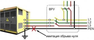
It is recommended to resolve this issue at the design stage of a suburban building, that is, long before the construction of the object itself begins. The parameters of the electrical wiring installed in the building (selection of a set of electrical installation products, in particular) depend on which system of protection against electric shock is chosen. In a situation where a cable with two working conductors runs down to the house from a high-voltage pole, this means that the TN-C type grounding system is used in the supply.
A cable with two working cores runs down to the house from a high-voltage pole
Please note: In this case, re-grounding is mandatory, since the working and grounding conductors are combined (PEN).
Artificially splitting it on the input-distribution panel strip will allow you to isolate a separate PE wire, which can already be used to organize a local grounding loop. This type of protective system is obsolete and is used only in older buildings.
Connecting the house to the ground loop using the TN CS and TN-S system
If a major renovation of a private house is planned with a complete replacement of electrical wiring, the TN-CS system is chosen as a temporary measure. It can be used until local power grid services upgrade them and install a five-core power cable (with a separate grounding bus) to the region. By the way, in this case (according to experts), organizing re-grounding on a personal plot will not hurt at all. When implementing this scheme, a common or combined wire PEN is used on part of the route from the substation to the consumer, and on the supply to the facility equipment it is divided into PE and N.
The most expensive in terms of associated costs, but the most convenient and reliable in operation, is the TN-CS circuit. This is a TN-S type system operating in conjunction with transformers with a solidly grounded neutral. In this case, the PE and N conductors are separated along the entire length of the power line from the transformer substation to the consumer. That is, they come to it as two independent buses: a zero working N and a zero protective PE wire. As already noted, to guarantee the security of the facility itself and the people working in it, the PE grounding wire can be connected to a circuit located near a private home. In this case, there are no particularly stringent requirements for the contract itself.
However, if you have this system, you will have to put up with its characteristic disadvantages, which are as follows:
- Electrical wiring throughout the house and outbuildings should be laid with a three-core wire.
- If you have a 3-phase power supply of 380 Volts, you will need a cable with 5 cores.
- In this case, the cost of components and materials increases significantly.
Important! On the other hand, when operating such a system, the safety of working with the equipment being serviced increases and the arrangement of re-grounding is simplified.
Modern power supply lines (both overhead and cable) are laid only using a five-core cable protected by the TN-S system.
TT system
TT grounding system
This system is most popular for grounding private houses, cottages and country houses.
The peculiarity of this method of protecting equipment and people working on it is its use only in situations where no other grounding system is suitable. In this case, the neutral core of the substation transformer does not have direct electrical contact with the grounding busbar, which in turn is connected to a separate grounding loop.
Important! That is, in this system, the neutral network wire (the so-called “neutral”) is not connected to the grounding circuit installed on the consumer side.
Specific situations when the choice of a TT system will be required are described in detail in the current regulations (PUE, paragraph 1.7.59, in particular).
Important! Since the drain current that occurs in an emergency situation may be insufficient to trigger the usual protection, according to paragraph 1.7.59, an RCD or an RCD is additionally installed in it.
Close to TT in design is the IT system, which can be examined in detail in the next section.
Connecting the house to the ground loop using the IT system
IT system
This method is used if the neutral of the substation transformer is completely isolated from the ground. Alternatively, it can be connected to it through a spark gap, the resistance of which is high at low voltages and decreases sharply when they increase above the limit level.
Additional information: This device reliably protects station electricity consumers from primary voltage entering the secondary part of the winding.
In such a connection circuit, the power network supplying power to electrical installations lacks not only the neutral wire N, but also the grounding bus PE. At the same time, they do not have single-phase voltage in the literal sense of the word. All consumers connected to such a line receive a linear voltage of 380 Volts, operating between phases A, B and C). Due to the fact that the short-circuit currents in this system, like the previous case, are not very large, the use of RCD devices or differential circuit breakers is considered mandatory.
To conclude this section, we note that in nature there are no grounding systems that would be universal and suitable for all occasions. Each of them has known pros and cons, nevertheless fulfilling the main task - creating the safest working conditions for service personnel and ordinary energy consumers. A competent approach to choosing the type of system protection is impossible without a clear understanding of what it is intended for and how it works in power lines.
Initial data for calculating grounding
Before starting the arrangement of grounding, the calculation of which needs to be carried out, it is necessary to decide in advance on such initial data as:
- Linear dimensions of steel pins driven into the ground.
- The distance between them (installation pitch).
- Permissible immersion depth.
- Characteristics of the soil at the grounding site.
Additional note: Before carrying out the calculation, you will also need to know the value of the soil resistance Ohm at the installation site.
When determining it, it is important to remember that it varies greatly from place to place and largely depends on the climate zone to which the region belongs. In addition to these data, you will have to take into account the configuration and material of the workpieces from which the finished structure is welded (either a regular steel corner or a wide copper strip).
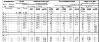
According to the PUE, the minimum dimensions of elements for a triangular or linear contour structure should be:
- strip - section 48 mm2;
- corner 4x4 mm;
- round bar – cross-section 10 mm2;
- steel pipe with a diameter of 2.5 cm with walls at least 3.5 mm thick.
Useful note: The minimum length of the pins is calculated taking into account the technical requirements (the need to obtain the required resistance to drainage into the ground).
In accordance with these requirements, it is chosen to be at least 2-2.5 meters. The distance between adjacent immersion points of the rods must be a multiple of their length. Depending on the size and configuration of the site for arranging the storage unit, the structural elements are installed either in a row or in the form of a regular triangle (sometimes a square shape is chosen for this). The methods used in this case for calculating various charger options aim to obtain data on the number of rods and the parameters of the connecting strip (its length and cross-section).
Issues covered in the PUE
Regulation of the operating procedure for various types of protective systems can be presented in the form of a certain set of requirements relating to the arrangement of individual structures.
According to them, the functional readiness of grounding loops, which include a whole set of structural elements, must be confirmed by the following technical data:
- Description of the design and composition of protective devices used in existing electrical installations;
- Formulas for calculating their sizes, as well as the resistance standards of grounding devices (GD);
- Tables with correction factors that allow you to introduce corrections for the quality and condition of the soil at the location of the contour (taking into account the material of individual elements);
- The procedure for organizing and conducting control tests available for grounding systems.
On a note. The presence of documented data on the performance characteristics and reliability of the functioning of the grounding loop of a private house, for example, will eliminate the possibility of electric shock to animals and residents.
When installing it, you are required to act in strict accordance with the PUE, as well as comply with all requirements regarding the operation of this protective device.
Calculation of grounding device elements
Determination of the parameters of the conductors used in the design of any ground electrode is carried out taking into account the following considerations:
- The length of the metal rods or pins greatly determines the effectiveness of the entire protective grounding system.
- The length of the elements of metallic bonds is also of great importance.
- The linear dimensions of these structural components determine the material consumption, as well as the total costs of arranging the charger.
- The resistance of vertically driven electrodes is primarily determined by the length.
- Their transverse dimensions do not have a significant impact on the quality and effectiveness of the protection provided.
Please note: The procedure for selecting the cross-section of conductors is determined in the PUE, since this indicator characterizes resistance to corrosion (electrodes should last 5-10 years).
In addition, you should always remember the “golden” rule, according to which the more metal blanks are provided in the circuit, the better the safety characteristics of the circuit.
Installation diagram of a single vertical ground electrode
It should also be taken into account that measures to organize grounding cannot be called an easy task. With a large number of system components, the volume of excavation work increases. And the decision on the specific method to improve the quality of grounding (due to the length or number of electrodes) remains up to the performer himself.
In any case, when arranging a memory of any type, it is recommended to adhere to the following rules:
- the rods must be driven in to a mark at least 50 centimeters below the soil freezing level;
- this arrangement will allow us to take into account seasonal factors and eliminate their influence on the performance of the protective system;
- the distance between the vertically driven elements depends on the shape of the chosen structure and the length of the rods themselves.
To correctly select this indicator, it is recommended to use reference tables.
Table for determining the parameters of grounding electrodes
In order to reduce the volume of upcoming calculations (simplify them), it is first desirable to determine the value of the resistance to the flow of short-circuit currents for a single rod.
Taking into account the influence exerted on the desired value by horizontal structural elements, the resistance for vertical pins is calculated using the following formula:
If the mounted charger is installed in heterogeneous soil (its other name is two-layer), the resistivity can be determined as follows:
where Ψ is the so-called “seasonal” coefficient;
ρ1 and ρ2 – resistivity of soil layers (upper and lower layers, respectively), taken into account in calculations in Ohms per meter;
H – thickness of the soil layer in meters located in the upper part of the earth cover;
t – depth of vertical pins or rods (it corresponds to the depth of the prepared trench), equal to 0.7 meters.
The number of rods sufficient to obtain effective grounding (horizontal components are not taken into account yet) is determined as follows:
where Rн is the spreading resistance standardized by PTEEP.
Taking into account the horizontal elements of the charger, the formula for determining the number of vertical pins takes the following form:
where ηв is understood as the coefficient of utilization of the structure, indicating the mutual influence of the drainage currents of various individual elements on each other.
Additional information: When arranging a system of linearly arranged pins, it should be remembered that in this case their mutual influence is especially strong.
As the installation step of these elements of the protective circuit decreases, its overall resistance to current flow increases noticeably. The number of elements of the grounding structure obtained from the results of the described calculations should be rounded to a larger value.
Online grounding calculations can be automated if you use a special online calculator developed for this on our resource.
DIY grounding device: step-by-step instructions
If you are asking the question: “how to make grounding at the dacha?”, then to complete this process you will need the following tool:
- a welding machine or inverter for welding rolled metal and bringing the circuit to the foundation of the building;
- an angle grinder (grinder) for cutting metal into specified pieces;
- wrenches for bolts with M12 or M14 nuts;
- bayonet and pick-up shovels for digging and burying trenches;
- a sledgehammer for driving electrodes into the ground;
- a hammer drill for breaking up rocks that may be encountered when digging trenches.
In order to correctly and in accordance with regulatory requirements perform a grounding loop in a private house, we will need the following materials:
- Corner 50x50x5 - 9 m (3 segments of 3 meters each).
- Strip steel 40x4 (metal thickness 4 mm and product width 40 mm) - 12 m in the case of one grounding point connected to the foundation of the building. If you want to make a grounding loop along the entire foundation, add the total perimeter of the building to the specified amount and also take a reserve for trimming.
- Bolt M12 (M14) with 2 washers and 2 nuts.
- Copper ground electrode. A grounding conductor of a 3-core cable or a PV-3 wire with a cross-section of 6–10 mm² can be used.
Once all the necessary materials and tools are available, you can proceed directly to the installation work, which is described in detail in the following chapters.
Selecting a location for installing the ground loop
In most cases, it is recommended to install the ground loop at a distance of 1 m from the foundation of the building in a place where it will be hidden from the human eye and which will be difficult to reach for both people and animals.
Such measures are necessary so that if the insulation in the electrical wiring is damaged, the potential will flow to the ground loop and a step voltage may arise, which can lead to electrical injury.
Excavation work
After a location has been chosen, markings have been made (for a triangle with sides of 3 m), and the location for the strip with bolts to be laid out on the foundation of the building has been determined, you can begin excavation work.
To do this, it is necessary to remove a 30–50 cm layer of earth around the perimeter of a marked triangle with sides of 3 m using a bayonet shovel. This is necessary in order to later weld the strip metal to the ground electrodes without any special difficulties.
It is also worth additionally digging a trench of the same depth to bring the strip to the building and bring it to the facade.
Hammering of grounding conductors
After preparing the trench, you can begin installing the ground loop electrodes. To do this, you must first sharpen the edges of a 50x50x5 corner or round steel with a diameter of 16 (18) mm² using a grinder.
Next, place them at the vertices of the resulting triangle and, using a sledgehammer, hammer them into the ground to a depth of 3 m
It is also important that the upper parts of the grounding conductors (electrodes) are at the level of the dug trench so that a strip can be welded to them
Welding work
After the electrodes are driven to the required depth using a 40x4 mm steel strip, it is necessary to weld the grounding conductors together and bring this strip to the foundation of the building where the grounding conductor of the house, cottage or cottage will be connected.
Where the strip will reach the foundation at a height of 0.3–1 moth of earth, it is necessary to weld an M12 (M14) bolt to which the grounding of the house will be connected in the future.
backfilling
After all welding work has been completed, the resulting trench can be backfilled. However, before this, it is recommended to fill the trench with saline solution in the proportion of 2-3 packs of salt per bucket of water.
Afterwards, the resulting soil must be compacted well.
Checking the ground loop
After completing all the installation work, the question arises: “how to check the grounding in a private house?” Of course, a regular multimeter will not be suitable for these purposes, since it has a very large error.
To perform this activity, the F4103-M1 devices, Fluke 1630, 1620 ER clamps, and so on are suitable.
However, these devices are very expensive, and if you do the grounding at your dacha with your own hands, then to check the circuit, an ordinary 150-200 W light bulb will be enough for you. For this test, you need to connect one terminal of the lamp socket to the phase wire (usually brown) and the second to the ground loop.
If the light bulb shines brightly, everything is fine and the grounding circuit is fully functioning, but if the light bulb shines dimly or does not emit a luminous flux at all, then the circuit is mounted incorrectly and you need to either check the welded joints or install additional electrodes (which happens when the electrical conductivity of the soil is low).
Example of grounding calculation
As a “classical” example of calculating grounding, let’s consider a charger option taking into account the given initial data, that is, we will carry out calculations for a single metal pin. Let us immediately make a reservation that such simple designs are used when organizing the re-grounding of high-voltage supports. In the situation under consideration, according to the provisions of the PUE (see clause 1.7.103.), the current flow resistance cannot be more than 15, 30 and 60 Ohms for voltages of 660, 380 and 220 Volts, respectively.
Calculation of a single grounding element for a 380 Volt overhead line support
According to the previously discussed method, first, using the table, select the type of vertical pin with the following characteristics:
- Material – steel.
- Shape: round rod with a diameter of 16 mm.
- Length L - 2.5 meters.
Please note: Semi-solid clay with a resistivity ρ equal to 60 Ohm per meter is selected as soil in accordance with the table.
The depth of the trench is taken to be half a meter. Then, from the same table, the correction factor entered for the average climatic zone is found. Its value for the actual length of the rods is up to 2.5 meters, taking into account soil freezing in the given area, is ψ = 1.45. The normalized resistance indicator for this type of charger is 30 Ohms. The next indicator, soil resistivity, is found by the formula:
ρ (in fact) = ψ•ρ = 1.45x60 = 87 Ohm•meter
The resulting calculated data looks like this:
- the penetration of a single pin into the ground is h = 0.5l + t = 0.5x2.5 + 0.5 = 1.75 meters;
- its resistance for our example (see formulas above) is no more than 30 Ohms, which corresponds to the requirements of the PUE for a given voltage.
When one grounding pin is not enough to support an overhead line, it is allowed to add one more or even several rods. In this case, a different technique will be required, used for a linear outline or a triangular design.
How to install a circuit yourself
To make your own ground loop, you will first need to select its type, and then carry out preparatory work based on this design. They include such mandatory procedures as choosing a location for the grounding circuit, selecting the necessary blanks, pins, jumpers, etc., as well as preparing a pit for the grounding loop.
Please note: As an example of manufacturing, we have chosen the simplest triangular design.
Let us consider the stages of the upcoming work in more detail.
Choosing a place for installation
When choosing a site in the local area suitable for arranging a protective contour, we proceed from the following considerations:
- it should not be located too far from the house; this will not only save on the connecting bus due to its short length, but also reduce the resistance of the current flow circuit;
- the soil at the site where the control panel is installed must be soft enough to allow metal pins to be driven into it;
- The quality of the soil on the site also affects the effectiveness of grounding (loams, plastic clay and peat have minimal resistance).
Important! If suitable soil layers are deep, the length of the corner pins will have to be increased to reach the desired soil layers.
We install the structure
First, a small pit about 40-50 cm deep is prepared, shaped like a triangle with dimensions slightly larger than each side of the future grounding structure. All subsequent actions are carried out in the following order:
- First of all, vertical grounding conductors are driven into the corners.
- Then their ends protruding from the ground, at a distance of approximately 30 cm from the ground surface, are connected to pre-prepared steel jumpers by welding.
- After this, a steel strip with a cross-section of at least 48 square meters is welded to one of the peaks (which is located closer to the house). mm and is brought as close as possible to the distribution panel.
- At the end of the strip, a steel bolt is welded to which a copper conductor with a cross-section of at least 16 square meters is screwed. mm.
- Its other end is inserted into the distribution panel and fixed in it to the main ground bus (GZSh).
Installation of a ground loop in the shape of a triangle
Installation of a linear grounding loop
At the final stage of work, the steel structure, ready for operation, is covered on top with previously discarded earth, which is then compacted well.
You can find detailed instructions for installing a ground loop in the article on our website.