Part 3
MARK ROMANOVICH NAYFELD
1959 STATE ENERGY PUBLISHING HOUSE, MOSCOW / LENINGRAD
The brochure provides basic concepts about the purpose of protective grounding in electrical installations of alternating current voltage up to 35 kV and their design. Brief information on the calculation and operation of grounding devices is provided. The brochure is intended for qualified electrical workers who have completed grades 7–10 of secondary school.
CONTENT
Part 1
1. Introduction
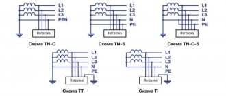
2. Protective grounding in a network with an isolated neutral
3. Grounding device
4. Step voltage. Touch tension. Potential equalization
5. Protective grounding in a network with a grounded neutral (grounding)
6. In what cases is grounding required?
Part 2
7. Resistance of grounding devices
8. Influence of the nature of the soil and its condition on the resistance to spreading of ground electrodes
9. Natural grounding and grounding loops
10. Grounding conductors
Part 3
11. Laying of grounding conductors, connections and connections
12. Example of calculation of a grounding device
13. Correct operation is the basis of safety
14. Measuring the resistance of grounding devices
Additional measures for grounding
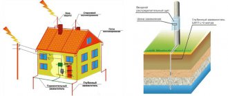
<How to further secure the grounding area? The area of the ground electrode and metal consumption can be reduced by constructing a special insulating fence, which is installed along the perimeter of the ground electrode. It should be noted that the fence must be made of dielectric. This approach makes it possible to prevent the spread of electric current over the earth's surface. In addition, the dielectric fence allows you to equalize the potential outside the ground electrode.
What is the best material to make a fence from?
To construct this structure, you can use any material that does not conduct electric current; it must also be very strong from a mechanical point of view, and its electrical strength must be at least 1 MV/m. For this purpose, insulators that are made on a bitumen basis are best suited. For example, these include brizol, produced from industrial waste. Its electrical strength is usually at least 20 MV/m.
LAYING GROUNDING CONDUCTORS, CONNECTIONS AND CONNECTIONS
Grounding conductors must ensure the safety of people, meanwhile, a violation of the continuity of the grounding circuit does not disrupt the normal operation of the installation and can remain unnoticed for a long period of time. Therefore, to ensure the reliability of the grounding wiring, the “Rules” require a number of measures to be taken:
1. To avoid breaking the grounding circuit or grounding, switches, circuit breakers or fuses should not be installed in it (except for cases when grounding conductors are disconnected along with the phase conductors).
For example, installing a switch or fuse in the zero-voltage circuit (Fig. 12) can lead to damage
| Rice. 12. Damage current when installing a switch or fuse in the neutral wire. | Rice. 13. Grounding the lamp body. |
when touching a zeroed body, even when the insulation is good. This will happen if the fuse box blows or the circuit breaker is tripped.
As shown in Fig. 13, in case of incorrect connection and possible break of the grounding conductor (marked in the figure), the consequences may be the same as in the case shown in Fig. 12, i.e. the lamp body will receive the same voltage through the lamp filament as the phase wire.
In a three-wire network with an isolated neutral, the grounding of the luminaires is carried out with a separate conductor (Fig. 14).
In Fig. 15 shows the inclusion of lamp sockets. In addition to cases of incorrect installation of the switch, there may be incorrect connections of the phase wire to the screw sleeve of the cartridge, which should not be allowed, since in many designs the sleeve is not sufficiently closed from accidental contact.
2. Zeroing of electrical receivers can be carried out in one of the following ways:
a) a separately laid copper or aluminum neutral conductor;
b) connecting to the neutral wire;
| Rice. 14. Grounding the lamp body in a three-wire network. | Rice. 15. Turning on the lamp sockets. |
c) by connecting to the grounding line with strip steel or using steel electrical wiring pipes, metal cable sheaths (if their conductivity is sufficient), etc.
Due to the possibility of a break in the neutral wire, which may result in electrical receivers remaining ungrounded, the Rules prescribe repeated grounding of the neutral wire.
Rice. 16. Connection of grounding conductors to the grounding line.
Repeated groundings are installed at inputs to buildings (outside or inside buildings) and overhead lines every kilometer.
A general view of the network with zeroing is shown in Fig. 17.
3. Grounding conductors must be protected from mechanical and chemical influences. Mechanical strength is ensured by the appropriate selection of sections, as well as protection at intersections in the ground with other communications (pipelines, cables, etc.). Protection against chemical influences can be provided by suitable coatings or painting. With this
Rice. 17. General view of the network with electrical equipment grounded.
The purpose is to lay grounding conductors at a certain distance from the walls (Fig. 18).
4. Grounding conductors, with the exception of steel pipes of hidden wiring, cable sheaths in the ground, etc., must be laid openly in the premises to allow inspection of the integrity of the wiring; it should not be allowed to lay them hidden in machine foundations, walls and
Rice. 18. Laying grounding bars along the wall.
other places where inspection is not possible. Passages through walls and ceilings must be made in sheet steel bushings or sections of steel pipes; grounding conductors must pass through them freely.
5. Exposed grounding conductors must be painted purple in order to facilitate their recognition by electrical personnel and to draw the attention of others to the special purpose of these wiring (neutral wires of overhead lines and electrical wiring are not painted).
6. Grounding wiring connections must provide reliable contact. The connection of grounding lines to grounding conductors should be carried out in two places. These connections, as well as connections of steel conductors in the ground, must be made by lap welding. The length of the overlap is taken to be equal to double the width for a rectangular section and 6 times the diameter for a round section (Fig. 19).
The bolted connections must be well cleaned and covered with petroleum jelly. In places where moisture may enter and in outdoor installations, the contacts should be coated with a lubricant to protect them from
Rice. 19. Connections and branches of grounding buses.
corrosion (the so-called “marine lubricant” LMS-1 of oil industry plants has proven itself well).
The connection of grounding conductors to equipment that is subject to frequent dismantling or to moving parts should be made with flexible conductors.
Places of connection to pipelines should be selected taking into account the possibility of their disconnection during repair work. Therefore, bypass connections should be provided for water meters, valves, etc.
7. Metal sheaths of cables (lead, aluminum) must have reliable connections along the entire length of the line to each other and to the housings of connecting, end and other couplings. At the ends of the lines, metal sheaths and cable couplings must be connected by flexible copper conductors and connected to the grounding line.
In table Figure 9 shows the cross-sections of these conductors recommended by the Research Institute of the Cable Industry for grounding metal lead or aluminum cable sheaths and cable box housings.
All connections of metal sheaths of cables and couplings (lead or copper) with grounding conductors are carried out by soldering; To ensure strength, soldered conductors must be additionally secured, for example, with wire bands. Connections to cast iron or steel protective housings of couplings, as well as connections to end couplings and funnels are made using bolts.
Table 9
what is it, an example of implementation for a private house
What is a grounding device?
The grounding device (earthing arrangtmtnt), according to GOST 30331.1-2013 [1], is a combination of a grounding conductor, grounding conductors and the main grounding bus. This term has the jargon of “ground loop”, which is incorrect.
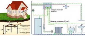
An example of implementation technology for the electrical installation of an individual residential building.
On one of the forums, I came across a standard project (hereinafter referred to as TP) series 5.407-155.94 , which was approved by the Department of Electric Power of the Ministry of Fuel and Energy of the Russian Federation and in which, directly, you can find the necessary information on the implementation of a grounding device for the electrical installation of a private house.
This project is not without shortcomings, for example, in terms of terminology, since it was released before the advent of the standards of the GOST R 50571 complex, but, nevertheless, in it we can find the implementation of the grounding device we need for an individual residential building.
The sketches of grounding circuits shown there were developed and used since the times of the USSR, which indicates sufficient time-testing in practice and, therefore, high reliability.
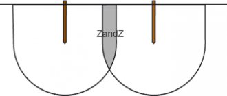
Next, we need to know the resistivity of the type of soil in which the ground electrodes will be located. For example, the soil type is clay sand. The calculated resistivity of clayey sand is ρ = 220 Ohm*m. Then, according to 5.407-155.94.1-57, we select a suitable sketch of the ground electrode (in our case, this is diagram N4). I slightly modified it to comply with the GOST R 50571.5.54–2013 standard and the result was the following:
Implementation of a grounding device (GZSh is not shown in the figure)
This grounding device, according to the technical specifications, is relevant for soil types with a design ρ ≤250 Ohm*m and must provide Rz ≤ 30 Ohm. And it consists of:
- 2 vertical grounding electrodes, 3 meters long and located at a distance L ≥ 6 m.
- one horizontal grounding electrode connected to a grounding conductor.
- The main grounding bus (GZSh), installed in the building (not shown in the sketch) and connected to the grounding conductor. The GZSh itself is connected with a protective conductor to the ASU protective bus, from which all protective conductors “begin”. The latter are connected to open conductive parts (OCP) of electrical equipment.
Some technical details:
- The grounding electrodes are deepened so that their upper part is 0.5 meters below the ground surface.
- The minimum dimensions of electrodes and grounding conductor laid in the ground can be found in table 54.1 of GOST R 50571.5.54–2013. For example, for a round vertical grounding electrode made in the form of a hot-dip galvanized steel rod, the minimum diameter will be 16 mm. And for a horizontal grounding electrode and a grounding conductor made in the form of a round wire made of the same steel, the minimum diameter will be 10 mm.
- The parts of the grounding system that are located in the ground, according to the technical specifications, should be connected to each other by electric welding with a double seam.
The length of the welding seam, in this case, is greater than or equal to 6 largest diameters with a round cross-section. That is, if we need to weld two electrodes with a diameter of 20 and 16 mm together, then the length of the weld should be at least 6 * 20 = 120 mm - The GZSh must have clamps for connecting protective conductors and protective potential equalization conductors. These terminals must allow the connection of conductors with a cross-section of ≥ 16 sq. mm. The GZSh must have one or two clamps for connecting grounding conductors with a diameter of ≥ 10 mm.
- The number of vertical electrodes depends on the soil resistivity and the maximum permissible resistance of the grounding device (GD). If the building's electrical installation has a TN-CS system grounding type, the resistance of the charger does not affect the protection against electric shock. Here it is necessary to ensure continuity of the electrical circuit PEN-conductor - protective conductor. Therefore, the resistance of the charger can be standardized, for example, by the requirements for protecting a house from lightning.
List of used literature
- GOST 30331.1-2013
- Standard design series 5.407-155.94
- GOST R 50571.5.54–2013
Sections of flexible copper grounding conductors of cable lines
| Cable core cross-section, mm2 | Cross-section of copper grounding conductor, mm2 |
| Up to 3x10 | 6 |
| 3×16 | 10 |
| 3×25 | 10 |
| 3×35 | 10 |
| 3×50 | 16 |
| 3×70 | 16 |
| 3×95 | 16 |
| 3×120 | 16 |
| 3×150 and above | 25 |
Grounding of wires with a metal sheath (SRG, TPRF, etc.) is also performed using flexible conductors by soldering. In this case, the grounding conductor is first wound on the wire in two or three turns for fastening.
8. Steel pipes used for grounding must have reliable connections. When the gasket is open, well-tightened red lead couplings with a lock nut on the side of the long thread section (squeeze) or other designs that provide reliable contact can be used. When laying hidden, only red lead couplings should be used, and they should additionally be welded on each side at one or two points.
If pipes are used for grounding, then even with open laying it is necessary to additionally weld the couplings to the pipes at one or two points.
9. Connections of neutral wires of overhead lines may be made using the same methods as phase ones (for example, compression).
Arrangement of protective current taps when working with three-phase electrical equipment
Switching three-phase electricity consumers differs from connecting conventional household electrical equipment, therefore the installation of protective systems is carried out in a different way. In this case, you should not confuse the neutral or ground wire involved in the control system, that is, involved in the start-up and stop circuit of the unit, with the protective conductor designed to divert a dangerous discharge to the ground.
Design, wiring, connection of electrical equipment
The work is carried out in several stages:
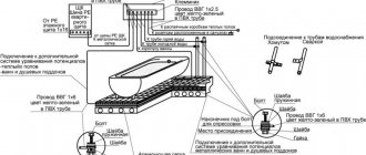
- A separate line (route) is installed along the perimeter of the room, made of a narrow metal strip 40x3 mm or copper wire with a cross-section of 16 mm2.
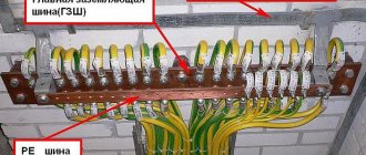
- A busbar (preferably copper) with contact devices (studs or holes for bolted connections) is mounted on it in a hidden place. It is possible to use a metal bus, but in this case welding the studs is a prerequisite.
- This line is connected to a grounding or grounding circuit, which is led out by a separate wire from the switchboard and has a reliable connection to the ground either directly or through a working zero
- The housings of all consumers (three-phase electric motors) are connected via a copper wire to the described bus.
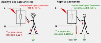
If a short circuit occurs from a voltage leak due to an insulation failure or a “breakthrough” of one of the phases onto the body of grounded electrical equipment, the current will immediately flow into the ground along the path of least resistance, that is, through the conductor connected to the working zero or ground. This will protect a person from electric shock when touching the body of the device.
A grounding device is allowed only if it is not possible to switch with the ground loop. In all other cases, only protective grounding is considered correct.
The unit is connected through a copper wire to a bus mounted from the grounding path
Mandatory use of additional protective devices
The described grounding and neutralizing systems are effective when significant leaks or short circuits occur on the housing of electrical appliances. However, to achieve complete safety when servicing equipment, it is necessary to use additional means of protection to ensure that the electrical circuit is broken when malfunctions occur.
At manufacturing enterprises, these can be automation units (insulation monitoring of BKI or maximum current protection). But the most common means, both in production and in everyday life, are circuit breakers and residual current devices, which:
- will ensure that the electrical circuit is de-energized in case of problems;
- protect the user from electric shock;
- will protect equipment from fire.
Such devices can be designed for single-phase or three-phase systems. They are:
- single-pole - installed on one of the lines (zero, phase);
- bipolar - installed on both wires of the electrical wiring;
- multi-pole (three or more) – used for three-phase voltage.
Household wiring diagram with PE grounding conductor and VA and RCD protection
The circuit breaker switches off when the current load exceeds the rated value indicated on the device body. The RCD monitors the state of the electrical network and is triggered when the slightest current leakage occurs.
EXAMPLE OF CALCULATION OF GROUNDING DEVICE
Consider the following example of calculating a grounding device. The substation grounding device must be made with resistance Rк
=4
ohm
.
The soil in the substation area has a measured resistivity ρ = 0.6·104 ohm·cm
.
The ground electrode is made of 50×50 mm
2.5
m
mm
steel strips .
It is necessary to determine the number of corners and the length of the steel strip.
First, we determine approximately the number of corners and the total length of the steel strip.
According to the table 3 corner 50×50 mm
has resistance to spreading
0.00318 ρ = 0.00318 0.6 104 = 19.1 ohm
.
According to inquiries made (at the meteorological station), the area belongs to climatic zone II according to table. 4. In accordance with this table, to take into account drying or freezing of the soil, we take the increasing factor for the corners to be equal to 1.8. Then the resistance of one corner will be equal
19,1·1,8 = 34,4 ohm
.
We will accept the location of the corners near the substation in one row with a distance between them of 3 m
(see Fig. 11), i.e. the ground loop will be relatively simple.
To take into account the mutual shielding of corners in the circuit, we take the utilization factor (see § 9) equal to 2 (The choice of utilization factors is given in specialized literature and electrical reference books). Thus, the resistance of one corner in the circuit should be taken equal to
34,4·2 = 68,8 ohm
,
and the number of corners
Thus, it would be possible to accept 17 corners for the circuit, if we do not also take into account the resistance to spreading of the strip as a grounding conductor. However, with a length of about 48 m
, which is required to connect 17 corners, taking into account this resistance, as we will see, will make it possible to reduce their number.
According to the graph in Fig. 10 we find that the resistance of a strip 48 m
is approximately 2
ohms
. According to the table 4 we accept an increasing factor of 4 for drying or freezing of the soil; the coefficient taking into account the mutual shielding of the strip with the pipes is taken equal to 2.5. Thus, the strip resistance should be considered equal to
2·4·2,5 = 20 ohm
.
The corners and strip represent two resistances connected in parallel. Their total resistance, i.e. the resistance of the substation grounding circuit Rк
; determined from the equation
where Rуг
- total resistance of all corners;
Rп
— strip resistance.
From this equation we find that the total resistance of the corners should be equal to
Now we specify the required number of corners. It is equal
To keep the connecting strip length at 48 m
, we extend it at two corners of the contour by 4.5
m
on each side.
The actual resistance of the grounding device must be verified by on-site measurements. If necessary, additional grounding conductors are connected to the circuit.
The above calculation was made based on the fact that there are no natural grounding systems nearby ( Rest
).
If they are present, it is necessary to measure their resistance. If their resistance is low enough (4 ohms
or lower for this example), then artificial grounding devices are not required. If it is too large, then it is reduced by adding artificial grounding conductors.
Let’s assume that in the case discussed above, you can use a nearby natural ground electrode (water supply) with a resistance of 5 ohms
.
In this case, the artificial ground electrode should no longer be made at 4 ohms
, but only at 20
ohms
. Its resistance is calculated by the formula
Further calculations are made in the same way as indicated above.
Installation of horizontal grounding
Horizontal grounding conductors should be laid at a depth of 0.5 m. If the land is arable, then it is best to increase the depth to 1 m. As a rule, such grounding conductors are installed using special devices.
In the case of a horizontal ground electrode located too close to the surface of the earth, the spread of electric current through the soil will not be uniform, but at a greater depth this effect is achieved without unnecessary costs and effort.
Conductors laid horizontally have significantly higher resistance compared to a similar electrode installed in a vertical position. It is for this reason that vertical electrodes are most often used when carrying out electrical installation work.
It is best to use deep vertical electrodes for this purpose, since they are able to reach layers of soil that conduct electricity well.
CORRECT OPERATION IS THE BASIS OF SAFETY
The practice of operating equipment shows that the vast majority of accidents occur due to non-compliance with the rules of the device, operating rules and safety regulations.
The correctness of the grounding arrangement must be carefully checked when they are accepted into operation after completion of installation work. The necessary tests must be carried out to determine compliance of groundings with the Rules and design data. The cross-sections, integrity and strength of grounding conductors, all connections and connections are checked.
When accepting grounding devices for operation, the following must be presented: a) as-built drawings and diagrams of the device; b) acts for underground work; c) test reports" ["Rules for the technical operation of electrical stations and networks" (PTE), 1953, § 858].
During the operation of the installations, the following inspection and testing periods for grounding devices must be observed.
Inspection of the outer part of the grounding wiring, checking the reliability of connecting equipment to it and the condition of breakdown fuses must be carried out simultaneously with routine and major repairs of equipment (PTE, § 859).
Breakdown fuses are installed on the secondary winding of transformers with an isolated neutral and a secondary voltage of up to 500 V
.
If the windings are damaged and high voltage reaches the low voltage winding, the insulating gap of the fuse is broken through and the latter is connected to the ground through the installation's grounding network.
Measurements of the resistance of grounding devices at power plants, substations and high-voltage power lines with selective opening of individual elements of the grounding device must be carried out at least once every 5 years. The measurement results must be documented in a report (PTE, § 860).
When using artificial soil treatment to reduce the resistance of grounding conductors with salt or other substances, this period should be reduced to approximately 2 years.
PTE of electrical installations of industrial enterprises (edition 1951) require for factory installations to measure the resistance of grounding devices and check the outer parts of the grounding wiring at least once a year (for overhead lines once every 5 years), and the condition of breakdown fuses - monthly .
For each individual grounding device, a passport must be drawn up containing a diagram of the device, basic technical and design data, data on the results of inspections and tests, information on repairs made and changes made (PTE, § 861).
Before starting repair work in electrical installations, temporary portable grounding has to be performed in a number of places. Grounding conductors must be connected to these places, and places for connecting portable grounding and short-circuiting conductors must be cleaned and greased with petroleum jelly.
The imposition of temporary grounding must be carried out in compliance with the requirements of the PTE. Portable grounding conductors must be made of copper, resistant to heat during short circuits and have a cross-section of at least 25 mm2
. The tips should be brazed or welded on.
In the operation of electrical installations, it is necessary, first of all, to strive to prevent faults to ground and frame. This can be achieved mainly through careful and timely monitoring of the network and equipment insulation status. Insulation violations must be corrected as soon as possible.
Electrical injury statistics show that a large number of accidents occur when using portable electrical equipment. Therefore, special attention should be paid to its correct operation.
Portable electrical equipment includes: power tools (electric drills, electric hammers, etc.) and electrical devices for industrial purposes, household appliances of all kinds, children's toys, lamps and similar electrical receivers connected to a current source with a flexible wire through a plug socket.
In portable electrical receivers, short circuits to the housing are more frequent than in stationary installations. Damage to the insulation of these receivers and flexible conductors occurs quite often due to constant movement. Hand-held devices with metal handles, such as power tools, are also dangerous because they are covered with hands while working, and if voltage accidentally appears on their bodies, the worker may experience a cramp, preventing him from unclenching his hands and releasing the current without outside help.
A large number of cases of electrical injuries when using portable equipment is explained not only by its widespread use in industry and everyday life, but mainly by direct violations of safety regulations, defects in the design of the equipment itself and flexible connections, and, finally, the use of all sorts of outdated and homemade devices.
In conditions of industrial premises or outdoor work, where there is usually an increased danger, the housings of portable equipment, in accordance with the requirements of the Rules, must be grounded, with the exception of equipment operating at voltages of 36 and 12 V
.
According to the “Rules,” the grounding conductor must be in a common shell with the phase conductors and have an equal cross-section (at least 1.5 mm2
), and flexible conductors must be used. Thus, separately laid grounding conductors are not allowed, as there is a danger of their breakage.
With well-organized operation, the condition of the equipment and flexible connections should be checked quite frequently, in particular after repairs. For power tools, generally speaking, a check should be done before each use.
Incorrect connection of power tool grounding conductors (Fig. 20) has repeatedly caused accidents. Their unreliable connection (by hanging without fastening) or combining the grounding conductor with the neutral wire should therefore not be allowed.
Rice. 20. Grounding of portable power tools.
Portable lamps must be used in accordance with safety requirements and have no live parts accessible to touch. Such lamps are not grounded.
Sockets and plugs for portable electrical receivers in industrial environments must have special contacts for connecting a grounding conductor (Fig. 21). The design of such a plug
Rice. 21. Grounding pin plug.
connection eliminates the possibility of using current-carrying contacts as contacts intended for grounding. The connection between the grounding contacts of the plug and the socket is established before the current-carrying contacts come into contact; the shutdown order is reversed. For this purpose, the grounding contact is longer than the current-carrying contacts. The grounded contact of the socket outlet must be electrically connected to its body, if the latter is made of metal.
In residential buildings and public buildings where the floors are made of wood and other materials that provide good insulation, grounding of portable electrical equipment is not required.
WTF are ground loops? | Hackaday
These magical creatures appear out of nowhere and fry your electronics or irritate your ears. Understanding them will undoubtedly save you money and stress. In short, a ground loop is what happens when two separate devices (A and B) are separately connected to ground and then also connected to each other through some kind of ground connection cable, creating a loop. This provides two separate paths to ground (B can go through its own connection to ground, or it can go through the cable ground to A and then to A's ground), and means that current can start to flow in unexpected ways. This is especially noticeable in analog audio-visual installations , where the result is a humming sound or visible streaks in the picture, but is also sometimes the cause of unexplained hardware failures.
Can you find the loop?
One example is cable television. This is an analog signal that enters your home and is grounded at one location, usually outside your home. The cable snakes its way to your entertainment center, where it connects to the receiver, which is grounded elsewhere. This creates a loop and, thanks to electromagnetic induction associated with all sorts of AC signals around, a stray current that then flows through various circuits. Another way to think of it is as half a transformer; This is a single circuit, and a significant part of this circuit is immediately downstream from the live wire of the building's electrical network with a constantly changing current.
It is not uncommon for audio equipment to experience hum at 50 or 60 Hz due to the influence of ground loops.
Solution
Now that you're an expert, fixing the problem (or avoiding it entirely) is quite simple. The safest way is to cut the loop, which means removing the cable or replacing it with something other than wire. You can switch to a wireless connection such as Bluetooth or WiFi. Some wired protocols use differential signals instead of single-ended signaling, so there is no need for a common reference ground. Rearrange the plugs so they fit into the same socket, making the loop as small as possible. Another option is to use an isolator, which you can purchase for your chosen cable or design into your project with an opto-isolator or isolation transformer. Do not use a power plug or remove the ground pin as this simply eliminates the safety feature and may create a dangerous situation with the chassis under voltage .
When it comes to your oscilloscope, it's likely that at some point you'll want to test something that's mains powered, and then you'll end up with a completely different type of ground loop. If your item is battery powered, there is no danger here; go crazy because there is no way to create a ground loop. If it's connected to the wall, but through an isolated power supply (something with only two pins and an isolation transformer), it's fine because there's still no path for the ground loop, but you might see some noise from the dirty power supply.
But if it's plugged in and has a ground pin (even indirectly, like a device powered by USB through a computer's power supply), there's the possibility of creating a ground loop because you're connecting a grounded scope to another grounded device via a probe. The ground clamp on the probe connects directly to the ground pin, and the grounds on all the probes connect to each other, and those ground pins connect to the ground on your device.
If it wasn't clear, it's better to phrase it this way: "all of your grounds are already connected to each other and connected to the same wire - the ground pin." When you connect a ground clamp to the device under test, you create a ground loop that will add noise to your measurements and may damage the oscilloscope.
The oscilloscope probe ground is connected. Technically, you only need to attach one ground clamp to the test device. The probe ground is connected directly to ground. They don't swim.
If you make the mistake of attaching a ground clamp to something that is not actually grounded, you will have all sorts of problems since the device is now shorted to ground through your probe, which will quickly self-destruct. Testing devices with a ground pin requires special care to prevent connecting devices with different potentials. It is possible to break the ground loop by simply not connecting the ground clamp, although this has other consequences.
Here, it is best to use differential probes or connect the device under test to an isolation transformer. Don't, and don't, remove the ground from your scope because you'll be touching it a lot and it's best not to get electrocuted.
So, to summarize: land is not just land. For noise measurements, it is best that each device has one and only one path to one ground point. When there are two or more paths to ground, they can form a loop that picks up all kinds of electrical and magnetic interference from the environment. Fixing a ground loop is as simple as breaking it, but to do this you must have a good mental picture of all the ground paths in the game. What's the most complex ground loop you've ever seen? Are there not enough good solutions?
MEASUREMENT OF RESISTANCE OF GROUNDING DEVICES
There are a number of ways to measure the resistance of grounding devices. Below is a description of the measurement principle using one of the instruments widely used in practice - a grounding meter type MS-07 (MS-08).
The device operates on the principle of a magnetoelectric ratiometer. The main parts of the device are two
Fig. 22. Schematic diagram of a grounding meter. I1, E1, I2, E2
— designations of the device terminals.
frames, one of which 1-1 is switched on as an ammeter, the second - 2-2 - as a voltmeter. These coils act on the axis of the device in opposite directions. Thanks to this device, the deflection of the instrument needle is proportional to the resistance (the value of U/I
), and the instrument scale is graduated in
ohms
.
The power source for measurements is a direct current generator G
, driven by hand.
P
and a rectifier
Bn
are mounted on a common axis with the generator. To measure the resistance of individual grounding electrodes or complex grounding devices, two more special grounding electrodes are required - probe Z
and auxiliary grounding
conductor B.
The auxiliary ground electrode creates a circuit for the measuring current through this ground electrode and the one being tested.
The measuring circuit runs from the plus terminal of the generator through the 1-1 frame, the auxiliary earth electrode, the earth electrode under test, the breaker and the generator. Frame 1-1 receives direct current from the generator, then breaker P
converts the current into alternating current, which enters the ground through the auxiliary ground
electrode
B. rectified through the rectifier Bn
. Thus, due to the presence of a breaker and a rectifier, direct current flows through the frames of the ratiometer (solid lines), and alternating current flows through the ground (dashed lines). The presence of a rectifier also prevents stray currents from entering frame 2-2.
To reduce the error, an additional resistance equal to 150,000 ohms
.
The distance between the tested grounding conductor and the probe must be at least: for single grounding conductors - 20 m
, for grounding electrodes made of several (two to five) pipes - 40
m
, for complex grounding devices - at least 5 times the value of the largest diagonal (
D
) of the area occupied by the grounding electrode being tested.
The distance between the auxiliary and the tested grounding should be taken at least 40 m
for simple grounding and at least 5
D
+ 40 for complex ones.
Reducing the specified distances leads to an increase in the measurement error. Measurements are made 2-3 times and the average value is determined.
What is grounding and why is it needed?
Grounding refers to a metal structure designed to reduce the voltage level to parameters that are not dangerous to humans. The most important installation feature is to install the system in places that ensure reliable insulation of the neutral wire.
In addition, the presence of grounding can significantly increase the emergency current. The need to increase this parameter is due to the fact that with increased resistance of the grounding loop, despite the critical state of electrical appliances, the circuit current in some cases is not enough to trigger the protective mechanisms, while the risk of electrical injury remains.
Fundamentally, the grounding loop is a system of several conductors that ensure the connection of current-carrying elements of equipment with the ground. Based on their purpose, these systems can be divided into three main types:
- The working type is designed to ensure the operability of the equipment, both under normal conditions and in unforeseen situations;
- The protective type provides protection for operating personnel in the event of a breakdown of current-carrying elements on the housing;
- The lightning protection type ensures that atmospheric electrical discharges are discharged into the ground.
In addition, a distinction is made between artificial and natural grounding and grounding. The difference is that the artificial one is a specially made metal frame. Natural structures include metal structures made for other purposes and used as grounding.