The absence of grounding of electrical equipment or its incorrect implementation can lead to industrial injuries, failure of automation devices or their incorrect operation, and errors in the readings of measuring equipment.
This occurs as a result of an insulation breakdown between live parts and the equipment housing. As a result, voltage appears on the housing and electric current flows, which can cause injury to a person and lead to malfunctions of electrical devices. To avoid this, the part of the installation that is not normally energized is connected to a grounding device. This process is called grounding.
Classification of grounding devices
The grounding system for electrical installations is a complex consisting of a grounding loop and conductors connecting it to equipment housings to ensure that excess current resulting from phase contact with the housing flows into the ground. The current classification of grounding devices in Russia (hereinafter referred to as GD) implies gradation according to the following criteria:
- Looks like neutral. According to the presence of a connection with a grounding device: grounded;
- isolated.
The organization of the grounding system is regulated by the rules of electrical installations (PUE). The document regulates the procedure and characteristics of the classification of grounding systems. Letters of the English alphabet are used to indicate markings:
T – grounding;
N – neutral;
I – isolated;
C – general;
S – separate.
This type of marking allows you to determine the current generator protection method used and the preferred grounding schemes for electrical installations on the consumer side.
When installing power supply lines, three grounding systems are considered generally accepted in Russia:
- TN-C - means that the neutral working and protective conductors are combined into a common bus along the entire route.
- TN-S – neutral working and protective conductors are laid separately.
- TN-CS - neutral working and protective conductors are combined on part of the route, and laid separately on the rest.
The following systems are less common:
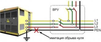
- TT – neutral working and protective conductors are grounded separately. Most often, this method is used in case of unsatisfactory condition of the supply overhead power lines or to prevent injury to people through the conductive surfaces of temporary structures.
- IT - in this scheme, the neutral is isolated from the ground or grounded through special equipment. This option is most often used if it is necessary to ensure a high level of equipment protection. Since with this connection option the risk of sparking is minimal.
Standards Standards for the design of grounding networks
R.N. KARYAKIN
Doctor of Engineering sciences, professor
STANDARDS FOR CONSTRUCTION OF GROUNDING NETWORKS
MOSCOW
Energoservice
2002
Doctor of Technical Sciences, Professor K aryakin Rudolf Nikolaevich
The standards apply to grounding devices of electrical installations with voltages up to 1 kV and higher. This 3rd edition of the Standards, being a technological addition to Chapter 1.
7 “Grounding and protective measures for electrical safety” of the Electrical Installation Rules (PUE), meets the requirements of the standards of the International Electrotechnical Commission (IEC): 60364-5-54-2001: Earthing arrangements protective conductors and eq u ipotential bonding and 61024-1-2001: Protection of structures against fire, explosion and life hazards (Lightning Protection).
Compared to the previous 2nd edition, the volume of the book has been more than doubled due to the addition of new regulatory materials.
The book is addressed to engineers (electrical engineers, electric power engineers, electrical installers, builders), foremen, foremen, technicians, electrical workers involved in the design, installation, testing, certification, energy supervision, repair, reconstruction and operation of electrical installations.
PREFACE TO THE 3RD EDITION
This 3rd edition of the Standards for the Construction of Grounding Networks is intended as a technological
continuation of Chapter 1.7 “Grounding and protective electrical safety measures” of the Electrical Installation Rules (PUE).
That is why the Standards require their practical application simultaneously
with PUE in a single process of creating electrical installations and lightning protection of buildings and structures: design - ordering equipment and materials - installation - commissioning and acceptance tests - certification.
Compared to the previous 2nd edition, the volume of the book has been more than doubled by adding additional regulatory requirements for grounding and lightning protection networks, taking into account new standards of the International Electrotechnical Commission (IEC): 60364-5-54-2001: Earthing arrangements protective conductors and equipotential bonding and 61024-1-2001: Protection of structures against fire, explosion and life hazards (Lightning Protection).
The author expresses gratitude to Eng. A.S. E rmolenko for his great help in preparing the 3rd edition of the manuscript for publication.
Author
Moscow
October 29, 2001
FROM THE PREFACE TO THE 1ST EDITION
In contrast to the well-known instructional materials on the construction of grounding networks and lightning protection, the proposed Standards comply with the Basic Rule for the Construction of Electrical Installations
(see Chapter 1, clause 1.1.) and the set of standards GOST R 505 71 (M EK 364), according to which grounding or grounding of open conductive parts of electrical installations should be carried out:
1) at a rated voltage of more than 50 V AC or more than 12 0 V DC - in all electrical installations;
Technical requirements for the organization of grounding of electrical installations
Ultrasound is used to protect people and equipment from the destructive effects of electric current. Safety is ensured by connecting the protected enclosures of electrical installations to the ground. Work on organizing grounding networks is regulated by the provisions of GOST 12.1.030-81, according to which protective grounding of an electrical installation should be carried out under the following parameters:
- at rated voltage values of 380 V or more alternating current and more than 440 V or more direct current - at any values;
- at rated voltage values of 42-380 V AC 110-440 V. For work associated with increased danger.
A properly organized grounding system for electrical installations can neutralize excess potential of any power and protect people, equipment and buildings from the effects of electric current, whether surges caused by turning on or off power equipment or lightning.
The operating principle is based on the difference in resistance of the human body and ultrasound. Excess potential is diverted in the direction of a lower indicator, i.e. towards the protective circuit.
Selection of natural ground electrodes
According to the rules for the construction of electrical installations, their housings must be connected to artificial or natural grounding conductors. The following metal objects are used as natural ones:
- frames of underground metal structures having direct contact with the ground;
- protective covers for cables laid underground;
- metal pipes, with the exception of gas and oil pipelines;
- railway rails.
Contact of the object with the natural ground electrode must be made in at least two places. The advantages of this method are simplicity, efficiency and cost reduction in organizing an electrical safety system.
The following objects cannot be selected as natural grounding conductors:
- pipelines of flammable and explosive gases and liquids;
- pipes coated with anti-corrosion insulation;
- sewer pipelines;
- central heating pipes.
Current flow resistance
Grounding works according to the following principle: the current flowing into the ground through the fault point first passes to the body of the electrical installation and from it through the ultrasound into the ground. Obviously, when organizing grounding networks up to 1000 Volts, it is important to create a chain that ensures excess charge flows into the ground.
Grounding resistance values for networks for various purposes:
| Purpose of the network | Maximum resistance value, Ohm |
| Private houses 220, 380 Volt | 30 |
| Industrial equipment | 4 |
| Current source at voltages of 660, 380 and 220 Volts | 2, 4, 8 |
| Private house when connecting a gas pipeline | 10 |
| Communication line protection devices | 2 (less often 4) |
| Telecommunications equipment | 2 or 4 |
To obtain the resistance indicators established by the standards, standard procedures should be followed:
- Increase the area of contact between the parts of the grounding device and the ground.
- Ensure high-quality contact between the device elements and the connecting busbars.
- Strengthen soil conductivity by moistening or increasing its salinity.
To monitor compliance of resistance with prescribed standards, its level should be checked at least once every six years.
Ultrasound operation in case of violation of protective insulation of electrical equipment
Violation of the integrity of the protective insulation often leads to a phase short circuit to the housing. Further developments depend on the quality of the electrical safety system. The following options are possible:
- There is no grounding, the residual current device is not installed. The most unfavorable situation. When you touch the body, a strong blow is felt.
- The housing is connected to the grounding system, there is no RCD. If the leakage current is high, the machine will operate and turn off the supply line or circuit. This option can lead to the accumulation of excess potential on the case if the resistance of the junctions and the fuse rating are high. This situation is dangerous for people.
- There is no grounding, the residual current device is installed. The leakage current will trigger the RCD and the person will only have time to feel a weak electric shock.
- The housing is connected to grounding, an RCD is installed - the most reliable option, ensuring the protection of people and equipment due to the fact that the protective devices complement and partially duplicate each other. When a phase is short-circuited to the housing, the excess potential drains through the grounding system. At the same time, the residual current device reacts to the leak and turns off the current supply, eliminating the possibility of electric shock to people. If the leakage current significantly exceeds the capabilities of the RCD, the machine may trip and duplicate its function.
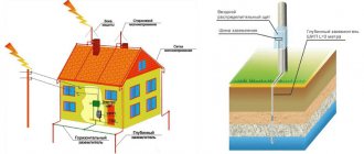
Artificial and natural grounding electrodes
We have understood the terms, now we can consider which conductors can be used as a grounding conductor. From the title of the section it becomes clear that they can be either natural or artificial.
Natural ones include metal systems of underground pipelines (water supply, sewerage, wells) or metal structures of buildings and structures that go deep into the ground.
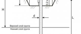
As for artificial grounding conductors, metal profiles are most often used for this, which are driven into the ground to a depth of 2.5 to 3 m. Most often, steel corners with a shelf width of 50 mm, fittings or pipes are used for these purposes. A prerequisite is to leave 10 cm of protruding profile above the ground surface. There should be either four or three grounding electrodes; they are installed either in a square or in a triangle. The protruding ends are tied with round reinforcement with a diameter of 10-16 mm or a steel strip 30 mm wide. All joints are made only by electric welding.
Grounding of workshop equipment
According to the rules for installing electrical installations up to 1000 Volts, they are classified according to the type of grounded devices:
- For standard machine tools.
- For electric motors and welding machines.
- For mobile installations and operating electrical appliances.
Grounding of typical machine equipment
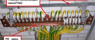
To ground workshop equipment, use the circuit of the potential equalization system (hereinafter referred to as EPS).
A potential equalization system is an element of a grounding device, which is a circuit of conductive elements for connecting equipment housings in order to achieve potential equality.
It is important to pay attention to the following technical issues:
- Determine the location of the EMS circuit in the work area.
- Calculate the thickness of the bus used to connect the machine body to the ultrasonic unit.
- Determine the location of the stationary grounding.
- Find out what devices are used to protect dangerous parts of equipment.
Monitoring these issues is the responsibility of a shop electrician who has information about the structure and location of the elements of the grounding system and the procedure for connecting machine bodies to it, including the location of the grounding bus connection point prescribed by the machine design.
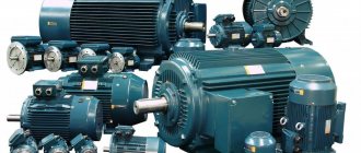
Grounding of electric motors
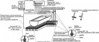
According to the standards, grounding of electric motors is also mandatory, except when the equipment is installed on a metal pedestal that has contact with the ground. In other cases, it is necessary to connect the housing to the grounding system using a copper conductor. The rules indicate that contact with grounding must be direct for each electric motor and sequential connection of several devices through a grounding chain is unacceptable, since a broken line leads to loss of contact for all electric motors at once.
To properly connect the grounding, it is necessary to provide an additional bus on the 380 Volt power supply cable, one end connected to the grounding terminal in the engine distribution box, and the other to the power cabinet housing. In this case, it is important to follow the connection sequence and first connect the electrical panel to the grounding system. It is also important to ensure that the cross-sectional diameter of the conductors complies with established standards.
Grounding of welding machines
The rules for electrical installations also regulate the procedure for grounding welding machines. In this case, grounding of equipment housings is mandatory. In addition to the housing, the transformer secondary winding must also be grounded through one of the terminals. The other is used to connect the electrode holder.
Near the grounded terminal on the housing there is a corresponding sign and a device for fixing the busbar connecting it to the protective circuit. The transition resistance of the protective circuit or device should not be higher than 10 ohms.
To increase the electrical conductivity of the grounding system, the contact area of the connections should be increased, including the area in contact with the ground. The connection to the charger must be individual for each welding machine and should not be made through a grounding circuit, since in the event of a break, contact with the charger will be lost by all devices at once.
Protection of mobile installations
Particular attention should be paid to grounding mobile installations. To protect mobile installations, grounding electrodes for mobile installations GOST 16556-02016 are used. Since the peculiarities of their operation make it difficult to meet the requirements for ensuring contact resistance indicators, therefore, the rules for the design of electrical installations allow an increase in the indicator to 25 Ohms. This only applies to self-powered units with an isolated neutral.
This type of ultrasound can be used for installations with reduced sparking, which are not power sources for other equipment, as well as for mobile units that have their own grounding switches that are not currently in use.
Mobile units equipped with autonomous power supply require regular inspection for damage to the protective shell, since they have an isolated neutral and an increased risk of the formation of rubbing joints.
Protection of electrical appliances
When working with electrical appliances of various types, you can rely on standard safety rules:
- Protect exposed live parts.
- Increase protective insulation.
- Use special devices to restrict access to equipment housings.
- If the design allows, you can use a voltage drop as a measure.
To avoid insulation breakdowns and phase contact with the body of an electrical device, traditional methods are effective:
- Availability of a grounding system.
- Potential equalization system.
- Strengthening the insulation of live parts.
- In some cases, as a safety measure when working with electrical equipment, you can use restriction of access to premises that pose a potential danger due to high humidity, dust, etc.
It is important to consider that if, in addition to grounding, other methods of protecting people are used, they should not be mutually exclusive and reduce each other’s effectiveness.
It is possible to use natural grounding conductors to provide protection only if there is no likelihood of damage to underground structures in the event of emergency current flowing through them.
Grounding installation location when working on an electric motor
It is equally important to install portable grounding switches on the electric motor when performing repair or maintenance work. They are mounted on stationary and mobile equipment.
In this case, service personnel are obliged to:
- Install grounding conductors if work is performed on an electric drive or equipment driven by it, where voltage may occur. Maintenance personnel are required to disconnect it from the power supply. Ensure protection against repeated or erroneous switching on, observing the rules of technical measures. And for two-speed engines, both winding circuits are turned off and disassembled.
- When the power is turned off, it is allowed to install a portable grounding electrode anywhere, a supply cable from the switchgear, a control panel, or an assembly. This must be a visible ground.
- Before starting work on equipment capable of rotating due to connected mechanisms (fans, smoke exhausters, pumps, etc.), shut-off valves (valves, dampers, etc.), the mechanisms are locked. Or measures are taken to mechanically fix them, and the rotors of electric motors are braked or couplings, for example, of conveyors are disconnected.
- Appropriate signs are posted and personnel are required to use personal protective measures.
The photo below shows portable grounding electrodes:
In the absence of a standard device, it is allowed to use wires as a portable grounding conductor, the cross-section of which should not be smaller than the supply cable.
Organizations carrying out repair work have detailed safety instructions, which detail the stages of workplace preparation and repair methods, taking into account the specifics of equipment and production.
Protection by grounding and zeroing
To ensure the electrical safety of people, a combined method of grounding and neutralizing electrical equipment is often used. Grounding is ensured by connecting the protective housings to the neutral of the supply power line. This allows you to convert the mains voltage that reaches the installation body into a single-phase short circuit. Both grounding and grounding perform a protective function, but in different ways.
When grounding, an additional device is used to reduce excess potential. To operate the grounding system, it is enough to connect the electrical installation housing to the neutral of the supply network.
When working in potentially hazardous areas, the use of one of the described methods is mandatory. Responsible employees must clearly understand the difference between one method of protection and another and know what the ground loop should be for each type of equipment.
Gasoline pumps ASVN, ASCL
Petrol pump ASCL20-24G
The ASCL-20-24G pumping device is made on the basis of the SCL 20-24G model. This […]
Gasoline pump ASVN-80A
ASVN-80A is intended for pumping gasoline and similar physico-chemical […]
Gasoline pump SVN-80A
Gasoline pump SVN-80 – horizontal, vortex type, self-priming, single-stage, right-hand […]
Gasoline pumps are designed to supply gasoline, kerosene, diesel fuel, alcohol and other liquids without impurities with temperatures from -40 to +50 degrees C, with a density of up to 1000 kg/cub.m. Gasoline pumps are used in both mobile and stationary installations.
Gasoline pumps STL-00A, 1SVN-80A, 1STSL 20-24G are designed for installation on mobile tanks, fuel trucks, and fuel tankers. The pumps are driven from the power take-off shaft of the car engine. Self-priming pumps. Gasoline pumps 1SVN-80A and 1STSL 20-24G are available in left (designated “L”) and right rotation (designated “P”). The flow parts and the pump housing are made of aluminum alloys. Gasoline pump SCL-00A - available only in left rotation (see from the drive side). The flow part is made of aluminum alloys, the pump body is made of cast iron.
Another group of gasoline pumps is the ASTSL-00A, 1ASVN-80A, 1ASTSL 20-24G pumps - horizontal electric pump units consisting of corresponding pumps and component electric motors.
Gasoline pumps VKS2/26AB-2G, VKS-5/24AB-2G are horizontal vortex single-stage self-priming pumps with a bronze impeller, a cast iron body, and a double mechanical shaft seal. Gasoline pumps VKS2/26AB-2G, VKS-5/24AB-2G are designed for pumping light petroleum products: gasoline, kerosene, diesel fuel.
The 6NDv-B gasoline pump is a horizontal single-stage centrifugal pump with a double-entry impeller. The power of the component electric motor and the pump parameters depend on the diameter of the impeller (405, 380 or 360 mm). The 6NDv-B gasoline pump is designed for pumping petroleum products: crude oil, motor and aviation gasoline, diesel fuel with a temperature from +5 to +45 C and not containing mechanical impurities.
Pumps designed for pumping explosion-proof (neutral) media do not require expensive explosion-proof electric motors and are designated (NS) - neutral media.
Gasoline pumps KMN-80-65-175, KMN-100-80-160 are cantilever, horizontal, monoblock, single-stage electric pumps with an explosion-proof electric motor. The pumps are designed for pumping gasoline, kerosene, diesel fuel and other light petroleum products, alcohols and other liquids with a density of no more than 1000 kg/m3, at temperatures from -30 to +60 C. The flow part of the pumps is made of corrosion-resistant aluminum alloy, design.
General information
Self-priming pump 1SVN-80A and electric pump unit 1ASVN-80A are designed for pumping clean liquids without mechanical impurities: water, gasoline, kerosene, diesel fuel, alcohol and other neutral liquids with a viscosity of no more than 2·10-5 m2/s with a temperature of minus 40 up to 50°C and density no more than 1000 kg/m3. Pumps and electric pump units can be supplied in export and export-tropical versions.
Symbol structure
1АСВН-ХА-Х-ХХ : 1 - modification; A - unit; SVN - self-priming vortex pump; X is the diameter of the suction and discharge pipes, mm; A is the modification index; X - direction of rotation of the electric pump unit, when viewed from the drive side ( L - left; R - right); XX - climatic version (U, T) and placement category (2; 3) according to GOST 15150-69.
Monitoring the status of protective devices
Electrical installation rules require periodic testing of the grounding system. It allows you to establish compliance of the parameters of the resistance to current drainage of the grounding loops with the normative ones. The test takes place using special measuring instruments connected to grounding devices according to certain circuits.
The rules also regulate the frequency of inspections. It depends on the inspection class, the design of grounding devices, the type and power of the equipment used. A visual inspection of the condition of the grounding system should be carried out every six months. Inspections accompanied by excavation of the soil in areas associated with increased risk - once every 12 years or more often.
A competent approach to organizing the grounding system for electrical installations, a clear understanding of the structure and features of different types of installations, as well as timely monitoring of their condition, in accordance with current regulations, will ensure the safety of enterprise employees, the safety of equipment and buildings.
General requirements
5.3.2. Measures to ensure power reliability must be selected in accordance with the requirements of Chapter 1.2, depending on the category of responsibility of electrical receivers. These measures can be applied not to individual electric motors, but to the transformers and converter substations, switchgears and points that supply them.
Redundancy of the line directly feeding the electric motor is not required, regardless of the power supply reliability category.
5.3.3. If it is necessary to ensure the continuity of the technological process in the event of failure of the electric motor, its switching equipment or the line directly feeding the electric motor, redundancy should be achieved by installing a backup process unit or other methods.
5.3.4. Electric motors and their switching devices must be selected and installed in such a way and, if necessary, provided with such a cooling system that their temperature during operation does not exceed the permissible one (see also 5.3.20).
5.3.5. Electric motors and devices must be installed in such a way that they are accessible for inspection and replacement, and, if possible, for repair at the installation site. If the electrical installation contains electric motors or devices weighing 100 kg or more, then provisions must be made for their rigging.
5.3.6. Rotating parts of electric motors and parts connecting electric motors to mechanisms (clutches, pulleys) must be protected from accidental touches.
5.3.7. Electric motors and their switching devices must be grounded or zeroed in accordance with the requirements of Chapter. 1.7.
5.3.8. The design of electric motors must correspond to environmental conditions.
Secondly
The phase outputs of the frequency converter should be connected to the contacts of the electric motor. In this case, the windings of the electric motor should be connected according to the “triangle” or “star” principle. The type is selected based on the voltage that the frequency generator produces. As a rule, each inverter comes with instructions that describe in detail how the motor windings are connected to connect a specific frequency drive. The connection diagram of the frequency converter to a 3-phase motor should also be given in the instructions.
Typically, both voltage values are shown on motor housings. If the frequency driver corresponds to the smaller one, then the windings are connected according to the triangle principle. In other cases, according to the star principle. The connection diagram for the frequency converter should also be given in the frequency converter's passport. Connection recommendations are also usually given there.