According to statistics, most fires and resulting fires occur due to faulty electrical appliances, as well as poor contact in parts of the circuit, such as adapters and extension cords. In this article we will talk about the spark protection device UZIS-S1-40 from, which precisely ensures recognition of sparks in the problem section of the circuit and produces timely shutdown, as well as protection of the controlled section. Below we will describe in detail what an ultrasonic device is, how this device works and what its connection diagram is.
Purpose
These devices perform several functions at once:
- Quick shutdown of equipment and electrical appliances in single-phase networks in cases where voltage parameters exceed established limits. In the same way, the protection is triggered when the neutral conductor breaks.
- Protection of equipment and other connected loads at a given facility from the influence of pulse-type voltage surges resulting from the operation of nearby sources of such pulses. In this case, all devices and electronic equipment are reliably protected from destruction and possible fire.
Protective devices fully monitor the voltage state and prevent possible triggering causes. After shutting down in emergency mode, the UZM protection device turns on automatically when the mains voltage returns to normal. This switching occurs after a certain delay time, configurable by the user.
Such protective equipment can be used for any configuration of electrical networks - TN-C, TN-S, TN-CS, TT. At the same time, its use does not at all cancel traditional means of protection - automatic machines, RCDs and others.
In addition to protection, UZM-50Ts reduces inrush currents when connecting capacitive loads. In this case, the relay contacts close at zero mains voltage when it passes through the neutral conductor.
Connection diagram of the limiter to the network
How to connect a limiter to a home panel? Let's start with the basics. We have a single-phase network and a single-module arrester. We want to protect the phase wire with it. Network type - TN-S.
We connect the phase power conductor directly to the arrester and connect the arrester on the other side to the PE terminal block.
But this home switch has nothing more than a surge limiter. Let's add the missing elements.
As you can see, installing a surge suppressor does not affect the further organization of components in the home switchboard. The connection of the residual current device and circuit breakers is carried out in the same way.
In general, in switchgears, surge arresters of class B, C or B + C are installed before the circuit breaker (or circuit breakers) and overcurrent fuses. But the limiter is the first element underlying the protection of a house or apartment.
IEK SPD indicator status table
On the front panel of the device there is a two-color indicator that can light up, flash or not light up in two colors - red and green.
Table of indication of operating status and alarms of IEK SPD
Let us examine in detail the states indicated by this LED.
LED Fault Indication and Operation Status Table
- Constant green - everything is OK. Everything is included and working.
- Constant red - the main function of the device has been completed, it has disconnected the load due to sparking in the load circuit. What's next? We just turn on the AFDP and see what happens next. Our goal is to find the location and eliminate the cause of the sparking. How to do this will be below.
- Flashing green - the device has turned off due to exceeding the 275 V threshold. At the same time, at the moment of observation, the voltage is below 275 V, you can turn on the AFZ and enjoy the benefits of electrification of the entire country.
- Flashing red - the same thing (turned off due to exceeding the 275 V level), with a small difference - there is now a fault in the network, and you cannot turn on the AFDD (although no, you can, but in a split second it will turn off). Here you need to figure out what happened, or wait in the hope that the LED will blink green. If there is no green light, you will have to call an electrician. And thank the UZDP - otherwise our Ilyich light bulbs would not have escaped a sad fate.
- Flashing in two colors is the saddest event, the UZDP itself checked its “health” and decided that it was faulty. You can try to “reboot” it by turning off and on the input machine (after all, there is a controller inside, and they sometimes tend to “freeze”). If this does not help, you need to turn off the input circuit breaker and remove the AFDD for replacement. Temporarily, you can install a two-pole circuit breaker with a current of at least the nominal value of the AFDC. Why a two-pole circuit breaker, is it really an analogue of an AFDD? Of course not, it’s just that the contacts of such a machine and the AFDD match perfectly, and they can be used in this case as terminals.
A piquant question that I have raised more than once in articles about voltage relays - is it necessary to install a bypass? It can theoretically be made in the form of an automatic machine parallel to the phase terminals of the AFDD. On the one hand, it can be enabled by incompetent users, and then the hero of the article will remain out of work. But if our “fireman” starts flashing all colors, the apartment can be restored to work in a second. Naturally, the manufacturer does not recommend installing a bypass, so decide for yourself.
It would seem, why doesn’t the device turn on when the voltage level is restored? However, this is prohibited by GOST 62606-2016 - a person must come, analyze the reason, make sure it is safe, and manually supply power.
Five-pin relay
We connect the alarm output to the contact
Imported relays under the Saturn and San Hold brands have proven themselves to be the most reliable and commercially available; relays from other manufacturers are also used. That is why a voltage stabilizer in the running lights connection circuit is extremely necessary. Contacts 30 and 86 are swapped.
As you already know, the use of DRLs in conjunction with other lighting devices is prohibited. Operation voltage: not less than 8.0V. Options for circuit solutions for connecting relays.
Otherwise, traffic police officers will issue you a fine, or even take your car to the impound lot. So what's going on? The magnitude of the control voltage and the voltage switched through the contacts can be different and do not depend on each other. Obviously, your DRLs will always work as long as the key is turned in the ignition, no matter what lighting you use.
Read additionally: To repair a broken wire in an electrical appliance, you need
The simplest scheme
It is important to note that if the relay has been operated for a long time when switching power circuits in extreme modes, then the spark that jumps when closing or opening the contacts creates carbon deposits between the contacts and because of this, the actuator may not work or will not work correctly. Case temperature The relay coil consumes about .5 watts of power, which is why its case can get quite hot during operation - this is not criminal.
Everything that is not prohibited is permitted.
Now, if you try to start the car with the security switched on, contact 30 will open with contact 87A and will not allow the engine to start. I would like to emphasize that DRLs are intended to indicate your vehicle in front of other road users, and not to provide additional illumination of the roadway. Self-locking motor blocking circuit with self-locking. Accordingly, the other two terminals should show infinite resistance - these are our normally open working contacts. And so when at rest - the circuit is broken - that is, nothing comes to the plus of the fog lights, as soon as the ignition is turned on, the plus from the battery is switched on.
Simple homemade products for a car, tips for car enthusiasts and do-it-yourself diagrams
IMG: link And so. For every change in the design of a vehicle, a certificate must be obtained, which in itself is neither quick nor cheap.
Installation method: terminal blocks, terminal pins, soldering into a board or installation on a DIN rail. In the figure: Contacts 85 and 86 are control contacts. How to properly connect DRLs (daytime running lights) to a VAZ via a 5-pin relay
SPD, SPD - surge protection device
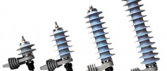
In relation to them, there are such abbreviations as OPN, OIN, OPS, etc. Typically, such devices contain one or more varistors inside, the resistance of which decreases sharply when the voltage reaches a certain limit. They are usually connected between the phase wire and the ground, but can also be additionally connected between the neutral wire and the ground. For example, the widely used UZP-220S protects against overvoltage on both phase and neutral wires. The main purpose of such devices is to protect against overvoltages caused by lightning discharges and switching processes.
Types and types of AFDP
With all this, GOST does not determine exactly how to do this. Each manufacturer solves the problem in its own way and issues appropriate patents.
Meander UZM 51MD
AFDD Eaton
UZIS-S1-40 Ecolight
Siemens 5SM AFD
ABB S-ARC1
Hager
Only when all factors are combined does the protective device determine that an arc has appeared in the circuit and turns it off.
If the pulses in the network are less than the specified amplitude, then this is considered not dangerous and the device does not respond.
Unlike the voltage relays we are used to, there are no manual settings on such arc-protective circuit breakers.
In voltage switches, you can adjust the triggering both at the upper and lower limits. Here, all parameters are set at the manufacturer’s factory.
Of course, the very first such specimens still have errors and false positives. The technology cannot be called fully developed.
However, most of the blunders have already been eliminated. For example, an ordinary vacuum cleaner, blender or drill, when turned on, can generate a certain wave characteristic similar to an arc. An arc also occurs when the stove is electrically ignited.
Any brushed power tool sparks, especially if its brushes are already worn out enough. Not to mention the initial inrush current.
Manufacturers take all these operating points into account and there are fewer and fewer false alarms in high-quality models.
How quickly should these arc flash detection devices respond? Everything here depends on the voltage and rating of the arc current.
According to the requirement of the IEC 62606 standard, at a current of 10A, the response time should not exceed 0.25 seconds.
Here is a table of all values:
Main types of relays and their purpose
Manufacturers configure modern switching devices in such a way that operation occurs only under certain conditions, for example, when the current flowing to the input terminals of the control unit increases. Below we will briefly look at the main types of solenoids and their purpose.
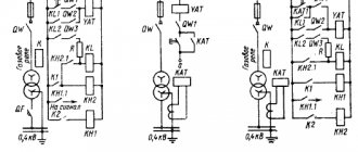
Electromagnetic relays
An electromagnetic relay is an electromechanical switching device, the operating principle of which is based on the effect of a magnetic field created by a current in a static winding on the armature. This type of control unit is divided into electromagnetic (neutral) devices, which respond only to the value of the current supplied to the winding, and polarized ones, the operation of which depends on both the current value and polarity.
Operating principle of an electromagnetic solenoid
Electromagnetic relays used in industrial equipment are in an intermediate position between high-current devices (magnetic starters, contactors, etc.) and low-current equipment. Most often this type of relay is used in control circuits.
AC Relay
This type of relay, as the name suggests, operates when an alternating current of a certain frequency is applied to the winding. This switching device for alternating current with or without phase zero crossing control is a block of thyristors, rectifier diodes and control circuits. AC relays can be made in the form of modules based on transformer or optical isolation. These KU are used in AC networks with a maximum voltage of 1.6 kV and an average load current of up to 320 A.
Intermediate relay 220 V
Sometimes the operation of the electrical network and devices is not possible without the use of a 220 V intermediate relay. Typically, a control unit of this type is used if it is necessary to open or open multidirectional contacts of a circuit. For example, if a lighting device with a motion sensor is used, then one conductor is connected to the sensor, and the other supplies electricity to the lamp.
AC relays are widely used in industrial equipment and home appliances
It works this way:
- supplying current to the first switching device;
- from the contacts of the first KU, the current flows to the next relay, which has higher characteristics than the previous one and is capable of withstanding currents with high values.
Every year relays become more efficient and compact
The functions of the small size 220V AC relay are very diverse and are widely used as an auxiliary device in a variety of fields. This type of control unit is used in cases where the main relay cannot cope with its task or when there are a large number of controlled networks that are no longer able to service the head unit.
The intermediate switching device is used in industrial and medical equipment, transportation, refrigeration equipment, televisions and other household appliances.
DC relay
DC relays are divided into neutral and polarized. The difference between them is that polarized DC ICs are sensitive to the polarity of the applied voltage. The armature of the switching device changes direction of movement depending on the power poles. Neutral DC electromagnetic relays are independent of voltage polarity.
Electromagnetic DC control units are mainly used when there is no possibility of connecting to an AC electrical network.
Four-pin automotive relay
The disadvantages of DC solenoids include the need to use a power supply and higher cost compared to AC control units.
This video demonstrates the connection diagram and explains the operating principle of a 4-pin relay:
Watch this video on YouTube
Electronic relay
Electronic control relay in the device circuit
Having understood what a current relay is, let’s consider the electronic type of this device. The design and principle of operation of electronic relays are practically the same as in electromechanical control units. However, to perform the necessary functions, an electronic device uses a semiconductor diode. In modern vehicles, most relay and switch functions are performed by electronic relay control units and at the moment it is impossible to completely abandon them. For example, a block of electronic relays allows you to control energy consumption, the voltage at the battery terminals, control the lighting system, etc.
Tags: , automatic, sconce, type, harm, choice, switch, engine, house, , protective, sign, cable, like, category, contactor, circuit, , magnet, installation, power, voltage, neutral, nominal, limiter, connection, potential, principle, wire, manufacturer, start, , work, regulator, resistor, relay, repair, row, light, lamp, LED, network, system, twist, resistance, means, stabilizer, circuit, ten, type, current , transformer, , installation, shield, electric motor, electronic, power supply, effect, anchor
Photo of the appearance of UZIS Ecolight
The appearance of the device is shown at the beginning of the article. Here is the side with the connection diagram:
UZIS Ecolight. Connection diagram
The connection diagram seems simple, but has one important feature! The fact is that, unlike other similar devices, the AFIS is connected from below, to the IN terminals, and the OUT output terminals are connected from above!
What the terminals look like:
Terminals for connecting ultrasonic devices. Reliable.
To check the functionality, the kit includes a means of monitoring the operating zone (sparking simulator):
Ultrasound control device - spark simulator
If you need to check the operation of the AFSI or if there is any suspicion of its malfunction, you can insert this device into any socket, and the AFSI should work.
Spark simulator for testing arc flash protection device
However, the UZIS has an internal control circuit that checks the device for functionality immediately after switching on and then every 12 hours.
A few more photos of the packaging. Informative and colorful.
The main causes of fires in electrical networks
I'm glad that such things are being done in Skolkovo!
UZIS Ecolight, box
UZIS Ecolight, packaging
Principle of operation
The UZM-51MD protective device operates according to the following algorithm. A 5-second time interval is maintained between the moment the voltage is applied and the transition to the ready mode. During this period, all indicators are turned off. If after checking the voltage is determined to be acceptable, the upper normal-failure indicator will flash green. From the time this LED turns on, a time delay begins, set by default to 10 seconds. After this, the load will be connected to the supply voltage. Switching on can be accelerated using the on-off button, which provides manual control.
In the event of an emergency shutdown, subsequent switching is performed automatically after normal voltage parameters are restored. There is also a delay of 10 s or 6 minutes. In the event of an accident, the load will not be able to be connected manually, since the relay will not allow this.
After establishing normal operating mode, the UZM monitors the voltage and parameters of the network with the connected load. With the advent of high-voltage pulse voltage, a varistor comes into operation, shunting it to levels that are not dangerous for the equipment.
If the voltage deviates from the operating limits, a delay begins to count, after which the load is turned off. For the upper limit it is 0.2 seconds, for the lower limit it is 10 seconds. If during these periods of time the voltage returns to the specified values, the time count will be reset and the load will not be disconnected.
When a spark or arc is detected in the network that exceeds safe operating limits in duration, the load will be switched off in emergency mode. Both the upper and lower indicators will light red. After 30 seconds the device will try to reconnect the load. If, after switching on for 20 minutes, signs of sparking are again detected, the load will be turned off again, but for 4 minutes. For the third time, the device completely disconnects the load until the fault is eliminated. After this, the load can only be turned on in manual mode.
Why do you need a spark protection device (USD)?
According to statistics, most fires and resulting fires occur due to faulty electrical appliances, as well as poor contact in parts of the circuit, such as adapters and extension cords. In this article we will talk about the spark protection device UZIS-S1-40 from, which precisely ensures recognition of sparks in the problem section of the circuit and produces timely shutdown, as well as protection of the controlled section.
Below we will describe in detail what an ultrasonic device is, how this device works and what its connection diagram is.
Design features
The device is manufactured for installation on a standard 35 mm DIN rail. The anti-sparking device has a non-separable IP40 housing with four contacts, IN and OUT for connection to the mains. On the right side of the case there is a diagram of the connection to the electrical network, with symbols of input and output, as well as the expected load.
On the front side there is a free release lever for turning on and off the protected circuit. There is also a regulator for setting the maximum permissible network voltage, from 260 to 290 Volts. For user interaction, an LED is displayed, by the indication modes of which you can determine the status of the device and the controlled network.
The IN (input) terminal is located at the bottom of the device, and the OUT (consumer output) terminal is located at the top. This solution is designed for ease of installation in the distribution board and saving space in it.
It is also worth paying attention to the fact that conductor L is switched in the device, and N connects the input and output without a break
The device comes complete with a means of monitoring the functioning of the protection zone, which simulates sparking in the network. It is made in the form of a plug for a standard outlet.
Using this device, you can determine the serviceability of the ultrasonic device, as well as monitor the functioning zone of the device protection (sensitivity of the device).
Using a monitoring tool, you can determine the ability of spark protection to sense the onset of dangerous processes at a certain distance, since on long lines the signal fades and is not detected by the protection device.
In the video below you can see the tests of the spark protection device, including ours:
Important! The operating area may be affected by interference from switching power supplies of electrical appliances. In this case, the manufacturer recommends connecting problem consumers through a standard 3-meter extension cord. In addition, the kit includes a sticker with a decoding of the UZIS indicator signals, which is pasted on the ShchR door
In addition, the kit includes a sticker with a decoding of the UZIS indicator signals, which is pasted on the ShchR door.
Main technical characteristics of the spark protection device:
To learn more about the device in question, we recommend watching the video:
Connection diagram
Possible connection options for UZIS-S1-40 are provided below:
Once installed and connected, no additional settings are required. When voltage is supplied to the network, the controller checks the value of the network voltage and the setting specified by the user. If everything is OK with the voltage, the green indicator light comes on.
Device light indication table:
Let's sum it up
Installing an ultrasonic protection system into the power supply protection and control system reduces the possibility of electrical wiring fire from unreliable contact and subsequent overheating of the problem area.
The spark protection device completely cuts off the possibility of using unqualified “scavengers and hacks” who do not comply with or are not familiar with the rules of the PUE, and also save money on clients. Therefore, the Sam Electric team recommends installation of the UZIS-S1-40.
In addition, when a dangerous voltage threshold in the network is exceeded, this device switches off, performing the function of a maximum voltage relay.
- Make a visual inspection and remove dust from the surface.
- Tighten the screws on the device in compliance with electrical safety rules.
- Check the performance of the AFIS using a control device at least once every six months.
Finally, we recommend watching a video that visually compares spark protection devices from different manufacturers:
As you can see, there are quite a lot of low-quality products on the market that will not be able to fully fulfill their main purpose - to protect wiring from fire when a spark occurs.
Therefore, it is important to give preference only to proven devices that have passed all tests and proven that they can cope with the main task.
Connection diagram
To begin with, here is a diagram of the AFDP itself:
Schematic diagram of the AFDD
Pay attention again - both in the diagram and in the real device, INPUT is from below, OUTPUT is from above!
The connection diagram for our device is simple, the main thing is to protect it automatically!
Connection diagram of the IEC AFZ through a circuit breaker
RCDs and difavtomats are connected according to the usual rules. As a result, the connection diagram will be like this:
Inclusion of an AFDD in a circuit together with a circuit breaker and an RCD
Instead of a combination of AB + RCD, you can use Difavtomat. Both options have their pros and cons, but that’s not about that now.
It is better to install an AFPD closer to consumers, in the apartment panel. This will ensure maximum sensitivity. At the same time, you need to understand that the AFDP will not detect any problems with the electrical wiring BEFORE the installation site.
Method of finding a sparking place
Sparking is a harbinger of fire. Therefore, if the spark protection device constantly trips, then you need to look for the location of the unstable contact
Attention should be paid to the following nodes:
- Distribution boxes. Open, look, look for the burning smell. If you turn off the voltage in the apartment, then you can test the twists for heating.
- Sockets, extension cords, plugs. They also get hot and smoke when heated.
- Apartment distribution board. The screws on the terminals of circuit breakers are often loose. As a result, poor contact with the wires and sparking occurs. Terminal blocks on automatic machines should be periodically tightened, but without fanaticism.
https://youtube.com/watch?v=ZYsLuwLibZY
Separately, the main signs of sparking contacts should be noted:
- crackling at the spark site;
- the smell of burning;
- overheating of connections;
- smoke;
- blinking light;
- crackling in the speakers of acoustic systems;
- light, sparks.
The operating principle of the AFDD is based on monitoring the state of voltage and current in the electrical wiring. Monitoring these parameters allows you to detect the appearance of sparks and arcs in strands and terminal blocks at an early stage and turn off the power supply to the apartment. As a result, the risk of wiring fires or damage to expensive consumer electronics is significantly reduced.
The arc protection device most closely resembles a voltage relay. Both protection devices have an upper and lower operating voltage limit. However, the AFDD has broader functionality, that is, it can detect sparks in twists and other unreliable burning contacts.
Uzis to the yard
As it turns out, things are not so simple in the YARD either. When it is triggered by sparking from an old drill, it’s understandable. But when the new Ferm FBH-620K rotary hammer turned off twice during an hour of work, I was completely disappointed in such a protection device! Moreover, it works both on key switches and when turning on/off the load through the plug connector (not always, but it turns off). A separate outlet will save you in some cases, but how can you know in advance what will trigger it?! You won’t always pull an extension cord from a separate one if there are already sockets nearby! In general, a hassle, according to the law of meanness, is triggered at the most inopportune moment. I don’t know what to do anymore, I’ll probably remove it completely.
Causes of fires and protection against them
Modern apartment electrical panels use many devices that are designed to increase safety.
- Automatic devices (circuit breakers) disconnect the consumer in the event of a short circuit or overload.
- Automatic devices disconnect the consumer in the same cases as automatic machines, but also when a current leak occurs, thereby protecting a person from electric shock.
- The RCD switches off in the event of a leak, but is only used in conjunction with a separate circuit breaker, since it is not built into it.
- Recently, a voltage relay began to be installed en masse in the panel, which monitors the voltage and turns off the consumer when the voltage goes beyond the established limits, thereby saving equipment from breakdown.
Not long ago, a new type of device was invented to minimize the possibility of a fire. They will be discussed further.
If you think about and analyze why a fire can occur, it turns out that most of it occurs due to a fault in the electrical wiring. Let's try to list all possible fire situations involving electricity:
- forgotten iron
- improper operation or malfunction of electric heating devices
- short circuit or wiring overload, but only if the machine for some reason did not work or worked late.
- voltage surges in the power supply network, which can cause malfunctions of household appliances, for example, breakdown of the insulation of filter capacitors, and as a result, a fire.
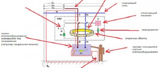
Sparking, also known as an electric arc, can occur due to various insulation faults or poor contact in connections. Heating and charring of insulation in places of poor contact and increased resistance causes charring of the insulation; charred insulation reduces its resistance, which further aggravates the heating effect. Thus, the charred parts of the insulation may begin to conduct current, followed by an avalanche-like increase in this process and the occurrence of an arc, which can cause a fire. In the first and second cases, the manufacturers of household appliances themselves take measures to eliminate the possibility of fire by installing all kinds of safety systems in them.
In more expensive irons, for example, they install a position and motion sensor that will turn off the iron in a horizontal position without movement in less than a minute, and in a vertical position without movement in a few minutes, which eliminates the human factor. For those who are forgetful, I recommend looking for just such an iron on sale.
Heaters usually have several overheating sensors and a sensor that monitors the correct operating position, namely a button that turns off the device when it tips over.
In case of overvoltage in the network, a voltage relay helps. It is triggered by increased voltage or a power surge.
For private homes, protection against power surges during thunderstorms is especially important. This voltage surge can be significant. For complete protection, varistor protection will help - OPS1-D or similar. A varistor absorbs energy during a voltage surge.
Causes of fire in electrical wiring
These devices detect the presence of a spark in the wiring and de-energize it. The main cause of fire in houses is not some kind of current leakage, from which fire-fighting RCDs are designed to protect (with a leakage current of 100-300 mA) and not even short circuits.
If the electrical installation is carried out correctly, the cross-section and rating of the machine are selected correctly, then the risk of fire occurring and spreading is minimal.
Most often, fires occur due to sparking wiring or an arc that occurs due to poor contact.
We can list 9 main reasons for these phenomena:
- mechanical damage to the cable
- loose contact, which appears not only after a long period of use, but also due to the use of the wrong tool
- crushed cable
- damage by rodents to hidden wiring behind hollow walls due to lack of protection with corrugated hose
- damage to external insulation and lack of basic protection in the form of electrical tape or thermal tube
- aging of insulation, which is promptly detected by special devices
- factory defect of a cable not manufactured in accordance with GOST
- poor contact (due to a bad socket or inappropriate plug)
- twisting of copper and aluminum
Moreover, sparking can occur even on a seemingly solid wire or cable. It was enough to make too sharp a bend during installation or accidentally place something heavy on it.
In principle, these problems and causes have been known for a long time, but the technology did not exist until the late 90s. They were first used in power grids in the USA and Western countries.
They are most widespread in wooden frame-type houses, where all wires, without any corrugations or pipes, are laid openly through flammable partitions.
Of course, such protection is not a panacea and will not save, for example, from elementary contact heating. If your plug does not spark in the socket, but only heats up, or the contact at the junction of the copper and aluminum wiring has oxidized, which also leads to heating, then a fire cannot be avoided and arc-protective devices will not help here.
Although, again abroad, they are gradually beginning to introduce sockets with built-in thermal protection. If they overheat, they automatically turn off.
True, such sockets are not required for installation anywhere else, even in the USA, and are installed on a voluntary basis.
Internal structure of the SPD
To disassemble the AFDD housing, it was necessary to drill out the flared racks.
The AFDC has been disassembled, the circuit board is visible
Printed circuit board - closer:
Printed circuit board of the AFDP, from the parts side
At the top right you can see the pads for the potentiometer (voltage relay limit switch), which is present in the Ecolight. Below are pads for connecting the controller programmer during production and a two-color LED.
The zero bus passes through the entire device from input to output, a petal is welded to it, and a blue wire is soldered to it to power the circuit.
On the top and bottom left of the board you can see the soldering of the input and output terminals. To view the board from the reverse side, you need to unsolder them.
Bent down the varistor:
Closer view of the board, view of the main chips
The inscriptions on the board are Ecolight, V1.6, RBNS758744.004.
NXP Controller:
Controller inside the AFDD
The device is quite complex, and it is not possible to put it back together:
Internal structure of the electromechanics of the SPD
A current transformer is placed on the phase wire near the input terminal. By constantly measuring current and voltage, the SPD controller monitors the state of the protected circuit. Also visible is an electromagnet that triggers the process to turn off the device when the controller so desires:
Electromagnet and transformer – execution and measurement devices
Thus, from this side there are two pairs of wires going to the board.
The coil and solenoid are closer, from a different angle
I also disassembled the control tool:
UZDP-SK control device in disassembled form
This is what an arc discharge simulator looks like:
Means for simulating sparking (arc discharge)
SPD classes
Today, all surge voltage devices are divided into three classes. And each of them plays its role.
The first class module dampens the main impulse; it is installed on the main input panel.
After the largest overvoltage has been extinguished, the residual impulse is taken over by a class 2 SPD. It is mounted in the distribution panel of the house.
If you do not have a Class I device, there is a high probability that the entire impact will be taken by the II module. And this could end very sadly for him.
Therefore, some electricians even discourage customers from installing impulse protection. Motivating this is that since you cannot provide the first level, then you should not spend money on it at all. There will be no point.
However, let's see what not a familiar electrician says about this, but the leading company for lightning protection systems, Citel:
That is, the text directly states that class II is mounted either after class 1, or AS AN INDEPENDENT DEVICE.
The third module directly protects a specific consumer.
If you do not want to build all this three-stage protection, purchase SPDs that are initially designed to work in three zones 1+2+3 or 2+3.
Such models are also produced. And they will be the most universal solution for use in private homes. However, their cost will certainly scare off many.
How to connect a usip in a private house
Here I present several typical connection diagrams for surge protection devices (SPDs). Below you will find single-phase and three-phase diagrams for different grounding systems: TN-C, TN-S and TN-CS. They are clear and understandable for the common man.
Today there are a large number of SPD manufacturers. The devices themselves come in different models, characteristics and designs. Therefore, before installing it, be sure to study the passport and connection diagram. In principle, the essence of connection for all SPDs is the same, but I still recommend reading the instructions first.
All laid out diagrams contain RCDs and group circuit breakers. I indicated them for clarity and completeness of the distribution panel. This “filling” of your shield may be completely different.
SPD connection diagram in a single-phase network of the TN-S grounding system.
This diagram shows an SPD of the Easy9 series from Schneider Electric. The following conductors are connected to it: phase, zero working and zero protective. Here it is installed immediately after the introductory machine. All contacts on any SPD are marked. Therefore, where to connect the “phase” and where to connect the “zero” can be easily determined. A green flag on the case indicates a working condition, and a red flag indicates a faulty cassette.
The presented device belongs to class 2. It alone is not capable of protecting against a direct lightning strike. Competent selection of SPDs is a complex and separate topic.
It is also recommended to protect SPD devices with fuses.
I think everything is clear here.
Below is a similar diagram for connecting an SPD, but without an electric meter and using a common RCD.
SPD connection diagram in a three-phase network of the TN-S grounding system.
The diagram also shows an SPD manufactured by Schneider Electric of the Easy9 series, but for a 3-phase network. The figure shows a 4-pole device with a neutral working conductor connected.
There is also a 3-pole SPD of the same series. It is used in the TN-C grounding system. It does not have a contact for connecting the neutral working conductor.
SPD connection diagram in a three-phase network of the TN-C grounding system.
The SPD from IEK is shown here. This diagram is a regular input panel for a private house. It consists of an input circuit breaker, an electric meter, an SPD and a general fire protection RCD. The diagram also shows the transition from the TN-C to TN-CS grounding system, which is required by modern standards.
The first picture shows a 4-pole input circuit breaker, and the second picture shows a 3-pole one.
There is no more permanent connection than a temporary twist!