| d = | cm |
| h = | cm |
| Primary voltage | |
| U = | IN |
set the parameters of the secondary windings
|
|
Sst f is the cross-sectional area of the magnetic circuit. Calculated using the formula: Sst = h * (D – d)/2. Sok f – actual window area in the existing magnetic circuit. Calculated using the formula: Sok = π * d 2 / 4. Knowing these values, you can calculate the approximate power of the transformer: Pc max = Bmax *J * Kok * Kst * Sst * Sok / 0.901 Source |
Quick calculation of a toroidal power transformer
Simplified calculation of toroidal power transformers
You can quickly and with fairly high accuracy calculate a power transformer on a toroidal core using the following method.
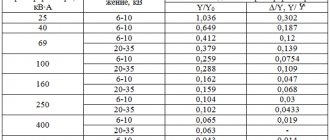
- Total power ( P ) is defined as the sum of the powers of all secondary windings of the transformer, divided by the efficiency (efficiency) of the toroidal transformer, which is determined according to Table 1.
Section coefficient (j)
| Overall power |
The formula for determining overall power ( Pg ) is as follows:
The cross-sectional area of the core of a toroidal transformer is calculated using the formula:
Where j is the section correction factor determined from Table 1.
Based on the obtained value ( Sp ), the most suitable toroidal core in size is selected from Table 1 in the “Toroidal Magnetic Cores” section. Moreover, the toroidal core is selected in such a way that the internal diameter of the core is greater than or equal to the calculated value dr .
Next, according to Table 2, select the value of the coefficient g, which will be used to calculate the number of turns per volt. Table 2 shows the values of the g coefficient depending on the steel used in the core and the overall power of the transformer.
Source
Type of devices
There are several types of transformers, which are divided according to design and purpose:
Autotransformers
In such devices there are several terminals from one winding, receiving different voltages. The advantage is the lowest cost due to the low consumption of wire for the windings, steel for the magnetic core, resulting in less weight compared to other types of transformer devices.
Power
The most popular type of industrial transformers used in power lines to increase or decrease voltage.
Pulse
Designed to change a pulse signal of insignificant duration (up to tens of microseconds) with the assumption of minimal deviation of the pulse shape.
Separating
Designed for safe supply of mains power to consumers and elimination of voltage surges in the network.
Current transformer
A remote version of current transformers, which can be of different sizes and with different performance indicators. Designed for measurement and control, as well as protection of devices.
Transformer calculation: online calculator or old-fashioned method for home - choose yourself
Repair of modern electrical appliances and the manufacture of home-made structures are often associated with power supplies, chargers and other devices that use transformer energy conversion. Their condition must be analyzed and assessed.
I believe that an online calculator that works according to a prepared algorithm, or the old proven old-fashioned method with formulas that requires a thoughtful attitude, will help you calculate the transformer. Try both methods, use the best one.
I immediately draw your attention to the issue that the given methods are not able to accurately take into account the magnetic properties of the core, which can be made of different types of electrical steel.
Therefore, the actual electrical characteristics of the assembled transformer may differ by several volts or the number of amperes from the obtained calculated value. In practice, this is usually not critical, but can always be corrected by changing the quantity number in one of the windings.
The cross section of the magnetic circuit transfers the primary energy by magnetic flux to the secondary winding. Possessing a certain magnetic resistance, it limits the transformation process.
The shape, material and cross-section of the core determines the power that can be converted and normally transmitted to the secondary circuit.
How to use an online calculator to calculate a transformer step by step
Preparing source data in 6 simple steps
Step #1. Specifying the core shape and cross-section
Cores made from W-shaped plates have the best distribution of magnetic flux. The ring shape of U-shaped components has great resistance.
To carry out the calculation, you need to indicate the shape of the core according to the type of plate (by clicking on the point) and its measured linear dimensions:
- The width of the plate under the coil with winding.
Thickness of the assembled package.
Paste this data into the appropriate table cells.
Step #2. Voltage selection
The transformer is created as a step-up, step-down (which is in principle reversible) or separating structure. In any case, you need to indicate what voltages you need on its primary and secondary windings in volts.
Fill in the indicated cells.
Step #3. AC signal frequency
By default, the standard household network value is set to 50 hertz. If necessary, it must be changed to that required by another calculation. But, this technique is not intended for high-frequency transformers used in switching power supplies.
They are created from other core materials and calculated in different ways.
Step #4. Efficiency
For conventional models of dry-type transformers, the efficiency depends on the applied electrical power and is calculated as an average value.
But, you can adjust its value manually.
Step #5. Magnetic inductance
The parameter determines the dependence of the magnetic flux on the geometric dimensions and shape of the conductor through which the current flows.
By default, the average parameter of 1.3 Tesla is adopted for calculating transformers. It can be adjusted.
Step #6. Current Density
The term is used to select the winding wire according to operating conditions. The average value for copper is 3.5 amperes per square millimeter of cross-section.
To operate the transformer in conditions of increased heating, it should be reduced. For forced cooling or reduced loads, it is permissible to increase. However, 3.5 A/mm kV is quite suitable for household devices.
Performing online transformer calculations
After filling in the cells with the original data, click on the “Calculate” button. The program automatically processes the entered data and displays the calculation results in a table.
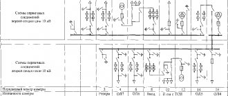
Groups and connection diagrams of windings
Transformer devices are divided into groups of winding connections. The choice of winding connection diagram depends on the operating conditions of the device.
In the diagrams, the transformer is depicted as several coils, between which a line is drawn.
Coil Ⅰ denotes the primary winding to which voltage is applied to increase or decrease it. On the secondary windings ( Ⅱ and Ⅲ ) it is shown where the low or high voltage level is removed. Thus, there can be several secondary windings.
The vertical line between the windings indicates the magnetic core - the magnetic circuit.
How to calculate a power transformer using formulas in 5 steps
I present a simplified method that I have been using for several decades to create and test homemade transformer devices made from iron of an unknown brand in terms of load power.
Using it, I almost always managed to wind the circuit on the first try. Very rarely it was necessary to add or reduce a certain number of turns.
Stage No. 1. How does the power of a dry-type transformer affect the shape and cross-section of the magnetic circuit?
The calculation is based on the average efficiency ratio ŋ, as the ratio of the electrical power S2 converted in the secondary winding to the applied total power S1 in the primary.
Power losses in the secondary winding are estimated using a statistical table.
| Transformer power, watts | Efficiency ŋ |
| 15÷50 | 0,50÷0,80 |
| 50÷150 | 0,80÷0,90 |
| 150÷300 | 0,90÷0,93 |
| 300÷1000 | 0,93÷0,95 |
| >1000 | 0.95÷0,98 |
The electrical power of the device is determined by the product of the rated current flowing through the primary winding in amperes and the household wiring voltage in volts.
It is converted into magnetic energy flowing through the core, fully distributed in it depending on the shape of the flow distribution:
- for a ring figure of U-shaped plates, the cross-sectional area under the magnetic circuit coil is calculated as Qc=√S1;
- for a core made of Ш-shaped plates Qc=0.7√S1.
Stage No. 2. Features of calculating the transformation ratio and currents inside the windings
A power transformer is created to convert electrical energy from one voltage value to another, for example, U1=220 volts at the input and U2=24 V at the output.
The transformation ratio in the above example is written as the expression 220/24 or a fraction with the primary voltage value in the numerator and the secondary voltage in the denominator. It also allows you to determine the ratio of the number of turns between the windings.
At the first stage, we have already determined the electrical power of each winding. Using them and the voltage value, it is necessary to calculate the strength of the electric current I=S/U inside any coil.
Stage No. 3. How to calculate the diameters of copper wire for each winding
When determining the cross-section of the coil conductor, an empirical expression is used, taking into account that the current density lies in the range of 1.8÷3 amperes per square millimeter.
We determined the current value in amperes for each winding in the previous step.
Now we simply take the square root of it and multiply by a factor of 0.8. We write the resulting number in millimeters. This is the estimated wire diameter for the coil.
It is selected taking into account the release of permissible heat due to the current flowing through it. If space in the core window allows, the diameter can be slightly increased. Then these windings will be better adapted to thermal loads.
When, even with tight winding, all the turns of the wire do not fit into the window of the magnetic circuit, then its cross-section can be slightly reduced. But, such a transformer should be used for short-term operation and subsequent cooling.
Stage No. 4. Determining the number of turns of windings according to the characteristics of electrical steel: important points
The calculation is based on the magnetic properties of the iron core. Industrial transformers are assembled from different types of electrical steel, selected for specific operating conditions. They are calculated using complex, individual algorithms.
The home handyman gets magnetic cores of an unknown brand, the electrical characteristics of which are practically impossible for him to determine. Therefore, the formulas take into account average parameters, which are not difficult to adjust during setup.
For the calculation, an empirical coefficient ω' is introduced. It takes into account the magnitude of the voltage in volts, which is induced in one turn of the coil and is associated with the cross-section of the magnetic circuit Qc (cm kV).
In the primary winding, we calculate the number of turns as W1= ω'∙U1, and in the secondary - W2= ω'∙U2.
Stage No. 5. Taking into account the free space inside the magnetic circuit window
At this step, you need to estimate whether all the windings will fit into the free space of the core window, taking into account the dimensions of the coil.
To do this, we assume that the wire does not have a round cross-section, but a square with a side of the same diameter. Then, with absolutely ideal dense packing, it will occupy an area equal to the product of the unit section and the number of turns.
We increase this area by 30 percent, because it will not be possible to wind the turns perfectly this way. This will be a place inside the cavities of the coil, and it will still take up a certain space.
Next, we compare the resulting areas for the coils of each winding with the window of the magnetic circuit and draw conclusions.
The second way to evaluate is to wind the coils “for luck.” It can be used if the new design is rewound with wire from old working coils on the same core.
Selection of current transformers
Current transformers are selected according to rated voltage, rated primary current and tested for electrodynamic and thermal resistance to short-circuit currents. A feature of the selection of current transformers is the selection according to the accuracy class and checking for the permissible load of the secondary circuit.
Accuracy classes of current transformers
- Current transformers for connecting meters for which cash payments are made must have an accuracy class 0,5.
- For technical accounting, it is allowed to use current transformers of accuracy class 1;
- To turn on indicating electrical measuring instruments - not lower than 3 ;
- For relay protection - class 10(P) .
To ensure that the current transformer error does not exceed the permissible value for a given accuracy class, the secondary load Z2 should not exceed the rated load Z2nom specified in the catalogs.
The inductive reactance of such circuits is small, so they take Z2p = r2p. The secondary load g2 consists of the resistance of the devices g prib, the connecting wires gpr and the contact resistance gk:
To determine the resistance of devices powered by current transformers, it is necessary to draw up a table - a list of electrical measuring instruments installed in a given connection.
The total resistance of devices, Ohm, is calculated based on the total power:
In 6-10 kV switchgear, transformers with /2nom = 5A are used; in switchgear 110 - 220 kV - 1 or 5 A. The resistance of the main contacts is 0.05 Ohm for two or three devices and 0.10 for more devices. The resistance of the wires is calculated by their cross-section and length. For aluminum wires, the minimum cross-section is 4 mm2; for copper - 2.5 mm2.
The estimated wire length depends on the connection diagram of the current transformer and the distance l from the transformer to the devices:
- when switching current transformers into an incomplete star;
- 21 - when all devices are turned on in one phase;
- l - when turning on current transformers in a full star.
In this case, the length l can be taken approximately for switchgear 6-10 kV:
- when installing devices in switchgear cabinets / = 4… 6 m;
- on the control panel /= 30…40 m;
- for RU 35 kV / = 45…60 m;
- for RU PO - 220 kV/ = 65...80 m.
If, with the accepted wire cross-section, the secondary resistance of the current transformer circuit turns out to be greater than ZHOU for a given accuracy class, then it is necessary to determine the required wire cross-section taking into account the permissible resistance of the secondary circuit:
where p is the resistivity.
The resulting cross-section is rounded up to a larger standard cross-section of control cables: 2.5; 4; 6; 10 mm2.
The conditions for selecting a current transformer are given in table. 7.5. Additionally, the following can be specified: KTN = 1t.tn/UR21nom - multiplicity of the dynamic resistance current of the current transformer; CT = /Т//|„ОМ – thermal resistance current multiplicity; /i„OM - rated current of the primary winding of the current transformer.