Features of Line Voltage
Electrical circuits are characterized by the presence of different types of voltage. Linear voltage (LV) occurs between the phase conductors of a three-phase circuit. All parts (phases) of a multiphase circuit have an identical current characteristic. The name of the circuits (six-, three- or 2-phase) is determined by the number of phases. Three-phase electrical circuits are most widespread, as they are the most economical in comparison with multiphase or 2-phase ones. They also make it possible to obtain LN and phase voltage (PV) on one unit.
What is a phase
Each part of a multiphase system that has the same current characteristic is called a phase. Therefore, determining the phase has a double meaning in electrical engineering. Firstly, as a quantity that changes sinusoidally, and secondly, as a separate part in a system of multiphase electrical circuits. The number of phases determines the name of the circuits: two-phase, three-phase, six-phase, etc.
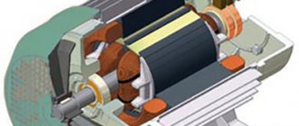
The most common circuits in modern energy are three-phase. They have a number of advantages over other types of circuits, both single-phase and multiphase. They are more economical in the production and transmission of electricity. Three-phase voltage occurs as a result of the rotation of the magnet inside the coil. With its help, a rotating circular magnetic field is quite simply formed, ensuring the operation of asynchronous motors. This phenomenon is known as EMF or in other words, electromotive force of induction.
The rotating magnet is called the rotor, and the coils placed around it form the stator. AC voltage is obtained by converting DC voltage where the straight line takes on a sinusoidal configuration with varying positive and negative values.
The change in magnetic flux occurs due to rotation of the rotor, which leads to the formation of alternating voltage. The stator has three coils, each of which has its own separate electrical circuit. Each coil is shifted relative to each other by 120 degrees around the circumference. Under the influence of a rotating magnet, the same alternating voltage between phases in a three-phase network arises in all coils.
Three-phase circuits make it possible to obtain two operating voltages in one installation - phase and linear.
Which voltage is called linear and which phase?
Linear is the voltage between 2 phases of a line or when the value between 2 wires of different phases is determined.
The voltage between any phase and zero is phase. It is measured between the initial and final stages of the phase. In practice, FN differs from LN by 58-60 percent. That is, the LN values are 1.73 times greater than the FN values.
Three-phase circuits have 380V LN, which allows you to get 220V phase.
Options for determining phase/neutral conductors
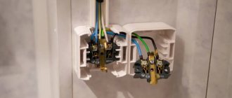
So, a situation has come when it is necessary, for example, to connect a new outlet. But it is not at all clear which of the wires is phase and which is neutral. There are several ways to quickly solve the problem - this can be done both with the use of special devices and without them.
Color coloring of wires as a main guide
This is the easiest and fastest way. To correctly classify zero and phase, you should know which wire color belongs to what. You will first need to study information about where the current standards for a particular country are clearly stated.
This method is very relevant in any new buildings, since now all electrical wiring is laid by specialists who carry out their work in accordance with all the requirements of established standards. For example, in Russia back in 2004, the “IEC60446” standard was adopted, which clearly defines the procedure for separating cables by color, namely:
- a yellow-green wire began to be designated as a protective zero;
- the working zero began to be called the blue/blue-white wire;
- phase - wires of other colors (for example, black, red, brown and others).
This designation is currently relevant.
If the wiring is already quite old or its installation was carried out by non-professional specialists, it would still be more correct to use other methods of determination.
An indicator screwdriver is an indispensable device
This tool is an integral part of the home electrician's kit. It is used both when performing electrical installation work, and when installing lighting fixtures indoors, or even in the process of simply replacing light bulbs.
The principle of its operation is the passage of capacitive current through the body of the screwdriver through the operator’s body.
Screwdriver elements:
- housing made of dielectric material;
- a metal tip in the shape of a flat screwdriver, which is applied to the wires when checking;
- neon indicator - a light bulb signaling the phase potential;
- current limiter - a resistor that reduces the current to a minimum value and acts as a protective mechanism: it protects a person from electric shock, and the device itself from failure;
- a contact metal pad that creates a closed circuit through a person to the ground.
The method of work is so simple that anyone, even a beginner, can cope with it. The indicator screwdriver works as follows. When the tip touches the phase contact (colored wire), the electrical circuit is closed - the neon lamp should light up. That is, a “message” is received about the presence of resistance, therefore, this cable is a phase. At the same time, it should not light up either at ground or at zero. If this happens, we can say with confidence that there are errors in the wiring diagram.
Working with an indicator screwdriver during daylight hours will require some care - during the day the glow of the lamp is difficult to see, so you will have to look closely.
When working with such devices, you need to be extremely careful - do not touch exposed areas of conductors and indicator terminals that are under voltage.
On a note! Professional electricians use more expensive multifunctional indicators, the glow of which is controlled by a transistor circuit powered by built-in 3 V batteries. Another characteristic difference from simple analogues is the absence of a contact pad that needs to be touched when taking measurements.
The devices, in addition to their direct purpose - checking the phase wire - also perform a number of other auxiliary tasks: determining the polarity of DC voltage sources, the location of an electrical circuit break, and so on.
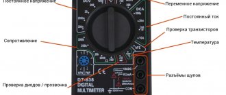
Multimeter - a reliable assistant
To calculate the phase using a tester, you need to switch it to the “voltmeter” mode and measure the voltage between all paired cable terminals. The connection of the probes to the protective zero and ground should indicate the absence of voltage. The voltage between the phase and any other wires should be 220 V.
Ways to identify wires:
So, in the first case, the voltmeter deviates from zero o. In another picture it shows the absence of voltage between zero and ground. And on the third, the voltmeter between the phase and the ground shows “0 V” since the conductor is not yet connected to the ground. The third case is rather an exception to the rule. This is possible, for example, in cases where the old cables of the building are at the stage of reconstruction. In a normal working electrical wiring system, the voltmeter should also show 220 V.
Using an incandescent lamp
Before starting work, you will need to assemble the testing device. It will consist of an ordinary light bulb, socket and wires. The lamp is screwed into the socket, and conductors are attached to the terminals of the socket. One of the wires will need to be grounded, for example, connected to a heating battery.
The essence of the method is to alternately apply a second (free) conductor to all tested conductors. If the light flashes, a phase wire has been found.
The method allows you to determine approximately the presence of a phase cable among the others. The lamp signal accurately indicates that among these conductors some are phase and some are neutral. If the lamp does not light, then there is no phase cable among the cables. But it may happen that there is precisely zero.
Therefore, to a greater extent, this method is appropriate for determining the functionality of electrical wiring and correct installation.
Differences
The specificity of the LN is an indicator by which currents and other quantities of a three-phase circuit are calculated. This scheme allows you to connect single- and three-phase contacts. The nominal value is 380V and changes with changes in a limited network, for example, due to surges.
The most popular is a circuit with a neutral and grounding. Connection in such a system is made according to the following scheme:
- Single-phase wires are connected to phase wires;
- to 3-phase - 3-phase.
The breadth of use of LN is determined by its safety and convenience of chain branching. In this case, the equipment is connected to the phase output, and only this is not safe.
Calculation of the system is simple; standard physical formulas apply. The parameters of the LN network are measured with a multimeter, and the FN parameters are measured with special devices, for example, a voltmeter, a current sensor, or a tester.
- The wiring of such wiring does not require the use of professional equipment. Screwdrivers that have indicators are sufficient.
- The risk of electric shock is very low. This is explained by the free neutral present in the circuit. The connection of conductors does not require connecting the 0th pin.
- The circuit is suitable for all types of current.
Important! A 1-phase circuit can be connected to a 3-phase circuit. The opposite cannot be done.
- This connection scheme is suitable for many devices that require high power to operate. LN allows you to increase engine efficiency by 33%.
When switching the generator windings to a triangle from a star, it causes an increase in the value of LN by 1.73 times.
Important! The difficulty of detecting damage in a linear connection is an important disadvantage of the circuit, since this can result in a fire.
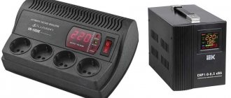
The difference between LN and FN is the difference in the connected winding wires. To control the parameters of LN and FN, you will need a pulse stabilizer, or, in other words, a linear stabilizer. This device makes it possible, while maintaining the indicator at the same level, to normalize the voltage if it has increased sharply. The device can be connected to the contacts of electrical equipment, a regular outlet.
Ratio of phase and line voltage
The ratio between line and phase voltage is 1.73. That is, at one hundred percent of the LN power, the phase voltage will be 58%. That is, LN exceeds FN by 1.73 times and is stable.
The voltage in a three-phase circuit is estimated based on the parameters of the linear component. Usually it is 380 volts and is identical to 220 volts of the phase component of a three-phase electric current network. In electrical networks where there are four wires, the 3-phase voltage is designated 380/220V. This allows you to connect to such a network equipment with 1-phase electricity consumption of 220V and powerful devices that can operate on 380V.
A three-phase circuit with 380/220V 0 wire is universal and acceptable in most cases. Electrical appliances that operate on a single-phase voltage of 220V can, when connected to a pair of FN wires, be powered by the LN.
Electrical equipment that is powered from a three-phase network can only work if there is a connection simultaneously to 3 terminals of different phases. Then grounding is not necessary, but if the insulating material of the wire is damaged, then the absence of 0 significantly increases the risk of electric shock.
Important! As the LN decreases, the FN values change. With the value of the phase-to-phase voltage already determined, it will not be difficult to determine the value of the FN.
Electrical voltage and its parameters
Current can be variable or stable. The changing one can be different, the main thing is that its polarity and power changes over time. A stable current always has the same polarity, and the power can be stable or not.
In standard sockets, the current power varies, the sine wave is offensive. There are several meanings: instantaneous (instantaneous), with increasing (amplitude) and working (effective).
Instantaneous is the required current strength at a certain moment. With increase or amplitude is the width of the current power.
Working or acting is the quadrature of the power function over time. The percentage ratio can be expressed as follows: the operating value is 2 or 1.41 times less than the amplitude.
What is it measured in?
According to GOST 13109, the voltage standard in the electrical network varies in the range from 198V to 242V (that is, 220V plus or minus 10 percent). If household appliances, lamps often break down or flicker, you will need to measure the voltage in the electrical wiring. A similar check is done with a multimeter or voltmeter. At night, when electrical appliances are used to a minimum, the values obtained will be maximum.
A multimeter measures the voltage in a three-phase network as follows:
- Between working 0 and each of the phases: A-N, B-N, C-N.
- Linear voltages: A-B, A-C, B-C.
There should be six dimensions in total. Sometimes another measurement is made - between the grounding and neutral working conductor: N-PE.
How to measure
You can measure such a system with a multimeter or using physical formulas.
LN is calculated using the Kirchhoff formula: ∑ Ik = 0. Here the current strength is zero in all parts of the electrical circuit, that is, k = 1. Ohm's law is also used: I=U/R. By applying both formulas, you can calculate the parameters of the brand or electrical network.
In a system of several lines, you will need to find the voltage between 0 and phase IL = IF. The IL and IF values are not constant and change with different connection variations. Therefore, the linear parameters are exactly the same as the phase ones.
Phase
In order to obtain phase connection readings, you will need special equipment, for example, a multimeter, voltmeter. In order to measure currents and voltages in three-phase circuits, it is usually enough to know the data of one linear current and one linear current.
FN is measured when the linear sag (falls). The square root of three is taken from linear quantities. The resulting indicator is the parameters of the physical function.
What are the main differences between linear and phase voltage?
One type of system with multiple phases is represented by circuits consisting of three phases. They operate with electromotive forces of a sinusoidal type, arising at a synchronous frequency, from a single energy generator, and have a difference in phase.
By phase we mean independent blocks of a system with multiple phases, having current parameters identical to each other. Therefore, in the electrical field, the definition of phase has a double interpretation.
Firstly, as a value that has a sinusoidal oscillation, and secondly, as an independent element in an electrical network with many phases. In accordance with their quantity, a specific circuit is marked: two-phase, three-phase, six-phase, etc.
Today in the electric power industry, the most popular are circuits with three-phase current. They have a whole list of advantages that distinguish them from their single-phase and multiphase analogues, since, firstly, they are cheaper in terms of technology for installing and transporting electricity with minimal losses and costs.
Secondly, they tend to easily form a magnetic field moving in a circle, which is the driving force for asynchronous motors, which are used not only in enterprises, but also in everyday life, for example, in the lifting mechanism of high-rise elevators, etc.
Electric circuits with three phases allow you to simultaneously use two types of voltage from one source of electricity - linear and phase.
Three-phase network elements
The main elements of a three-phase network are a generator, an electrical energy transmission line, and a load (consumer). To consider the question of what linear and phase voltage is in a circuit, we will give a definition of what a phase is.
A phase is an electrical circuit in a system of multiphase electrical circuits. The beginning of the phase is the terminal or end of the electrical conductor through which the electric current enters it. Experts have always distinguished electrical circuits by the number of phases: single-phase, two-phase, three-phase and polyphase.
Types of electrical circuits, their classification:
The most commonly used is three-phase connection of objects, which has a significant advantage over both multiphase circuits and single-phase circuits. The differences are as follows:
- lower costs for transporting electrical energy;
- the ability to create an EMF for the operation of asynchronous motors - this is the operation of elevators in multi-storey buildings, equipment in the office and in production;
- This type of connection makes it possible to simultaneously use both linear and phase voltage.
Types of voltage
Knowledge of their features and operating characteristics is extremely necessary for manipulations in electrical panels and when working with devices powered by 380 volts:
- Linear. It is designated as interphase current, that is, passing between a pair of contacts or identical marks of different phases. It is determined by the potential difference of a pair of phase contacts.
- Phase. It appears when the initial and final terminals of a phase are short-circuited. Also, it is designated as the current that occurs when one of the phase contacts with the zero terminal is closed. Its value is determined by the absolute value of the difference between the leads from the phase and the Earth.
Differences
In an ordinary apartment or private house, as a rule, there is only a single-phase type of network 220 volts , therefore, basically two wires are connected to their power supply panel - phase and zero, less often a third is added to them - grounding.
High-rise apartment buildings with offices, hotels or shopping centers are supplied with 4 or 5 power cables at once, providing three phases of a 380 volt network.
Why such a strict division? The fact is that three-phase voltage, firstly, is itself characterized by increased power, and secondly, it is specifically suitable for powering special heavy-duty three-phase electric motors, which are used in factories, in electric elevator winches, escalator lifts, etc.
When connected to a three-phase network, such motors produce many times more force than their single-phase counterparts of the same dimensions and weight.
When connecting conductors, you do not need to mount a zero contact , because the probability of breakdown is very low, thanks to the unoccupied neutral.
But such a network diagram also has its weak point, since in a linear installation diagram it is extremely difficult to find the location of conductor damage in the event of an accident or breakdown, which can increase the risk of a fire.
Thus, the main difference between the phase and linear types is the different wiring diagrams for connecting the windings of the source and consumer of electricity.
Three-phase circuit diagrams
The windings of a generator or transformer in three-phase circuits can be connected to each other according to two schemes:
- star;
- triangle.
Connections are made on the terminal block (boron) of the unit or transformer, where the ends of the windings are brought out.
Jumper connection of windings
Connecting the load to the generator (transformer) can be done according to the following schemes:
- star-star connection using a neutral conductor;
- star-star connection without using a neutral wire;
- star-delta connection;
- "triangle-triangle" scheme;
- delta-star connection.
Attention! This variety of circuits is due to the fact that the generator's own windings and the load's own windings can be connected in different ways. With different types of coupling, different correspondences between phase and linear values are obtained.
The connection can be made at the factory when assembling the generator; the second ends of the windings are already brought out to the point where the power cable is connected. Information about the winding connection diagram is applied to a plate attached to the stator of the machine.
On electric motors, transformers or other consumers, the necessary manipulations are also performed to switch winding terminals. In the picture below, the ends of the windings connected by a jumper are marked with a red marker. Blue marker - power phases.
Star connection
The letter designation of the beginning of the windings is “A”, “B”, “C”, the ends are “X”, “Y”, “Z”. The zero point is marked “O”. Each winding has two ends. When connecting “star”, all three winding terminals of the same name (beginning) are connected to each other at one point “O”. The load is connected to the free ends.
Star winding connection diagram
Delta connection
When making this connection, jumpers are placed on the board, turning on the windings in the following sequence:
- the end of “A” - with the beginning of “B”;
- end “B” – with beginning “C”;
- the end of "C" - with the beginning of "A".
The graphic image of the coils becomes similar to a triangle, hence the name.
When they want to use a plug-in asynchronous motor with maximum efficiency, its windings are connected in a triangle. In this case, the phase voltages coincide (Ul = Uph), the line current will be calculated by the formula:
Il = √3*Iph.
When connecting a motor as a load, it is necessary to take into account a number of nuances:
- an increase in power by 1.5 times is achieved;
- the value of the starting current increases 7 times compared to the operating current due to difficult starting;
- a sharp increase in the load on the electric machine shaft will cause a sharp increase in current.
Because of all this, there is a risk of the machine overheating, which does not happen when the load windings are connected in a star configuration. There, the engine is not prone to overheating, and it starts smoothly.
Switching on the windings according to the "triangle" pattern
With two types of winding connection, two types of currents are distinguished and defined: linear and phase. It's easy to remember the differences:
- the current flowing through the conductor that connects the source to the receiver is called linear;
- The current moving through the windings of the source or load is called phase.
It is worth paying attention to the power formulas for various schemes for connecting the source to the load.
The current power in a star circuit is determined by the formula:
P = 3*Uф*Iф*cosϕ = √3*Uл*Iл*cosϕ,
Where:
- Uph – phase voltage;
- Uл – linear voltage;
- Iph – phase current;
- Il – linear current;
- cosϕ – phase shift.
The current power in a delta circuit is calculated by the formula:
P = 3* Uф* Iф*cosϕ = √3*Uл*Iл*cosϕ.
For your information. It is necessary to pay attention to linear and phase currents when the generator (source) is loaded asymmetrically when the load is connected.
Connections in a three-phase circuit
Ratio
The phase voltage value is equal to about 58% of the power of the linear analogue . That is, under normal operating parameters, the linear value is stable and exceeds the phase value by 1.73 times.
The assessment of voltage in a three-phase electric current network is mainly carried out based on the indicators of its linear component. For current lines of this type supplied from substations, it is usually equal to 380 volts, and is identical to the phase analogue of 220 V.
In electrical networks with four wires, the three-phase current voltage is marked with both values - 380/220 V. This makes it possible to power devices from such a network, both with single-phase electricity consumption of 220 volts, and more powerful units designed for a current of 380 V.
The most accessible and universal system has become a three-phase type 380/220 V system , which has a neutral wire, the so-called grounding. Electrical units operating on a single phase of 220 V can be powered from line voltage when connected to any pair of phase terminals.
In this case, the use of the neutral terminal as grounding is not necessary, although in the event of damage to the wire insulation, its absence seriously increases the likelihood of an electric shock.
Three-phase voltage 380V. On the electrification of residential buildings.
In this article we will talk about the electrification of residential buildings, what three-phase voltage 380V is and how 220V voltage is obtained from it.
A number of household electrical appliances require connections other than a conventional lamp, hair dryer, vacuum cleaner, soldering iron. Such non-standard devices include, firstly, devices that require protective grounding (computers, automatic washing machines), secondly, high-power devices (electric kettles, air conditioners, microwave ovens, stoves, ovens, water heaters) and thirdly, these are appliances , requiring special electrical wiring for connection - three-arm (or more) chandeliers.
Proper connection of the above-mentioned household appliances and devices to the electrical network is very important, since failure to follow the rules for connecting them can lead to fire, electrical injury or failure of the device. Below we will look at the protective grounding device (grounding) and the installation of a special electrical protection device - a residual current device (RCD) for connecting a computer and an automatic washing machine, a device and rules for protecting the electrical network from overloads for connecting powerful electrical appliances , as well as a wiring diagram for connecting a multi-arm chandelier .
So, if you look at the plug of any modern electrical appliance, you will see that it is made of the so-called. to the European standard, i.e. it has not two, but three contacts for connecting to a three-wire plug socket, or to a European socket. Why do you need a third wire in a European socket and a plug for it, and what is so special hidden in the design of devices designed specifically for such a connection?
In order to understand the difference in the number of wires in various sockets, as well as the purpose of grounding and protective grounding and the operation of protective devices, you need to know exactly how the wiring in our houses goes from the supply generator or transformer substation to the distribution panels of our apartments.
The current that goes directly to the generator or transformer substation differs significantly from the current that we have in sockets, switches and other installation points of electrical appliances in our apartments, although the same alternating current with a frequency of 50+-0.1 Hz (this frequency and such tolerance is at least established in the relevant regulatory documents).
However, the current coming from a generator or transformer substation, unlike the current in the residential electrical network, is three-phase, i.e., it is the sum of three alternating currents, but the phase is shifted by 120 degrees , which means that the maximum voltages of the three-phase current components do not coincide, a are shifted relative to each other by 1/3 of the oscillation period. Each component of a three-phase current component has the abbreviated name “phase” .
The stator windings of a three-phase current supply generator or the secondary windings of a transformer at a substation are connected by a “star ,” i.e., their three ends are connected at one common point. The other ends of the windings are free, and wires called phase (there are three in total). , phase wires are designated L1, L2, L3 , respectively, and the phase wire of a single-phase circuit is simply designated L.
Three-phase voltage
diagram With such a circuit for connecting the windings of a generator or transformer, only a certain class of electrical appliances can be connected to the current source, designed to be powered by alternating three-phase current and structurally ensuring equality of the load of all three phases. However, such electrical appliances, due to their high cost, material and labor-intensive manufacturing, the need to fulfill the condition of equal phase load during operation (which is very difficult to achieve), and also because of the insecurity of them and the electrical network in the event of an accident, are used extremely rarely in practice.
To supply three-phase current to consumers with unequal phase loads, which include electrified building structures (including, of course, residential buildings), industrial buildings and areas, the three-wire power line for three-phase currents must be replaced with a four-wire one, connecting the fourth wire to the point connections of transformer or generator windings. This fourth wire is called working zero , since in the case of equal phase loads, the current in this wire is zero, and it can be excluded from the circuit. This, however, does not mean that a neutral wire is not needed to power consumers: on the contrary, as mentioned above, when supplying three-phase current to consumers with unequal phase loads, the presence of a neutral wire is mandatory. In electrical engineering, the working neutral wire is usually designated by the Latin letter N ; in old publications and drawings it may have the designation L0 .
The input distribution device of our houses receives an alternating three-phase current with a frequency of 50 Hz and with a linear voltage (i.e., the voltage measured between any two phase wires), more precisely, with the amplitude of the linear voltage: after all, the alternating current is 380V . Phase voltage, i.e. the voltage measured between any phase wire and the working neutral wire, for a three-phase current network is 1.73 times less than linear, and with a linear voltage of 380V the value of the phase voltage is 220V .
In the input distribution device, the three-phase current entering it is distributed among three groups of single-phase current consumers. In residential buildings, each such group is a certain number of apartments, the voltage to which is supplied through a common phase wire and a working neutral wire. Regarding the residential network, this means that the two wires that are in each socket or switch are the wire connected to one of the phase wires L1, L2 or L3 and the wire connected to the working neutral wire N. Naturally, the voltage of 220V in the apartment electrical network is the phase voltage in a three-phase current network with a linear voltage of 380V . In those apartments where the mains voltage is 127V , the linear voltage in the three-phase current network is 220V .
Now we will consider accidents that occur in a three-phase voltage network and the electrical protection measures used to prevent their harmful consequences. Let's start with the simplest thing - by shorting one of the phase wires to ground. This can happen, for example, when power lines are damaged (wire break). In this case, life-threatening voltage may occur between the working neutral wire and the ground. In order to make this voltage minimal in the event of a phase wire failure and not pose a threat to life, the working neutral wire (or rather, not the wire itself, but the midpoint of the generator or transformer) is connected to the ground - grounded. In this case, the potential of the working zero is not much different from the potential of the ground (its potential in electrical engineering is accepted equal to zero), since it is also necessary to take into account, although small, but finite, the grounding resistance (if we consider the grounding resistance to be equal to zero, then the potential of the working zero will be in exactly equal to ground potential). A network connected in this way by a generator or transformer is called a network with a solidly grounded neutral . There are also networks with an isolated neutral , but they are not used for the electrification of residential buildings in our country.
Network with
solidly grounded neutral . Network with an isolated neutral
In rural areas, however, electrification of houses, especially if it was carried out unauthorized and in violation of the PUE , can be carried out by a network with an isolated neutral. This happens, for example, when the wires to the panel of a private house go directly from the overhead power line (overhead power line), without proper grounding of the panel. In this case, if the phase wire breaks at zero, a voltage equal to the voltage on the phase wire (380 or 220V) can be generated.
A break in the neutral wire is a very serious emergency situation, which, in the absence of reliable means of protection, can lead to catastrophic consequences. in three-phase current networks, due to an asymmetrical load, a break in the working neutral wire leads to an increase in phase voltage in all three groups of single-phase consumers. In the worst case, with only one loaded phase and two other idle phases (for example, if no one uses electricity in such apartments at the moment), the phase voltage does not change on the phase conductor, but at the same time there is a different phase voltage on the zero conductor, i.e. e. the voltage in the network instantly doubles!
Therefore, the water distribution device must necessarily provide a protective device - a maximum voltage relay , which disconnects both the phase conductors and the working neutral conductor itself when the working neutral conductor breaks. For the same reason, it is strictly forbidden to install various switching elements on the working neutral conductor, as well as protective devices and fuses that open only the working neutral wire.
Let's consider another, quite common situation - a breakdown of a phase wire on the metal body of an electrical appliance. Such a device can be a three-phase current generator, a transformer, or a household electrical appliance - a vacuum cleaner, washing machine, computer, etc. To protect a person from electric shock in case of accidental contact with energized metal non-current-carrying parts of electrical appliances, these parts are grounded ( protective grounding) ).
If the electrical network supplying the device is made according to a scheme with a solidly grounded working zero, they are connected by a separate conductor to this solidly grounded zero point ( protective grounding ). The wire with which protective grounding is performed is called zero protective and in electrical engineering is designated by the Latin letters PE . The third, separate wire, which is present in all European sockets, is precisely the neutral protective wire.
Here it is necessary to make the following clarification: although the working neutral wire and the neutral protective wire are ultimately connected to one point of the generator or transformer, in essence these are different wires, since it is normal along the working neutral wire (i.e. during normal non-emergency state of the network) current flows, while no current normally flows through the neutral protective wire.
Share link:
You might be interested in:
- LED connection
- DIY electrical panel assembly
- Types of electrical outlets in the world and the voltage in them
- Electrical installation, Lessons
Scheme
Three-phase current units have two connection schemes to the network: the first is “star”, the second is “triangle”. In the first option, the initial contacts of all three windings of the generator are closed together in a parallel circuit, which, as in the case of conventional alkaline batteries, will not increase power.
The second, serial circuit for connecting the windings of the current source, where each initial terminal is connected to the final contact of the previous winding, gives a threefold increase in voltage due to the effect of summing the voltages when connected in series.
Connection diagrams
There are two schemes for connecting voltage sources (generators) to the network:
- "triangle";
- "star".
When a star connection is made, the beginning of the generator windings are connected at one point. It does not provide the ability to increase power. A delta connection is when the windings are connected in series, namely, the beginning of the winding of one phase is connected to the end of the winding of the other. This gives the ability to triple the voltage.
Connection diagrams "star", "delta":
For a better understanding of connection diagrams, experts define what phase and line currents are:
- line current is the current that flows in the connection between the source of electrical energy and the receiver (load);
Linear and phase currents:
- phase current is the current flowing in each winding of an electrical energy source or in the load windings.
Linear and phase currents are important when there is an asymmetrical load on the source (generator), this often occurs in the process of connecting objects to the power supply. All parameters related to the line are linear voltages and currents, and those related to the phase are parameters of phase quantities.
From the star connection it is clear that linear currents have the same parameters as phase currents. When the system is symmetrical, there is no need for a neutral wire; in practice, it maintains source symmetry when the load is unsymmetrical.
Due to the asymmetry of the connected load (and in practice this happens with the inclusion of lighting devices in the circuit), it is necessary to ensure independent operation of the three phases of the circuit; this can also be done in a three-wire line, when the phases of the receiver are connected in a triangle.
Experts pay attention to the fact that when the line voltage decreases, the phase voltage parameters change. Knowing the value of the phase-to-phase voltage, you can easily determine the value of the phase voltage.
Calculation of linear and phase voltage
Networks with linear current have found wide application due to their characteristics of lower risk of injury and ease of wiring such wiring. All electrical devices in this case are connected to only one phase wire, through which the current flows, and only one is dangerous, and the second is the ground.
It is not difficult to calculate such a system; you can be guided by the usual formulas from a school physics course. In addition, to measure this network parameter, it is enough to use a conventional multimeter, while to take readings of a phase-type connection, you will have to use an entire system of equipment.
To calculate the line current voltage, use the Kirchhoff formula:
The equation of which states that for each part of the electrical circuit, the current strength is zero – k=1.
And Ohm's law:
Using them, you can easily calculate each characteristic of a particular brand or electrical network.
If the system is divided into several lines, it may be necessary to calculate the voltage between phase and zero:
These values are variable and change with different connection options. Therefore, the linear characteristics are identical to the phase ones.
However, in some cases, it is necessary to calculate what the ratio of phase and linear conductor is.
To do this, use the formula:
Ul – linear, Uph – phase. The formula is valid only if – IL = IF.
When adding additional outlet elements to the electrical system, it is necessary to calculate the phase voltage individually for them. In this case, the Uph value is replaced with digital data of the independent stamp.
When connecting industrial systems to the power grid, it may be necessary to calculate the value of three-phase reactive power, which is calculated using the following formula:
Identical structure of the active power formula:
Calculation examples:
For example, the coils of a three-phase current source are connected in a star configuration, their electromotive force is 220V. It is necessary to calculate the line voltage in the circuit.
The line voltages in this connection will be the same and are defined as:
Nuances of choosing a connection type
Currently, both types of connection, star and delta, are actively used. However, this does not mean at all that you can, at your own discretion, choose the method that you like best.
There are certain requirements and general recommendations, following which you can avoid mistakes.
You need to remember that with a linear voltage of 220 volts, connecting the motor according to a star circuit is impossible.
For this voltage, a triangle circuit is ideal.
On the other hand, if the voltage in the network is higher than 220 volts, for example 380, then the best option would be to use a star.
If you remember this simple rule, you will be able to avoid mistakes in the future when connecting generators and other devices.
How does three-phase voltage differ from single-phase
Three phase = line voltage 380 Volts, Single phase = phase voltage 220 Volts
The article is addressed to novice electricians. I, too, was once a beginner, and I am always happy to share knowledge and raise the professional level of my readers.
So, why do some electrical panels receive a voltage of 380 V, and some - 220? Why do some consumers have three-phase voltage, while others have single-phase? There was a time when I asked myself these questions and looked for answers to them. Now I’ll tell you in a popular way, without the formulas and diagrams that textbooks abound.
Very briefly, for those who will not read further: the voltage of 380 V is called linear and operates in a three-phase network between any of the three phases. The 220 V voltage is called phase and operates between any of the three phases and neutral (zero).
In other words. If one phase approaches the consumer, then the consumer is called single-phase, and its supply voltage will be 220 V (phase). If they talk about three-phase voltage, then we are always talking about a voltage of 380 V (linear). Who cares? More details below.
When is it 380 and when is it 220?
So why do we have a voltage of 220 V in our apartments and not 380? The fact is that, as a rule, consumers with a power of less than 10 kW are connected to one phase. This means that one phase and a neutral (zero) conductor are introduced into the house. This is exactly what happens in 99% of apartments and houses.
Single-phase electrical panel in the house. The right machine is introductory, then through the rooms. Who can find mistakes in the photo? Although, this shield is one big mistake...
However, if you plan to consume power more than 10 kW, then a three-phase input is better. And if you have equipment with three-phase power supply (containing three-phase motors), then I strongly recommend introducing a three-phase input into the house with a linear voltage of 380 V. This will save on wire cross-section, on safety, and on electricity.
Three-phase input. Input machine for 100 A, then - to a three-phase direct connection meter Mercury 230.
Despite the fact that there are ways to connect a three-phase load to a single-phase network, such modifications sharply reduce the efficiency of motors, and sometimes, all other things being equal, you can pay 2 times more for 220 V than for 380.
Single-phase voltage is used in the private sector, where power consumption, as a rule, does not exceed 10 kW. In this case, a cable with wires with a cross section of 4-6 mm² is used at the input. The current consumption is limited by the input circuit breaker, the rated protection current of which is no more than 40 A.
I already wrote about choosing a circuit breaker here. And about the choice of wire cross-section - here. There are also heated discussions of issues.
But if the consumer’s power is 15 kW or higher, then three-phase power must be used. Even if there are no three-phase consumers in this building, for example, electric motors. In this case, the power is divided into phases, and the electrical equipment (input cable, switching) does not bear the same load as if the same power was taken from one phase.
An example of a three-phase electrical panel. Consumers are both three-phase and single-phase.
For example, 15 kW is about 70A for one phase; you need a copper wire with a cross-section of at least 10 mm². The cost of a cable with such cores will be significant. But I have never seen single-phase (single-pole) circuit breakers with a current greater than 63 A on a DIN rail.
How are three phases different from one?
In both types of power there is a working neutral conductor (ZERO). I talked in detail about protective grounding here; it is a broad topic. In relation to zero in all three phases - the voltage is 220 Volts. But in relation to these three phases to each other, they have 380 Volts.
Voltages in a three-phase system
This happens because the voltages (with active load, and current) on the three phase wires differ by a third of the cycle, i.e. at 120°.
You can read more in the electrical engineering textbook - about voltage and current in a three-phase network, and also see vector diagrams.
It turns out that if we have three-phase voltage, then we have three phase voltages of 220 V each. And single-phase consumers (and there are almost 100% of them in our homes) can be connected to any phase and zero. You just need to do this in such a way that the consumption in each phase is approximately the same, otherwise phase imbalance is possible.
Read more about phase imbalance and what causes it - here.
And it is best to protect yourself from phase imbalance using a voltage relay, for example Barrier or FiF EuroAutomatika.
In addition, it will be difficult for the overly loaded phase and it will be offensive that others are “resting”)
Three-phase and single-phase networks. Differences and advantages. Flaws
In the electrical equipment of residential apartment buildings, as well as in the private sector, three-phase and single-phase networks are used. Initially, the electrical network comes from a power plant with three phases, and most often a three-phase power network is connected to residential buildings. Further it has branches into separate phases. This method is used to create the most efficient transmission of electric current from a power plant to its destination, as well as to reduce losses during transportation.
To determine the number of phases in your apartment, just open the distribution board located on the landing, or right in the apartment, and see how many wires enter the apartment. If the network is single-phase, then there will be 2 wires - phase and zero. Another possible third wire is grounding.
If the electrical network is three-phase, then there will be 4 or 5 wires. Three of them are phases, the fourth is zero, and the fifth is grounding. Also, the number of phases is determined by the number of circuit breakers.
Three-phase networks in apartments are rarely used, in cases of connecting old electric stoves with three phases, or powerful loads in the form of a circular saw or heating devices. The number of phases can also be determined by the input voltage. In a 1-phase network the voltage is 220 volts, in a 3-phase network between phase and zero it is also 220 volts, between 2 phases it is 380 volts.
Differences
If we do not take into account the difference in the number of network wires and the connection diagram, then we can determine some other features that three-phase and single-phase networks have.
- In the case of a three-phase power supply, phase imbalance is possible due to uneven distribution of load phases. A powerful heater or stove can be connected to one phase, and a TV and washing machine to the other. Then this negative effect occurs, accompanied by asymmetry of voltages and currents in phases, which leads to malfunctions of household devices. To prevent such factors, it is necessary to pre-distribute the load across phases before laying the electrical network wires.
- A 3-phase network requires more cables, conductors and switches, which means you won't be able to save too much money.
- The power capabilities of a single-phase household network are significantly less than those of a three-phase network. If you plan to use several powerful consumers and household devices, power tools, then it is preferable to supply a three-phase power supply to the house or apartment.
- The main advantage of a 3-phase network is the low voltage drop compared to a 1-phase network, provided the power is the same. This can be explained by the fact that in a 3-phase network, the current in the phase conductor is three times less than in a 1-phase network, and there is no current at all on the conductor.
Advantages and disadvantages
Both power systems have their pros and cons, which change places or become insignificant when the power passes the 10 kW threshold. I'll try to list.
Single-phase network 220 V, advantages
- Simplicity
- Cheapness
- Below dangerous voltage
Single-phase network 220 V, cons
- Limited consumer power
Three-phase network 380 V, advantages
- Power is limited only by wire cross-section
- Savings with three-phase consumption
- Power supply for industrial equipment
- Possibility of switching a single-phase load to a “good” phase in case of deterioration in quality or power failure
Three-phase network 380 V, cons
- More expensive equipment
- More dangerous voltage
- Limits the maximum power of single-phase loads
When is it 380 and when is it 220?
So why do we have a voltage of 220 V in our apartments and not 380? The fact is that, as a rule, consumers with a power of less than 10 kW are connected to one phase. This means that one phase and a neutral (zero) conductor are introduced into the house. This is exactly what happens in 99% of apartments and houses.
Single-phase electrical panel in the house. The right machine is introductory, then through the rooms. Who can find mistakes in the photo? Although, this shield is one big mistake...
However, if you plan to consume power more than 10 kW, then a three-phase input is better. And if you have equipment with three-phase power supply (containing three-phase motors), then I strongly recommend introducing a three-phase input into the house with a linear voltage of 380 V. This will save on wire cross-section, on safety, and on electricity.
Three-phase input. Input machine for 100 A, then - to a three-phase direct connection meter Mercury 230.
Despite the fact that there are ways to connect a three-phase load to a single-phase network, such modifications sharply reduce the efficiency of motors, and sometimes, all other things being equal, you can pay 2 times more for 220 V than for 380.
Single-phase voltage is used in the private sector, where power consumption, as a rule, does not exceed 10 kW. In this case, a cable with wires with a cross section of 4-6 mm² is used at the input. The current consumption is limited by the input circuit breaker, the rated protection current of which is no more than 40 A.
I already wrote about choosing a circuit breaker here. And about the choice of wire cross-section - here. There are also heated discussions of issues.
But if the consumer’s power is 15 kW or higher, then three-phase power must be used. Even if there are no three-phase consumers in this building, for example, electric motors. In this case, the power is divided into phases, and the electrical equipment (input cable, switching) does not bear the same load as if the same power was taken from one phase.
An example of a three-phase electrical panel. Consumers are both three-phase and single-phase.
For example, 15 kW is about 70A for one phase; you need a copper wire with a cross-section of at least 10 mm². The cost of a cable with such cores will be significant. But I have never seen single-phase (single-pole) circuit breakers with a current greater than 63 A on a DIN rail.
Therefore, in offices, stores, and especially in enterprises, only three-phase power is used. And, accordingly, three-phase meters, which come in direct connection and transformer connection (with current transformers).
What's new in the VK SamElectric.ru group?
Subscribe and read the article further:
And at the input (in front of the counter) there are approximately the following “boxes”:
Three-phase input. Introductory machine in front of the counter.
A significant disadvantage of a three-phase input (noted above) is the limitation on the power of single-phase loads. For example, the allocated power of three-phase voltage is 15 kW. This means that for each phase - a maximum of 5 kW. This means that the maximum current in each phase is no more than 22 A (practically 25). And you have to spin, distributing the load.
I hope it is now clear what three-phase voltage 380 V and single-phase voltage 220 V are?
What is three-phase current
This is a system that combines three electrical circuits with currents that differ in phase by 1/3 of a period. Moreover, their own EMFs coincide in frequency and amplitude and have the same phase shift. For such a structure, the phase and line voltages are respectively 220 V and 380 V. The frequency of periodic oscillations is 50 hertz (Hz).
If you connect current sinusoidal signals from a three-phase network to an oscilloscope, you will see that they pass through their maximum points in a regular phase sequence.
The general formula for AC power is:
P = I*U*cosϕ,
Where:
- P – power, (W);
- I – current, (A);
- U – voltage, (V);
- cosϕ – power factor.
The cosϕ value should tend to unity. The average power factor lies in the range of 0.7-0.8. The higher it is, the greater the efficiency of the installation.
In the case of 3-phase networks, the power will depend on the connection diagram of the source and load.
Three-phase current graph
Star and Delta circuits in a three-phase network
There are various variations for connecting a load with an operating voltage of 220 and 380 Volts to a three-phase network. These patterns are called “Star” and “Triangle”.
When the load is designed for a voltage of 220V, it is connected to a three-phase network according to the “Star” circuit , that is, to phase voltage. In this case, all load groups are distributed so that the powers in the phases are approximately equal. The zeros of all groups are connected together and connected to the neutral wire of the three-phase input.
All our apartments and houses with single-phase input are connected to Zvezda; another example is the connection of heating elements in powerful heaters and convection ovens.
When the load has a voltage of 380V, it is switched on according to the “Triangle” circuit, that is, to linear voltage. This phase distribution is most typical for electric motors and other loads where all three parts of the load belong to a single device.
What is better: 1 phase network or 3?
Advantages of a three-phase network compared to a single-phase network. The most important advantage, in my opinion, is that when transmitting the same power, the voltage drop in a three-phase line is 6 times less than in a single-phase line. ... Voltage losses in a single-phase line will be 7.8%, and in a three-phase line, 1.31%.
Interesting materials:
Is it possible to pet a cat's tail? Is it possible to iron linen items? Is it possible to cook in clay pots over a fire? Can you say kilogram? Can you microwave a tin can? Can I use a spray can? Can hair conditioner be used on dry hair? Can a booster seat be used instead of a car seat? Can I use a larger diameter pan? Is it possible to use porcelain tiles for walls?