Purposes of wire markings
This process can significantly simplify electrical installation work, planned or emergency repairs, and maintenance of facilities and cable lines during operation. Another functional purpose is to reduce the likelihood of emergency situations and accompanying injuries to working personnel.
The cable is marked during the manufacturing process. The manufacturer must choose the color for the insulating sheath of the wire in accordance with international or domestic standards specified in PUE, PTEEP, GOSTs and other documentation. The data displayed on the outer sheath of the cable indicates information on several parameters:
- number of wires;
- cross-sectional area of the entire cable;
- insulating materials used;
- wire materials, etc.
Such marking, although necessary, is not sufficient to increase safety during the operation of cable lines. Based on it, maintenance specialists will not be able to draw clear conclusions about the purpose of the entire system or a specific section of electrical wiring. Therefore, when performing electrical installation work, additional abbreviations are applied to the cable, adding information about the purpose of the circuit to the characteristics.
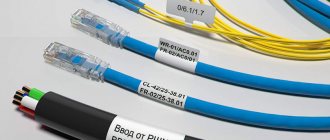
Thanks to this, tags with the following data appear on the insulation:
- cable brand;
- purpose;
- the object associated with it;
- line length and other information if necessary.
Cable tags greatly simplify such marking, making it convenient and as fast as possible. They are selected depending on the diameter, characteristics and insulating materials on the wire. They may differ in a number of parameters, but have a common purpose and are capable of storing inscriptions for long periods of use.
Requirements for inscriptions on tags
Pue-7 clause 2.3.122-2.3.133 laying cable lines in cable structures
Tags on the cable, secured with clamps or threaded through the wire, must be signed in a certain way; this rule is regulated by the rules of the PUE. In accordance with this document, the following data is applied to the label:
- Cable or line number. This is information that contains data about the direction of the highway, what it feeds, and what level of protection is required. During the wiring installation process, an object passport is drawn up, which indicates the buildings or premises powered by this line. They are assigned numbers, which will subsequently be written on the tag itself; during the service process, the technician will be able to look at the markings of the cables and, by comparing them with the object’s passport, understand where this or that line leads;
- Brand and cross-section of wire. Since space on the tag is limited, the designation is written abbreviated, with a minimum number of characters. For example, a vinyl-coated cable with a cross-section of 3*2.5 is briefly designated VVG-3/2.5;
- Line voltage. This is a mandatory parameter, since it is not clear from the outer sheath of the cables what voltage the current flows through it, respectively, and what level of protection is required during repair work;
- The beginning and end of cable lines. For more accurate information about possible losses on the main line after its installation, a designation of the total length is applied. After reading the data, the technician servicing the wire line will be able to accurately calculate the resistance and level of voltage loss in the network.
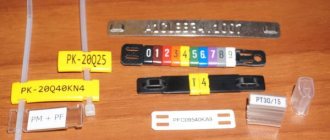
Labels on tags
All of the information listed is basic and mandatory. It is not prohibited to place additional information on the tag that characterizes the electrical main, for example, the date of laying. In addition, when placing a tag on the coupling, it is necessary to place the date of installation of the wire, since the coupling has its own resource, which will be calculated based on this indicator.
Inscriptions on metal tags are most often made by engraving with a special pencil or indelible paint. Plastic products are signed with a permanent marker or indelible paint. Also, when placing a tag using wire on a highway, it is necessary to additionally protect metal objects with bituminous composition or any other paint, otherwise the wire will rust and collapse, and the tag will be lost. Nylon thread is best suited for fastening; it is not afraid of temperature changes and high humidity.
Tag for threading onto wire
Recently, to indicate the cable on the line, many electricians began to use stickers that already have inscriptions informing about the voltage, as well as empty spaces in which additional data is written. Such stickers are very convenient, since the master does not waste time making markings, but simply glues the element onto the finished tag and continues installation.
Types of electrical communications devices
The Electrical Installation Rules (ELI) in the “Electrical Wiring” section describe methods for laying cables and wires.
Section PUE 2.1 “Electrical Wiring” specifies the rules for the installation of electrical wiring of power cables, lighting circuits and secondary DC and AC lines in rooms and along the facade of buildings and structures. These are installation wires in a PVC sheath of all sections, unarmored power lines with rubber or plastic coating in a sheath of metal, rubber or plastic. Electrical wiring comes in two types:
- open;
- hidden.
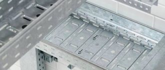
Open
Electric lines are laid on the surface of vertical and horizontal fences, supports and other building structures of buildings and structures. The wires are attached directly to the supporting surface, suspended on cables, rollers and insulators. Communications are hidden in pipes, trays, boxes, metalized shells, baseboards, fillets, etc.
Hidden
Conductors are laid inside the enclosing structures of premises: inside walls, ceilings, ceilings, placed in pipes, boxes or channels covered with plaster.
Important! Marking of cable and wire lines is carried out in open sections of routes. Hidden wiring must be marked under special conditions.
In accordance with the load on different sections of the power lines, the cross-section of the conductors is selected, which will prevent the wires from melting, otherwise this may cause a short circuit and ignition of the electrical wiring.
Main themes
Marking of cable lines (cable tags)
Cable tags
SNIP 3-05-06-85 “Electrical devices”, put into effect on July 1, 1986 (Resolution of the USSR State Construction Committee dated December 11, 1985 N 215)
P. 3.22. Wires and cables laid in boxes and on trays must be marked at the beginning and end of the trays and boxes, as well as at the points where they are connected to electrical equipment, and the cables, in addition, also at route turns and branches. Marking of cable lines P. 3.103. Each cable line must be marked and have its own number or name. P. 3.104. Labels must be installed on exposed cables and cable joints. On cables laid in cable structures, tags must be installed at least every 50 - 70 m, as well as in places where the direction of the route changes, on both sides of passages through interfloor ceilings, walls and partitions, in places where cables enter (exit) into trenches and cable structures. On hidden cables in pipes or blocks, tags should be installed at the end points at the end couplings, in the wells and chambers of the block sewer system, as well as at each connecting coupling. On hidden cables in trenches, tags are installed at the end points and at each coupling. P. 3.105. Tags should be used: in dry rooms - made of plastic, steel or aluminum; in damp rooms, outside buildings and in the ground - made of plastic. Designations on tags for underground cables and cables laid in rooms with a chemically active environment should be made by stamping, punching or burning. For cables laid in other conditions, markings may be applied with indelible paint. P. 3.106. Tags must be secured to the cables with nylon thread or galvanized steel wire with a diameter of 1 - 2 mm, or plastic tape with a button. The place where the tag is attached to the cable with wire and the wire itself in damp rooms, outside buildings and in the ground must be covered with bitumen to protect it from moisture.
Rules for the construction of electrical installations (PUE) clause 2.3.23. Each cable line must have its own number or name. If a cable line consists of several parallel cables, then each of them must have the same number with the addition of the letters A, B, C, etc. Openly laid cables, as well as all cable terminations, must be equipped with tags indicating the brand, voltage, cross-section, number or name of the line on the tags of the cables and terminations; on the coupling tags - coupling numbers and installation dates. Tags must be resistant to environmental influences. On cables laid in cable structures, tags must be located along the length at least every 50 m.
“Rules for technical operation of consumer electrical installations” (PTEEP) 2.4.5. Each CL must have a passport, including the documentation specified in clause 2.4.2. dispatch number or name. Openly laid cables, as well as all cable couplings, must be labeled; the cable tags at the beginning and end of the line must indicate the brand, voltage, cross-section, number or name of the line; on the coupling tags - coupling number, installation date. Tags must be resistant to environmental influences. They should be located along the length of the line every 50 m on openly laid cables, as well as at turns of the route and in places where cables pass through fire-resistant partitions and ceilings (on both sides).
Marking tags are manufactured in accordance with TU 36-1440-82: Round tag (U-135) – intended for power cables above 1000V; Square tag (U-134) – designed for power cables up to 1000V; Triangular tag (U-136) – designed for control cables.
Examples of cable tags:
In accordance with the operating rules for electrical installations, any cable line must have digital and/or letter designations. Often, when an electrical circuit includes several parallel conductors, a combined alphanumeric system is used. In such a situation, the cable tag of each core contains the same numerical value, but different letters of the Cyrillic or Latin alphabet.
The cable sleeve and exposed wires must be marked with tags indicating the number, line name, operating voltage, cross-sectional area and brand of electrical components used. All tags are characterized by resistance to negative environmental factors. The maximum allowable distance between tags is 50 m.
Basic requirements for marking wires in switchgears (switchgears) and switchboards
Clause 1.1.30 of the PUE states that all wires in the control panel must correspond to the alphabetic, digital and color designations. The presence of a color designation does not exclude the installation of numbers and letters. It is allowed to apply markings not along the entire length of the line, but only at the connection points.
Marking begins with compliance with the rules during the installation process, when connecting wires according to the color of the insulation. This is the most clear example, which allows operating personnel to quickly navigate the purpose of each individual wire in the circuit. Sometimes cables with wires of the same color are used; in these cases, it is possible to paint the ends of the wires, put on cambrics of the corresponding color, or it is more practical to install a heat-shrinkable tube with alphabetic and digital values already applied. The length of the marker tube must be at least 2.5 cm.
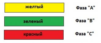
Wire marking by color
In three-phase networks, each phase is designated by the letters A, B, C, but in apartments and private houses single-phase power supply circuits are used, so there is no point in specifying which phase of the substation your panel is connected to.
Letter designations:
- The phase wire is marked with the letter “L”;
- The neutral wire is designated by the letter “N”;
- Grounding wires are marked with a symbol
- In circuits according to TN-CS system standards, it is allowed to connect the grounding conductor to the neutral wire. In such cases, “PEN” is written on the label.
- In DC power supply circuits, for individual consumer devices the polarities “+”, “-” and the voltage in volts “12V or 24V...” are indicated.
Marking DC circuits
Rules for placing tags on devices
What is PvS wire, its decoding, technical features and varieties
When installing in closed channels or collectors, the tags must be located in inspection wells, regardless of their distance from each other. The part is attached on both sides of the collector to each of the route branches. It is also necessary to mark the turning sections of the line on both sides, indicating the direction of rotation and degree.
When wiring passes through ceilings indoors or under the road surface, an inspection box must be installed, and the wires are marked with plastic tags.
When laying electric lines through undeveloped territory or lands intended for agriculture, markings are installed along the entire route in the form of poles with tags, which are also marked with the characteristics of the power line. Such poles will act as an object for reference to the terrain, their coordinates are included in the route plan, and if necessary, it will be possible to accurately determine the location of the cable under the ground.
Thus, according to the rules and regulations, all power installations and cable lines are subject to mandatory labeling, regardless of their voltage type and location. In addition, any qualified craftsman will agree to carry out repair work in an emergency area only if he has sufficient information about the characteristics of the electrical line.
Requirements for types and methods of attaching tags
In addition to the placement of tags, all information about the markings produced on cable lines and communication devices is recorded in a special journal. Such records are regularly updated depending on changes that have occurred in the network structure.
Ley Line Markers
In accordance with GOST, plastic plaques are made in square, round or triangular shapes. They are used in open areas of cable routes and circuit components. The tags have two holes through which the wire or core should be threaded, after which it is securely clamped and fixed in the desired position.
For lines whose voltage does not exceed 1000 V, square tags are used. If the operating voltage is above 1000 V, then round plastic plaques are used. Triangular products are required for control power lines.
Tags for low power circuits
For such purposes, small plates made of polymer materials can be used, which indicate information about the electricity consumption of the circuit subscriber and other data.
Main types of cable markers
A marking tag in accordance with international standards must be installed on open cable routes and power installations. If the wire is laid in structures specially designed for this purpose, then the distance between the markers can be 50-70 m. You cannot do without them in a number of other cases:
- when the route crosses various obstacles that make visual inspection difficult (interfloor ceilings, walls, partitions), then tags are placed on each side of the obstacle passed (for example, on both sides of the wall);
- at points where the direction of the cable line changes;
- in places where input or output from other structures is carried out.
Many manufacturers and electricians prefer cable tags made of plastic, since such material can withstand moisture for a long time without changing its properties.
Form of marking tags
The rules and regulations indicate information on the forms of tags, which were described above:
- triangular - installed in cable lines for control or signaling purposes;
- square – for power lines with voltage up to 1 kV;
- round – over 1 kV.
Label sizes
The most common brands of cable tags are U-134, U-135, U-136 and U-153. Let's compare their sizes and, depending on the data obtained, draw conclusions on possible use in systems:
- U-134 is used to mark power lines with voltages not exceeding 1000 V. The square tag with an area of 55x55 mm is equipped with two 11x3.5 mm grooves for fixing with a cable binder.
- U-135 is suitable for indicating information on electrical circuits with voltages over 1000 V. Round products with a diameter of 55 mm and similar grooves for cable binders.
- U-136 is used for marking signal and control wires. The triangular product has equal sides 62 mm long each. There are two slots for a cable binder of the same size.
- U-153 is used for power lines with voltages up to 1000 V. A square product with a length of 28 mm and a 5 mm hole is attached using a special wire.
Important! Many organizations either ignore the cable tagging process or perform it using free-form tags. The consequences of both decisions can cause frequent emergencies and injury to operating personnel.
Color coding of wires and cables
Generally accepted standards and rules for color marking the insulating sheath of wires allow you to quickly and accurately determine the operating parameters of a cable and understand in which systems and devices it can be used. The color marking regulations are prescribed by PUE and GOST.
It is noteworthy that the designation system will be different for cable networks with alternating current or direct current. Often the cable is made in different colors. Instead of a shell, color marking can be done using heat-shrinkable tubes (cambrics). Another option is colored electrical tape. The choice of color for phase and neutral wires should always be different!
For three-phase alternating power lines, the buses should be marked as follows:
- first phase – yellow;
- the second is green;
- the third is red.
In DC cable runs, color designations are chosen according to the charge, which can be positive or negative. In the first case, a wire with a red braid is selected, in the second, a wire with a blue braid. The system does not support phase and neutral wires, and for the middle wire a light blue conductor is usually used.
For power installations with voltage up to 1 kV and neutral, the following marking is carried out:
- working neutral wire – blue;
- grounding – yellow-green;
- combined zero – yellow-green with blue markers (or blue with yellow-green markers);
- phases - red, black and other colors depending on the quantity.
Read also: Reversing starter wiring diagram
It is noteworthy that the wiring inside electrical appliances is red, in sockets - brown.
The order of placement of conductors
When wiring multi-core lines proceed as follows. Wires are grouped into bundles, dividing them according to their intended purpose. A bundle of phase conductors is formed, neutral wires and grounding are assembled separately. If possible, the bundles are formed in even rows without interlacing. This will make it easier to find a particular wire.
In some cases, the phase and neutral wires that supply a specific consumer are placed in one bundle. Corresponding badges are attached to all bundles.
Cables in a switchboard or communication center are marked with tags to make it easy to find the desired line and determine its parameters.
Panel marking
Alphanumeric marking structure
Marking of wires and cables allows you to quickly find the desired wire among similar products that have the same type and color.
At large industrial facilities, where the number of installed communications is in the thousands, tags are used.
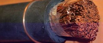
An experienced installer just needs to look at the markings and find out the size of the cross-section of the cores; cross-sectional area, which ranges from 0.35 to 70 square meters. mm; the number of cores and the metal from which they are made.
SIP wires are made from aluminum billets. The VVG cable, according to the marking, is made of copper wire.
Scheme of alphanumeric marking of power cables and wires
The cable marking contains information about the rated voltage for which the product is designed. The marking also contains information about the insulating material.
According to GOST, the list of such materials is strictly limited. Among the most well-known are rubber, paper, PVC and other plastics.
And one more important parameter that is important when choosing a cable is the material of the protective sheath. The outer shell is made of metal, plastic, rubber.
Tags with information about the purpose of the product are attached during the installation process. Deciphering the cable markings is inherently simple.
The initial letter in the marking code characterizes the metal from which the core is made. For aluminum conductors, the letter “A” is used. There are no letters for copper.
The same materials are used here, vinyl and rubber.
The fourth letter characterizes the cable design. “A” indicates that the cable is covered with an asphalt coating. "B" - armored with metal. “G” - has no protective cover or, as installers say, naked.
Why is marking needed?
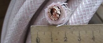
Even an experienced electrician or installer cannot accurately determine the diameter of the current-carrying conductor down to the millimeter by eye, because often a layer of insulating material carefully masks all visible differences.
Therefore, manufacturers apply markings along the entire length of the wire, which clearly shows:
- Number of cores;
- Core cross-section diameter;
- Insulation thickness;
- Material of core, insulation, gaskets;
- Conditions of transportation, storage, operation;
- Rated current load.
Markings are applied every ten centimeters in a color contrasting with the background in order to simplify and increase the safety of the electrical installation process as much as possible. It is a combination of seven to fifteen characters, letters and numbers. Color design is also used separately.
Knowing how to decipher the markings, you can accurately select the required cable, without relying on the experience of a store consultant or your own intuition.
Alphanumeric designations
GOST specifies regulations for marking the external insulation of cable lines, thanks to which cords, cables and wires can be distinguished from each other. If there are no markings on the braid or they are not sufficient for maintenance and safety, then special tags with additional data are attached to the route.
According to the rules and recommendations prescribed in GOST, a wire is a product consisting of one or more cores, which are protected with insulation along their entire length. The cores can be produced without insulation. A cable is defined as several conductors insulated separately from each other, placed under a single sealed sheath made of metal or polymer materials. A cord consists of two or more flexible conductors that are connected together by twisting or braiding. The cores are fixed along their entire length, and the braid is made from non-metallic materials.
All cables are divided into several groups:
- power;
- signaling and control;
- installation;
- radio frequency;
- connected.
You can decipher the alphanumeric symbols on the insulation yourself.
The first letter in the abbreviation indicates the material the core is made of. The letter “A” at the beginning indicates that the current-carrying conductor is made of aluminum. The absence of such a letter means that it is made of copper.
The second letter indicates the scope of application of the product. If the second letter in the abbreviation is missing, then such a cable is considered to be power.
The third letter is used to indicate the degree of flexibility of the product. Its absence indicates a single-core wire, the presence of the letter “G” indicates a flexible multi-core wire.
The fourth letter allows you to designate the material used to make the insulation. Windings are made from different materials, so more specific designations are used for it.
The fifth letter indicates the material used to make the outer shell and the presence or absence of an armored hull.
The sixth letter can be used to indicate the protective cover, the purpose of the layer and the structure as a whole.
What is a cable?
A cable is one or more insulated conductors enclosed in a common sealed sheath (lead, aluminum, rubber, plastic), on top of which, depending on the laying and operating conditions, there may be an armor sheath (coating of steel tapes or flat or round wire). Such cables are called armored. Cables without armor are used where there is no possibility of mechanical damage.
According to the area of application, the cables are divided into the following types:
- Power cables are designed for the transmission and distribution of electrical energy in lighting and power electrical installations to create cable lines. They are produced with copper and aluminum conductors with insulation made of paper, PVC, polyethylene, rubber and other materials, and have lead, aluminum, rubber or plastic protective sheaths.
- Control cables are used to power various electrical devices with low voltage signals and create control circuits. They can have copper or aluminum conductors with a cross-section from 0.75 to 10mm2.
- Control cables are used in automation systems and usually have copper conductors, a plastic sheath and a protective shield that protects against mechanical damage and electromagnetic interference.
- RF cables are used to provide communication between radio devices. They have a coaxial design with a central copper core, which has insulation made of polyethylene or polyethylene, on top of the insulation there is an outer conductor and a sheath of PVC or polyethylene.
Common labeling mistakes
Let's list three main mistakes:
- The most common one is caused by novice electricians or experienced specialists due to inattention. In the process of screwing the wire to the shield and terminals, the craftsmen simply forget to put a heat-shrinkable tube with markings (tube) on the wires. Because of this, you have to unscrew the attached wiring and put the products on again.
- Often craftsmen confuse the PEN conductor with a grounding cable. The fact is that both elements have identical color markings, so you need to inspect them more carefully.
- If the panel is located outside the site, then it is necessary to conclude an agreement with the electrical energy supplier. You must have on hand technical documentation with a diagram and confirmation of compliance with the requirements of the PUE, PTEEP and other regulatory acts. Otherwise, you may face claims from Rostekhnadzor.
Qualified specialists will agree to carry out repair work and engage in maintenance of emergency areas only if sufficient information about the parameters of the line is provided. This is exactly what is contained on the cable tags.
To properly install and operate electrical wiring and other devices, you must have at least minimal knowledge of the standards for cable lines and electrical installations. There are many provisions and instructions governing the actions of an electrician and installer when working on electrical lines of various voltages. Such documents also include the Rules for marking wires on the main line and in the distribution cabinet. This article discusses the types of tags for cable markings, as well as the conditions under which the label should be on the surface of the wire.
Cable tags
Types of markings
All information about the characteristics of the wire is indicated in three ways:
- Color;
- With Latin letters;
- Arabic numerals.
All methods and types of markings are included in GOST and other domestic and international documents regulating construction standards. Therefore, every electrician needs to know the basic rules for marking.
Option 1 - Color marking
The most obvious and simplest is the color marking of the cable, which determines the type of supporting wire:
- Zero - blue, cyan and their shades.
- Grounding - green, yellow or green-yellow combination.
- Phase - red, orange, pink and white tones are more common, but in general the phase can be any except the shades mentioned above.
Color designation is paramount, since many accidents and short circuits occur precisely because of incorrect connection of paired conductors.
Knowing the basic colors allows you to simplify the installation process and protect your life, the health of loved ones and personal property.
Option 2 - Letters and letter combinations
In the case of letters, everything is much more complicated. They indicate the materials used in the manufacture and the operating features of the cables. The sequence is important:
The first letter indicates the material of the core. There are only two options: “A” - aluminum or none - copper.
The second characterizes the purpose of the wire. For example, “K” - control, “P” - flat, “M” - assembly. The full list can be found in the table below.
The third letter is the marking of the core insulation, which can be made from polyvinyl chloride (PV), nylon (K), rubber (R), nayrite (N), polyethylene (P), the addition of enamel (ME), silk (O), fiberglass ( ABOUT).
Electrical wiring in a house or cottage serves to transport electricity to various types of electricity consumers: lighting fixtures, heaters, boilers, pumps, televisions, etc. All these devices create comfortable living conditions and have a wide range of power consumption from 10 W (shavers, DVDs) to 5 kW (boilers, electric boilers). The role of electrical wires is very difficult to overestimate. Further comfort and safety during operation depends on the correct choice of wire types for various consumer groups at the design and construction stage. Hundreds of meters of wires for various purposes are hidden in the walls of modern buildings, and they are all different - some are thicker, others are thinner, some have two cores, and some have three or more. Each wire has its own purpose (power wiring, lighting, signal cables, telephone cables, Internet) and is responsible for the operation of a particular electrical appliance. Of the many different types of wires and cables, in this article we will look at electrical wires and cables used in construction to transport electricity. Let's consider their varieties, brands and scope of application. Electrical wiring – consists of wires and cables with their associated fastenings, support and protective structures.
Electrical wires are produced in copper and aluminum. Copper wires have better conductivity than aluminum wires, but are also more expensive.
How to mark
The most reliable method of marking cable lines is stamping. On the other hand, this method requires the presence of special equipment (a printer), which cannot always be used.
In many ways, the choice of a specific method depends on the material used to make the cable tag. You can also buy markers with already prepared symbols, sold in ribbons. They have cuts that allow you to quickly and accurately remove the desired label and fix it on the wire using an adhesive surface.
The inscriptions are made from waterproof paint or ink. If the electrical circuit is installed in rooms with high humidity levels or is constantly exposed to an aggressive environment, then the marking is applied by milling, punching, burning or stamping on plastic/metal.
For dry rooms with good ventilation or air conditioning, you can get by with marking using standard means - a pencil or felt-tip pen.
How to check and buy a reliable fire alarm cable?
Which fire alarm cable is best for you depends on many factors. The basis for the choice is the PUE standards, the requirements of GOSTs and NPB (fire safety standards).
A cable can only be reliably tested for compliance with all fire safety standards in specialized laboratories, but if you need an express test, just try setting a small sample of the cable on fire. The cable should extinguish without flame and not emit black smoke when burning. The video below is an example of such an express check.
| Employees of the Cable Systems company are ready to advise on all the necessary parameters of the required brand of cable for a fire alarm by calling 8 (800) 555-88-72 or online |
Types of tags
Branding of wires is carried out using factory-made or self-made tags. But their form must strictly comply within certain standards.
These standards determine the types of labels used to mark cable lines. The following forms of these products exist:
Square
. They designate power lines up to 1000 V. As a rule, these are lines for household use.
Round
. They are used to show wires through which voltages exceeding 1000 V are supplied. Such lines are classified as industrial, which require a high degree of safety during installation and use.
Triangular
. They are used to mark low-voltage wires. It is made in the shape of an equilateral triangle.
Photos of cable markings
- Wire connector: instructions on how to make the connection yourself. Instructions for use of clamp, clamp and lugs
Wire lugs: instructions on how to select and install a lug. Overview of all types, photos, instructions, diagrams
Heat shrink for wires: all types and characteristics. Detailed description of how to choose and use heat shrink
Read here! Wiring in a wooden house - design, installation and basic safety requirements (120 photos)