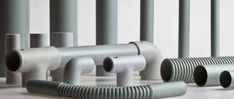
Basic Concepts
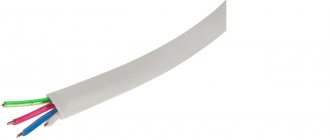
A wire is understood as a single or multi-core structure, which can be bare (without insulation) or braided with rubber or plastic. Examples of the use of wires are motor windings, parts of radio equipment and power lines.
A cable is an assembly of one or more insulated cores having a single shell. To protect against damage, armor is placed on top.
Where is it used?
Copper wires are used to transmit electricity. They have excellent performance properties and a wide load range (60-600 V), which is why they are gradually replacing their aluminum counterpart. Product classification:
- power. They transmit current from stations to substations, industrial facilities, and utilities. Insulated with paper, rubber and plastic. There are armored cables coated with lead or aluminum;
- household They connect various electrical appliances to the network. Single or multi-core wiring;
- control. They connect electrical devices and distribution mechanisms. Allowed for installation indoors and outdoors;
- special. Signals are transmitted through them. These are high- and low-frequency products (the former are used for long-distance communications).
Note! Most often, copper wires are used to lay power lines. They have high fire safety, therefore they are in demand for enterprises where the risk of fire or explosion is high. They are used no less often in residential and public buildings.
You might be interested in this: Features of the SIP-2 cable
Flexible copper cables, also called control cables, are insulated with a rubber layer. Thanks to this, they can be used for laying even under harsh climate conditions. To improve performance, the insulation is diluted with special components.
Armored cables with double insulation are used when laying networks through tunnels, routes, air or in the ground. Graphite chips are added to their outer layer, which increases the product’s resistance to mechanical damage and fire.
These wires carry current into the house.
Advantages of copper conductors
It is not without reason that copper is chosen as a raw material for the manufacture of cable products. Compared to aluminum, it has a number of advantages:
- The resistance of copper wires is lower than that of aluminum. This allows the use of a smaller cross-sectional diameter and reduces heating losses.
- Good corrosion resistance. Complete replacement of supply networks is carried out after 30-35 years of operation.
- Plastic. Copper wire is very flexible, which makes the installation process easier and eliminates kinks.
Insulation layer
It is no secret that the insulation of copper wires prevents human contact with a potentially dangerous current-carrying circuit. Another role is to prevent short circuits between adjacent phases.
The manufacturing material is subject to strict requirements for withstanding voltage, temperatures, UV radiation, and mechanical properties. Most often used:
- PVC. It is characterized by low cost, wear resistance, and satisfactory chemical resistance. The downside is the release of harmful gases when overheated.
- Rubber. Characterized by increased flexibility and resistance to negative temperatures.
- Polyethylene. It has excellent dielectric properties, but not as good flexibility as the first two materials.
- Carbolite. A distinctive feature is heat resistance combined with sufficient ductility.
Section calculation
The cross-section of a copper wire is the area that the core has in cross section. The value is influenced by the long-term permissible load and current strength.
The easiest way to calculate the cross-section is to use data from tables that take into account operating conditions and maximum current. To do this, you will need two more indicators - the total power of electrical consumers (kW or W) and voltage (V). The first is indicated in technical data sheets or on the housings of devices, and the second for city apartments is 220 V.
Next, the obtained power values are found in special tables and compared with the diameter of the conductor. Remember that in calculations it is necessary to leave a small margin in diameter. After all, when connecting new equipment, the load will increase.
NON-INSULATED WIRES FOR OVERHEAD POWER LINES AND ELECTRIFIED TRANSPORT
2.1. NOMENCLATURE
Non-insulated wires for overhead lines are intended for the transmission of electrical energy in overhead electrical networks and electrified transport lines. Under operating conditions, these wires are insulated from the ground and from each other using porcelain, glass and other insulators on which they are suspended. The distance between the wires is selected depending on the transmitted voltage. Split two to four wires are under the same voltage and are suspended on one garland of pendant insulators. The list of brands of bare wires for power lines and contact wires for electrified transport is given in Table. 2.1, and the assortment is in table. 2.2.
Table 2.1. Nomenclature of bare wires
| Brand | OKP code | The wire | GOST, TU |
| Wires for overhead power lines | |||
| A | 3511410100 | Twisted from aluminum AT wires | GOST 839-80 |
| automatic transmission | 3511410200 | The same, but the interwire space, with the exception of the outer surface, is filled with neutral lubricant with increased heat resistance | Same |
| Up | 3511410300 | Twisted from aluminum wires ATp | ” |
| ApKP | 3511410500 | The same, but the interwire space, with the exception of the outer surface, is filled with neutral lubricant with increased heat resistance | ” |
| AJ | 3511910100 | Twisted from wires of heat-treated aluminum alloy ABE | ” |
| AZHKP | 3511910400 | The same, but the interwire space, with the exception of the outer surface, is filled with neutral lubricant with increased heat resistance | ” |
| AN | 3511910200 | Twisted from wires of non-heat-treated aluminum alloy ABE | ” |
| ANCP | 3511910300 | The same, but the interwire space, with the exception of the outer surface, is filled with neutral lubricant with increased heat resistance | ” |
| AC | 3511510100 | Consists of a steel core and aluminum wires AT | ” |
| ASKS | 3511510400 | The same, but the interwire space of the steel core is filled with a neutral lubricant of increased heat resistance | ” |
| ASK | 3511510200 | The same, but the steel core is insulated with two PET tapes | ” |
| ASKP | 3511510300 | The same as the AC brand, but the interwire space of the entire wire, with the exception of the outer surface, is filled with neutral grease with increased heat resistance | ” |
| ApS | 3511510700 | Consists of a steel core and aluminum wires ATP | ” |
| ApSKS | 3511511000 | The same, but the interwire space of the steel core is filled with a neutral lubricant of increased heat resistance | ” |
| ApSC | 3511510800 | The same, but the steel core is insulated with two PET tapes | ” |
| ApSKP | 3511510900 | The same as the ApS brand, but the interwire space of the entire wire, with the exception of the outer surface, is filled with neutral lubricant of increased heat resistance | ” |
| M | 3511110100 | One or more stranded copper wires | ” |
| B | 3511630100 | Twisted from bronze wires | TU 16.501.017-74 |
| BS | 3511730100 | Consists of a steel core and bronze wires | Same |
| PS | 1265000100 | Twisted from galvanized steel wires | TU 14.4.661-75 |
| PA | 3511440400 | Aluminum hollow | TU 16.505.397-72 |
| PM | 3511140200 | Copper hollow | Same |
| Contact wires | |||
| BrF | 3513630300 | Bronze shaped | GOST 2584-75 |
| BrFO | 3513631000 | Same oval | Same |
| MK | 3513120100 | Copper round | ” |
| MF | 3513130200 | Same shaped | ” |
| MFO | 3513130300 | Same oval | ” |
| NLF | 3513700100 | Low alloy copper, shaped | ” |
| NLFO | 3513700200 | Same oval | ” |
| PKSA | 1264000100 | Steel-aluminum | TU 14.4.419-73 |
Table 2.2. Assortment of bare wires
| Wire brand | S, mm2 |
| A, AKP, Ap, ApKP | 16, 25, 35, 50, 70, 95, 120, 150, 185, 240, 300, 350, 400, 450, 500, 550, 600, 650, 700, 750, 800 |
| ApS, ApSK, ASKP, ApSKP, ApSKS, AS, ASK, ASKS | 10, 16, 25, 35, 50, 70, 95, 120, 150, 185, 205, 240, 300, 330, 400, 450, 500, 550, 600, 650, 700, 750, 800, 1000 |
| AZH, AN, AZHKP, ANKP | 16, 25, 35, 50, 120, 150, 185 |
| B | 50, 70, 95, 120, 150, 185, 240, 300 |
| BS | 185, 240, 300, 400 |
| M | 4, 6, 10, 16, 25, 35, 50, 70, 95, 120, 150, 185, 240, 300, 350, 400 |
| BrFO, MK, MFO | 30, 40, 50, 65, 85, 100 |
| BrF, MF, NLF | 65, 85, 100, 120, 150 |
| BrFO, MFO, NLFO | 100, 120, 150 |
| PA | 500, 640 |
| PKSA | 80/180 |
| PM | 240, 300 |
| PS | 25, 35, 50, 70 |
| Notes: 1. For wires ApS, ApSK, ApSKP, ApSKS, AS, ASK, ASKP and ASKS, cross-sections are indicated only for layers of aluminum wires. 2. Numerator is the cross-section of copper wire equivalent in conductivity, denominator is the total cross-section of steel-aluminum wire. | |
2.2. ALUMINUM WIRES
Aluminum wires for power lines of grades A, Ap and AKP are twisted in concentric layers in alternating directions from AT aluminum wires, and wires of grades Ap and ApKP are twisted from ATp wires in accordance with GOST 6132-79. The outer heave has a right direction. The appearance of aluminum wires of grades A and AKP is shown in Fig. 2.1. In wires of the AKP and ApKP brands, the gaps between the wires (with the exception of the outer layer) are filled with a neutral lubricant of increased heat resistance. The design data of aluminum wires, weight, resistance R over a length of 1 km at 20ºC, tensile failure load and wire length are given in table. 2.3. Wire connections in a single-wire core are not permitted. In wires with more than seven wires, it is allowed to connect them in all layers. The splicing of wires is carried out in rapid succession, the distance between the places of welding of different wires or the same wire is at least 15 m.
The place where the wires are welded is annealed at a distance of no more than 0.2 m in both directions. The conversion factor of the mass of aluminum wires to the mass of copper wires is 2.
The predominant area of application of aluminum wires A and AP in the air atmosphere of types I and II, subject to a sulfur dioxide content of no more than 150 mg/(m2H day) (1.5 mg/m3) on land in all macroclimatic regions according to GOST 15150-69, except for TV and vehicles , and AKP and AKP wires - on the coasts of seas, salt lakes, in industrial areas and areas of saline sand, as well as in adjacent areas with an air atmosphere of types II and III, on land and at sea in all macroclimatic regions according to GOST 15150-69 . The service life of wires A and AP is at least 45 years, and the wires of AKP and APKP are at least 25 years.
Figure 2.1. Bare wires A and automatic transmission
Table 2.3. Design data and parameters of aluminum wires A, AKP, Ap and ApKP
| S, mm2 | n*d, mm | D, mm | g, kg/km | Breaking tensile load, kN | Wire length, m, not less | |||
| aluminum in wires | lubricants in automatic transmission, automatic transmission | R, Ohm, no more | from wire AT | from wire ATp | ||||
| 16 | 7*1,70 | 5,1 | 43 | 0,5 | 1,8376 | — | 2,9 | 4500 |
| 25 | 7*2,13 | 6,4 | 68 | 0,5 | 1,1650 | — | 4,3 | 4000 |
| 35 | 7*2,50 | 7,5 | 94 | 0,5 | 0,8502 | — | 5,9 | 4000 |
| 50 | 7*3,00 | 9,0 | 135 | 0,5 | 0,5880 | 7,6 | 8,2 | 3500 |
| 70 | 7*3,55 | 10,7 | 189 | 1,0 | 0,4204 | 10,64 | 11,3 | 2500 |
| 95 | 7*4,10 | 12,3 | 252 | 1,0 | 0,3147 | 13,77 | 14,6 | 2000 |
| 120 | 19*2,80 | 14,0 | 321 | 16 | 0,2510 | 17,97 | 19,6 | 1500 |
| 150 | 19*3,15 | 15,8 | 406 | 20 | 0,1978 | 22,75 | 24,1 | 1250 |
| 185 | 19*3,50 | 17,5 | 502 | 25 | 0,1611 | 28,12 | 29,8 | 1000 |
| 240 | 19*4,00 | 20,0 | 655 | 33 | 0,1230 | 36,68 | 37,8 | 1000 |
| 300 | 37*3,15 | 22,1 | 794 | 54 | 0,1017 | 44,27 | 46,9 | 1000 |
| 350 | 37*3,45 | 24,2 | 952 | 65 | 0,0848 | 53,2 | 56,4 | 1000 |
| 400 | 37*3,66 | 25,6 | 1072 | 73 | 0,0756 | 59,8 | 63,4 | 1000 |
| 450 | 37*3,90 | 27,3 | 1271 | 84 | 0,0666 | 67,94 | 69,8 | 1000 |
| 500 | 37*4,15 | 29,1 | 1378 | 94 | 0,0588 | 74,53 | 79,2 | 1000 |
| 550 | 61*3,37 | 30,3 | 1500 | 117 | 0,0540 | 83,59 | 88,7 | 1000 |
| 600 | 61*3,50 | 31,5 | 1618 | 126 | 0,0503 | 90,2 | 95,6 | 800 |
| 650 | 61*3,66 | 32,9 | 1771 | 138 | 0,0459 | 98,6 | 104,6 | 800 |
| 700 | 61*3,80 | 34,2 | 1902 | 149 | 0,0425 | 106,3 | 112,7 | 800 |
| 750 | 61*3,95 | 35,6 | 2062 | 161 | 0,0393 | 114,9 | 118,3 | 800 |
| 800 | 61*4,10 | 36,9 | 6160 | 173 | 0,0365 | 120,0 | 127,5 | 800 |
2.3. ALUMINUM ALLOY WIRES
Wires made of aluminum alloy ABE (0.3-0.5% magnesium, 0.4-0.7% silicon and 0.2-0.3% iron) are twisted from AST grade wire, which has a breaking tensile stress before twisting in wire of at least 0.24 kN and elongation of at least 1.5%. Heat-treated ASZ grade wire has a tensile failure stress of at least 0.3 kN and a relative elongation of at least 4.0%. The electrical resistivity at 20ºC of AST grade wire is no more than 3.0*108 Ohm*m, and ASZ grade wire is no more than 3.25*108 Ohm*m. Bare wires of the AZh and AZHKP grades are made from heat-treated wire of the AST grade, and the AN and ANKP grades are made from non-heat-treated wire of the ASZ grade. The wire is twisted in layers in alternating directions, the outer layer is in the right direction. The connection of wires in wires twisted from seven wires is not allowed. In wires with more than seven wires, it is allowed to connect the wires in all layers. The splicing of wires is carried out at speed, the distance between the places of welding of different wires or the same wire is at least 15 m. The place of welding of wires is annealed at a distance of 0.2 m in both directions. In AZhKP and AHKP wires, the space between the wires (with the exception of the outer layer) is filled with a neutral lubricant of increased heat resistance. Structural dimensions, weight, electrical resistance, temporary resistance and length of wires AZH, AZHKP, AN and ANKP are given in table. 2.4.
The predominant area of application of AZh and AN wires in the air atmosphere of types Ι and II, provided that the sulfur dioxide content is not more than 150 mg/(m2*day) (1.5 mg/m3) on land in all macroclimatic regions according to GOST 15150-69, except for TV and vehicles, and AZhKP and AHKP wires - on the coasts of seas, salt lakes, in industrial areas and areas of saline sand, as well as in adjacent areas with an air atmosphere of types II and III, on land and sea of all macroclimatic regions according to GOST 15150- 69.
The service life of wires AZH, AZHKP, AN and ANKP is at least 25 years.
Table 2.4. Design data and parameters of wires AZH, AZHKP, AN and ANKP made of aluminum alloy
| S, mm2 | n*d, mm | D, mm | g, kg/km | R, Ohm, no more | Breaking tensile load, kN, not less | Wire length, m, not less | |||
| without lubrication | lubricant | AZHKP | AN, ANKP | AZHKP | AN, ANKP | ||||
| 16 | 7*1,70 | 5,1 | 43,0 | 0,5 | 2,1130 | 1,9505 | 4,66 | 3,55 | 4500 |
| 25 | 7*2,13 | 6,4 | 68,0 | 0,5 | 1,3396 | 1,2365 | 6,97 | 5,11 | 4000 |
| 35 | 7*2,50 | 7,5 | 94,0 | 0,5 | 0,9775 | 0,9023 | 9,60 | 7,03 | 4000 |
| 50 | 7*3,00 | 9,0 | 135,0 | 0,5 | 0,6761 | 0,6241 | 13,83 | 10,14 | 3500 |
| 120 | 19*2,80 | 14,0 | 321,0 | 16 | 0,2836 | 0,2664 | 32,69 | 23,97 | 1500 |
| 150 | 19*3,15 | 15,8 | 406,0 | 20 | 0,2289 | 0,2113 | 41,36 | 30,31 | 1250 |
| 185 | 19*3,50 | 17,5 | 502,0 | 25 | 0,1850 | 0,1707 | 51,06 | 37,45 | 1000 |
2.4. ALUMINUM STEEL WIRES
Steel-aluminum wires consist of a steel core of twisted aluminum wires. The core of steel-aluminum wires is twisted from galvanized steel wires in accordance with GOST 9850-72. On top of the steel core in steel-aluminum wires of the AS, ASK, ASKP and ASKS brands, strands of AT aluminum wire are applied in alternating directions, and in wires of the ApS, ApSK, ApSKP and ApSKS brands, strands of ATp wires are applied in accordance with GOST 6132-79. The outer heave has a right direction. The connection of solid core wire is not allowed. In wires with more than seven wires, connections are allowed in all layers. The splicing of wires is carried out at speed, the distance between the places of welding of different wires or the same wire is at least 15 m. The place of welding of wires is annealed at a distance of no more than 0.2 m in both directions. The appearance of the AC and ApS wires is shown in Fig. 2.2. In ApSKP, ApSKS, ASKP and ASKS wires, the gaps between the galvanized steel wires of the core are filled with a neutral lubricant of increased heat resistance, and in ApSK and ASK wires, the steel core is wrapped or covered longitudinally with one or two strips of PET (lavsan) film. Design data of wires ApS, ApSK, ApSKP, ApSKS, AS, ASK, ASKP and ASKS, weight, conversion factor of the mass of steel-aluminum wires to the mass of copper wires (used when planning non-insulated wires), tensile failure load, electrical resistance over a length of 1 km and The lengths of the supplied wires are given in table. 2.5. In the marking of the cross-section of steel-aluminum wires, the cross-section of aluminum wires is given in the numerator, and the cross-section of galvanized steel wires is given in the denominator.
The predominant area of application for APS and AS wires is in air types I and II, provided that the sulfur dioxide content in the atmosphere is no more than 150 mg/(m2*day) (1.5 mg/m3, on land in all macroclimatic regions according to GOST 15150-69 , except for vehicles and TV; wires ApSK, ASK, ApSKS and ASKS - on the coasts of seas, salt lakes, in industrial areas and areas of saline sand, as well as in adjacent areas with an air atmosphere of types II and III, provided that the atmosphere contains sulfur dioxide gas no more than 150 mg/ (m>2*day) (1.5 mg/m3 and chloride salts no more than 200 mg/ (m2*day) on land in all macroclimatic regions according to GOST 15150-69, except for TV; ApSKP wires and ASCP on the coasts of seas, salt lakes, in industrial areas and areas of saline sand, as well as in adjacent areas with an air atmosphere of types II and III on land and at sea in all macroclimatic regions according to GOST 15150-69.
The service life of AS and ApS wires is at least 45 years, ApSKP and ASKP wires are at least 25 years, and ApSK, ApSKS, ASK and ASKS wires are at least 10 years.
Figure 2.2. Bare AC Wire
Table 2.5. Design data of steel-aluminum wires of the brands ApS, ApSK, ApSKP, ApSKS, ApSKS, AS, ASK, ASKP, ASKS
| S*, mm2 | n*d, mm | D, mm | Coefficient of conversion of natural mass to copper mass | g, kg/km | Breaking tensile load, kN, not less | R, Ohm, no more | Wire length, m, not less | ||||||
| steel | aluminum | aluminum parts of all brands | AS, ApS | ASK, ApSK | ASKP, ApSKP | ASKS, ApSKS | AT | ATp | |||||
| 1*1,50 | 6*1,50 | 4,5 | 1,36 | 28,9 | 42,7 | 43,26 | 43,7 | 43,7 | — | 4,09 | 2,7663 | 3000 | |
| 1*1,85 | 6*1,85 | 5,6 | 1,36 | 44,0 | 64,9 | 65,46 | 65,9 | 65,9 | — | 6,22 | 1,800934 | 3000 | |
| 1*2,30 | 6*2,30 | 6,9 | 1,36 | 67,9 | 100,3 | 100,86 | 101,8 | 101,8 | — | 9,3 | 1,1759 | 3000 | |
| 1*2,80 | 6*2,80 | 8,4 | 1,36 | 100,0 | 148,0 | 148,84 | 150,5 | 150,5 | — | 13,5 | 0,7897 | 3000 | |
| 1*3,20 | 6*3,20 | 9,6 | 1,36 | 132,0 | 195,0 | 195,84 | 198 | 198 | 16,64 | 17,11 | 0,60298 | 3000 | |
| 1*3,80 | 6*3,80 | 11,4 | 1,36 | 188,0 | 276,0 | 278,12 | 300,5 | 300,5 | 23,47 | 24,13 | 0,42859 | 2000 | |
| 19*2,20 | 18*2,20 | 15,4 | 2,0 | 188,0 | 755,0 | 777,0 | 793 | 793 | — | 96,83 | 0,42760 | 2000 | |
| 1*4,50 | 6*4,50 | 13,5 | 1,36 | 261,0 | 385,0 | 386,4 | 391 | 391 | 32,43 | 33,37 | 0,30599 | 1500 | |
| 37*2,20 | 24*2,20 | 19,8 | 2,0 | 251,0 | 1357,0 | 1387 | 1420 | 1426 | — | 180,78 | 0,32108 | 1500 | |
| 7*1,85 | 26*2,40 | 15,2 | 1,38 | 324,0 | 471,0 | 482 | 506 | 482 | — | 41,52 | 0,24917 | 2000 | |
| 7*2,20 | 30*2,20 | 15,4 | 1,22 | 320,0 | 528, | 542 | 565 | 542 | — | 49,47 | 0,25293 | 2000 | |
| 7*1,85 | 24*2,80 | 16,8 | 1,48 | 407,0 | 554,0 | 565 | 596 | 566 | — | 46,31 | 0,19919 | 2000 | |
| 7*2,10 | 26*2,70 | 17,1 | 1,37 | 409,0 | 599,0 | 612 | 643 | 613 | — | 52,28 | 0,19798 | 2000 | |
| 7*2,50 | 30*2,50 | 17,5 | 1,21 | 406,0 | 675,0 | 692 | 723 | 693 | — | 62,64 | 0,20065 | 2000 | |
| 7*2,10 | 24*3,15 | 18,9 | 1,47 | 515,0 | 705 | 718 | 758 | 719 | 56,24 | 58,08 | 0,15701 | 2000 | |
| 7*2,30 | 26*2,98 | 18,8 | 1,38 | 500,0 | 728 | 743 | 780 | 744 | 59,63 | 62,06 | 0,16218 | 2000 | |
| 7*2,80 | 30*2,80 | 19,6 | 1,21 | 509,0 | 846 | 866 | 907 | 869 | — | 77,77 | 0,15762 | 2000 | |
| 37*2,10 | 54*2,10 | 23,1 | 2,0 | 517,0 | 1525 | 1552 | 1626 | 1588 | — | 183,82 | 0,15762 | 2000 | |
| 7*2,20 | 24*3,30 | 19,8 | 1,47 | 566,0 | 774 | 788 | 831 | 789 | 61,73 | 63,74 | 0,14294 | 2000 | |
| 7*2,40 | 24*3,60 | 21,6 | 1,47 | 673,0 | 921 | 937 | 987 | 938 | 72,66 | 75,05 | 0,12060 | 2000 | |
| 7*2,65 | 26*3,40 | 21,6 | 1,37 | 650,0 | 952 | 970 | 1023 | 974 | 78,58 | 80,90 | 0,12428 | 2000 | |
| 7*3,20 | 30*3,20 | 22,4 | 1,21 | 665,0 | 1106 | 1131 | 1184 | 1136 | 95,89 | 98,25 | 0,12182 | 2000 | |
| 7*2,65 | 24*4,00 | 24,0 | 1,47 | 830,0 | 1132 | 1150 | 1219 | 1154 | 89,16 | 90,57 | 0,09747 | 2000 | |
| 7*2,95 | 26*3,80 | 24,1 | 1,37 | 812,0 | 1186 | 1208 | 1273 | 1213 | 97,76 | 100,62 | 0,09983 | 2000 | |
| 19*2,10 | 30*3,50 | 24,5 | 1,22 | 796,0 | 1313 | 1333 | 1408 | 1350 | 123,44 | 126,3 | 0,10266 | 2000 | |
| 7*3,50 | 30*3,50 | 24,5 | 1,21 | 796,0 | 1323 | 1343 | 1418 | 1360 | 114,70 | 117,52 | 0,10266 | 2000 | |
| 37*2,65 | 54*2,65 | 29,2 | 2,0 | 823,0 | 2428 | 2467 | 2578 | 2530 | — | 284,58 | 0,09934 | 2000 | |
| 7*2,30 | 48*2,98 | 24,8 | 1,6 | 924,0 | 1152 | 1166 | 1264 | 1168 | 84,56 | 88,85 | 0,08799 | 2000 | |
| 7*2,80 | 54*2,80 | 25,2 | 1,47 | 918,0 | 1255 | 1276 | 1368 | 1278 | — | 103,80 | 0,08888 | 2000 | |
| 7*1,85 | 42*3,40 | 26,0 | 1,73 | 1052,0 | 1199 | 1211 | 1330 | 1211 | 81,86 | 85,6 | 0,07752 | 1500 | |
| 7*2,00 | 76*2,57 | 26,6 | 1,73 | 1089,0 | 1261 | 1273 | 1396 | 1273 | — | 95,12 | 0,07501 | 1500 | |
| 7*3,05 | 54*3,05 | 27,5 | 1,47 | 1090,0 | 1490 | 1514 | 1624 | 1518 | 115,40 | 120,48 | 0,07477 | 1500 | |
| 7*3,40 | 26*4,37 | 27,7 | 1,37 | 1074,0 | 1572 | 1600 | 1707 | 1607 | 125,37 | 129,18 | 0,07528 | 1500 | |
| 19*2,50 | 30*4,15 | 29,1 | 1,21 | 1119,0 | 1851 | 1878 | 2000 | 1904 | 169,74 | 173,72 | 0,07247 | 1500 | |
| 7*3,20 | 54*3,20 | 28,8 | 1,47 | 1199,0 | 1640 | 1665 | 1785 | 1670 | 127,11 | 131,37 | 0,06786 | 1500 | |
| 7*2,20 | 42*3,90 | 30,0 | 1,73 | 1384,0 | 1592 | 1606 | 1750 | 1607 | 107,28 | 112,19 | 0,05877 | 1500 | |
| 7*2,20 | 76*2,84 | 29,4 | 1,74 | 1329,0 | 1537 | 1551 | 1689 | 1552 | 106,40 | 112,55 | 0,06129 | 1500 | |
| 7*3,40 | 54*3,40 | 30,6 | 1,47 | 1354,0 | 1852 | 1880 | 2015 | 1885 | 143,45 | 148,26 | 0,06040 | 1500 | |
| 37*2,65 | 90*2,65 | 34,5 | 2,0 | 1374,0 | 2979 | 3002 | 3209 | 3084 | 312,31 | 319,61 | 0,06025 | 1500 | |
| 61*2,65 | 54*3,40 | 37,5 | 2,0 | 1355,0 | 4005 | 4054 | 4275 | 4173 | 461,83 | 466,65 | 0,06040 | 1500 | |
| 7*3,60 | 54*3,60 | 32,4 | 1,47 | 1518,0 | 2076 | 2106 | 2260 | 2114 | 160,78 | 166,16 | 0,05381 | 1200 | |
| 19*2,20 | 54*3,70 | 33,2 | 1,48 | 1603,0 | 2170 | 2192 | 2364 | 2209 | 178,15 | 183,84 | 0,05091 | 1200 | |
| 19*2,30 | 96*2,90 | 34,7 | 1,48 | 1752,0 | 2372 | 2395 | 2602 | 2414 | 192,37 | 200,45 | 0,04655 | 1000 | |
| 19*2,40 | 96*3,02 | 36,2 | 1,48 | 1900,0 | 2575 | 2599 | 2828 | 2621 | 209,01 | 217,78 | 0,04289 | 1000 | |
| 19*2,50 | 96*3,15 | 37,7 | 1,48 | 2068,0 | 2800 | 2827 | 3072 | 2849 | 227,11 | 234,45 | 0,03939 | 1000 | |
| 19*2,65 | 96*3,30 | 39,7 | 1,48 | 2269,0 | 3092 | 3121 | 3402 | 3149 | 252,02 | 260,07 | 0,03586 | 1000 | |
| 7*3,20 | 76*4,10 | 42,4 | 1,48 | 2769,0 | 3210 | 3235 | 3565 | 3240 | 214,21 | 224,05 | 0,02936 | 1000 | |
2.5. COPPER WIRES
Copper wires grade M are twisted from copper wires grade MT according to GOST 2112-79. The structural dimensions of the copper wire, mass, tensile failure load, electrical resistance over a length of 1 km and the length of the supplied wires are given in table.
2.6. The connection of individual wires when twisting the wire is done by welding. The distance between the points of connection of different or the same wire is at least 15 m. The place where the wires are welded is annealed on each side of the connection for a distance of no more than 0.2 m in both directions. Solid copper wire connection is not allowed.
The primary area is the use of copper wires in the air atmosphere of types II and III on land and sea in all macroclimatic regions according to GOST 15150-69. The service life of grade M copper wires is at least 45 years.
Table 2.6. Design data and parameters of copper wire grade M
| S, mm2 | n*d, mm | D, mm | g, kg/km | Breaking tensile load, kN, no more | R, Ohm, no more | Wire length, m, not less |
| 4,0 | 1*2,24 | 2,24 | 35 | 1,55 | 4,60092 | 2200 |
| 6,0 | 1*2,76 | 2,8 | 52 | 2,30 | 3,09019 | 1500 |
| 10,0 | 1*3,57 | 3,6 | 88 | 3,67 | 1,81978 | 900 |
| 16,0 | 7*1,70 | 5,1 | 142 | 5,91* | 1,15730 | 4000 |
| 25,0 | 7*2,13 | 6,4 | 224 | 9,29* | 0,73367 | 3000 |
| 35,0 | 7*2,51 | 7,5 | 311 | 12,90* | 0,52386 | 2500 |
| 50,0 | 7*3,00 | 9,00 | 444 | 17,50* | 0,36882 | 2000 |
| 70,0 | 19*2,13 | 10,7 | 612 | 25,22 | 0,27238 | 1500 |
| 95,0 | 19*2,51 | 12,6 | 850 | 35,02 | 0,19449 | 1200 |
| 120,0 | 19*2,80 | 14,0 | 1058 | 43,60 | 0,15603 | 1000 |
| 150,0 | 19*3,15 | 15,8 | 1338 | 52,39 | 0,12338 | 800 |
| 185,0 | 37*2,51 | 17,6 | 1659 | 68,20 | 0,10015 | 800 |
| 240,0 | 37*2,80 | 19,9 | 2124 | 87,30 | 0,07890 | 800 |
| 300,0 | 37*3,15 | 22,1 | 2614 | 101,96 | 0,06379 | 600 |
| 350,0 | 37*3,45 | 24,2 | 3135 | 122,67 | 0,05309 | 600 |
| 400,0 | 37*3,66 | 25,2 | 3528 | 137,68 | 0,04713 | 600 |
| * In the absence of welding of individual wires. | ||||||
2.6. BRONZE, STEEL BRONZE AND STEEL WIRES
Bronze and steel-bronze wires of grades B and BS are made from BrMg 0.5 alloy according to TU 48.21.118-72. The design of wire B, electrical resistance to direct current over a length of 1 km, tensile failure load, mass and length are given in Table. 2.7, and the BS wires are in table. 2.8. Length of wires (1800±180) m. The core of steel-bronze wires is twisted from galvanized steel wire in accordance with GOST 9850-72.
PS grade steel stranded wires are made from galvanized steel wires in accordance with GOST 3282-74 group I with 1st class zinc coating. Breaking load when stretching the wire is 0.065 kN, relative elongation is not less than 6%, the number of bends is 6, the electrical resistivity at 20ºC is not more than 1.38 * 10-7 Ohm * m. The wire design is given in table. 2.9. The twist pitch of wires from 5 and 7 wires is no more than 22 >D wires, and from 12 and 19 wires - no more than 20 D. In a wire, individual wires can be spliced by welding, the distance between welding points is at least 5 m. Welding points must be protected from corrosion and annealed. Wires are supplied in lengths of at least 1500 m.
Table 2.7. Design data and parameters of bronze wire grade B
| S, mm2 | n*d, mm | D, mm | g, kg/km | R, Ohm, no more | Breaking tensile load, kN, not less |
| 50,0 | 19*1,83 | 9,2 | 452 | 0,624 | 23,80 |
| 70,0 | 19*2,17 | 10,9 | 642 | 0,447 | 33,48 |
| 95,0 | 19*2,53 | 12,7 | 872 | 0,326 | 45,51 |
| 120,0 | 19*2,80 | 14,0 | 1069 | 0,266 | 55,72 |
| 150,0 | 37*2,27 | 15,9 | 1374 | 0,2089 | 68,20 |
| 185,0 | 37*2,53 | 17,7 | 1706 | 0,1676 | 84,70 |
| 240,0 | 37*2,86 | 20,0 | 2181 | 0,1312 | 108,10 |
| 300,0 | 61*2,53 | 22,8 | 2801 | 0,1026 | 139,62 |
Table 2.8. Design data and parameters of steel-bronze wire grade BS
| S, mm2 | n*d, mm | D, mm | g, kg/km | R, Ohm, no more | Breaking tensile load, kN, not less | |
| steel | bronze | |||||
| 185 | 7*2,0 | 30*2,8 | 19,6 | 2088 | 0,1688 | 134,00 |
| 240 | 19*2,8 | 46*2,55 | 24,2 | 3122 | 0,1333 | 232,63 |
| 300 | 37*2,4 | 48*2,8 | 28,0 | 4102 | 0,1058 | 312,63 |
| 400 | 37*2,8 | 48*3,2 | 32,4 | 5347 | 0,0825 | 421,69 |
Table 2.9. Design data and parameters of wire made of PS grade galvanized steel wire
| S, mm2 | n*d, mm | D, mm | g, kg/km |
| 25 | 5*2,5 | 6,8 | 194,3 |
| 35 | 7*2,5 | 7,5 | 272,0 |
| 50 | 9*2,3 + 3*2,2 | 9,2 | 389,4 |
| 70 | 12*2,3 + 7*2,2 | 11,5 | 616,6 |
2.7. ALUMINUM AND COPPER HOLLOW WIRES
Aluminum and copper hollow wires without a supporting support are intended for overhead power lines, for open substations and switching points. Hollow wires consist of shaped aluminum or copper wires, forming one layer and connected to each other in a lock (without a supporting frame). The appearance of the PA and PM wires is shown in Fig. 2.3. The design of hollow wires PA and PM, the weight and length of the supplied wire are given in table. 2.10. The breaking load when stretching aluminum wire before twisting into a wire is no less than 0.145 kN and copper wire is no less than 0.38 kN with a relative elongation at break of no less than 1%. The electrical resistance of an aluminum wire to direct current, recalculated per 1 mm2 of nominal cross-section, 1 m of length and 20ºC is no more than 0.0283 Ohm, and that of a copper wire is no more than 0.0179 Ohm.
Figure 2.3. Hollow wires PA and PM
Table 2.10. Design data and parameters of hollow wires of PA and PM brands
| Brand | S, mm2 | Number of wires | D, mm | g, kg/km | Wire length, m | |
| outer | interior | |||||
| PA | 500 | 12 | 45,0 | 37,0 | 1330 | 600 |
| 640 | 16 | 59,0 | 51,5 | 1620 | 600 | |
| PM | 240 | 9 | 30,0 | 23,4 | 2110 | 600 |
| 300 | 11 | 35,0 | 28,0 | 2630 | 600 | |
2.8. BRONZE, COPPER AND ALUMINUM STEEL CONTACT WIRE
Bronze, copper and steel-aluminum contact wires are designed to power electrified transport. The appearance of the contact wires BrF and MF is shown in Fig. 2.4, cross-section of contact wires BrF and MF - in Fig. 2.5, cross-section of contact wires BrFO and MFO in Fig. 2.6. The design dimensions, weight and length of the supplied wires are given in table. 2.11. The contact surface of the wires is smooth, even, without cracks, sunsets or delaminations. Wires of all types, with the exception of wires made of cadmium bronze, are supplied seamless (without soldering or welding) along the entire construction length. For wires made of cadmium bronze, the number of joints (soldering and welding} is no more than four per 1 ton.
Copper contact wire is made from wire rod of the MKLPS brand in accordance with GOST 13842-80, low-alloy and bronze wires are made from wire rod containing alloying additives and impurities (Table 2.12). The mechanical properties of the wires are given in table. 2.13. The wires are maintained until they fail in the plane of symmetry at least three kinks. The number of twists around its axis until destruction of wires of the MK, MF, MFO, NLF, NLFO brands with a cross-section of over 50 mm2 is at least four, and for BrF and BrFO wires - at least five. The electrical resistance of a copper wire to direct current, recalculated per 1 mm2 of nominal cross-section, 1 m of length and 20ºC, is no more than 0.0176 Ohm, low-alloy wire - 0.0185 Ohm, cadmium bronze wire - no more than 0.0205 Ohm, magnesium bronze - no more than 0.0220 Ohm, zirconium bronze - no more than 0.0200 Ohm, magnesium-zirconium bronze - no more than 0.0215 Ohm.
Steel-aluminum contact wires are made by joining steel and aluminum blanks using the cold rolling method. They are designed for tram and trolleybus traction. The appearance of the contact wire PKSA is shown in Fig. 2.7. Wire cross-section 180 mm2 (aluminum cross-section 125 mm2), profile height 17 mm, heads 3.7 mm, base width 14 mm, necks 5.7 mm, heads 3.2 mm. Wire weight 760 kg/km, length no less than 2300 m. The contact surface of the wire is smooth, even, without cracks, sunsets or delaminations. The wire is made of low-carbon steel in accordance with GOST 1050-74 and an extruded profile made of aluminum grades A5, AE in accordance with GOST 11069-74. The workpieces are connected by electric butt welding, the distance between the welds of aluminum and steel in the finished wire is at least 5 m, the tensile breaking load is at least 35.0 kN, and at the welding points is at least 29.75 kN. The adhesion force of steel and aluminum parts is at least 5 kN per 100 mm of length. Electrical resistance over a length of 1 km at a temperature of 20±5 is not less than 0.19 Ohm. Delamination of a wire (steel part from aluminum) at the place of greatest deformation after a single twist of 180º, followed by return to its original position on a sample 250 mm long and at the place of greatest deformation after one bend of 50º in a plane perpendicular to the plane of symmetry, and two bends of 45º in the plane of symmetry should not exceed 1.2 mm.
Figure 2.4. Contact wires BF and MF
Figure 2.5. Section of contact wires BF and MF
Figure 2.6. Cross-section of contact wires BFO and MFO
MFO, NLF and NLFO (Fig. 2.5, 2.6)
| S, mm2 | Dimensions, mm | g, kg/km | Wire length, m, not less | |||||||||
| BrF, MF, NLF | BrFO, MFO, NLFO | MK | ||||||||||
| A | N | WITH | R | A | N | WITH | R | R1 | ||||
| 30 | — | — | — | — | — | — | — | — | — | 6,2 | 267 | 1800-5500 |
| 40 | — | — | — | — | — | — | — | — | — | 7,1 | 356 | 1400-4200 |
| 50 | — | — | — | — | — | — | — | — | — | 8,0 | 445 | 1100-3300 |
| 65 | 10,19 | 9,3 | 0,5 | 5,3 | — | — | — | — | — | 9,1 | 578 | 850-2500 |
| 85 | 11,76 | 10,8 | 1,3 | 6,0 | — | — | — | — | — | 10,4 | 755 | 1400-2000 |
| 100 | 12,81 | 11,8 | 1,8 | 6,5 | 14,92 | 10,5 | 13,0 | 20,0 | 1,8 | 11,3 | 890 | 1400-1800 |
| 120 | 13,90 | 12,9 | 2,4 | 7,0 | 16,10 | 11,5 | 17,0 | 25,0 | 2,3 | — | 1068 | 1400-1800 |
| 150 | 15,50 | 14,5 | 3,2 | 7,8 | 18,86 | 12,5 | 27,0 | 36,0 | 2,3 | — | 1335 | 1400-1600 |
Figure 2.7. PKSA contact wire cross-section
Table 2.12. Content of alloying additives in wire rod for bronze and low-alloy wires
| Brand | Alloying component | Content, % |
| Low alloy | ||
| NLMG 0.05 | Magnesium | 0,04-0,06 |
| NLCr 0.05F | Zirconium | 0,04-0,06 |
| MLOL 0.04F | Tin | 0,03-0,06 |
| NKLr 0.04F | Silicon | 0,03-0,06 |
| NLTi 0.03F | Titanium | 0,01-0,04 |
| Bronze* | ||
| BrMG 0.25F | Magnesium | 0,15-0,30 |
| BrKd 1.0F | Cadmium | 0,8-1,1 |
| BrMGTsr 0.15-0.15F | Magnesium | 0,1-0,2 |
| Zirconium | 0,1-0,2 | |
| BrTsr 0.5F | ” | 0,4-0,6 |
| * Alloying component in copper. | ||
| Note. Impurities in the alloy are no more than in copper grade M1 | ||
Table 2.13. Mechanical properties of contact wires MK, MF, MFO, NLF, NLFO, BrF and BrFO
| S, mm2 | Breaking tensile load, kN, not less | Relative elongation, %, not less | Flexible radius, mm | |||||||
| MK, MF, MFO | NLF, NLFO | BrF and BrFO, alloyed | MK, MF, MFO | NLF, NLFO | BrF, BrFO | |||||
| magnesium | zirconium | magnesium and zirconium | cadmium | |||||||
| 30 | 3,97 | 4,02 | — | — | — | — | 1,5 | 1,5 | — | 10 |
| 40 | 3,87 | 3,92 | — | — | — | — | 2,0 | 2,0 | — | 10 |
| 50 | 3,87 | 3,92 | — | — | — | — | 2,5 | 2,5 | — | 10 |
| 65 | 3,72 | 3,82 | 4,21 | 4,41 | 4,31 | 4,31 | 3,0 | 3,0 | 3,0 | 13 |
| 85 | 3,63 | 3,82 | 4,21 | 4,41 | 4,31 | 4,31 | 3,5 | 3,0 | 3,0 | 16 |
| 100 | 3,63 | 3,77 | 4,12 | 4,31 | 4,21 | 4,21 | 4,0 | 3,5 | 3,5 | 16 |
| 120 | 3,58 | 3,67 | 4,02 | 4,21 | 4,12 | 4,22 | 4,0 | 3,5 | 4,0 | 18 |
| 150 | 3,58 | 3,62 | 3,92 | 4,12 | 4,02 | 4,02 | 4,0 | 3,5 | 4,0 | 20 |
Wire brands
The marking of the wires contains instructions on the material design. If the designation does not contain the letter “A”, then the product is made of copper. The most popular brands are:
Buy power cable VVGngls- Electrical wiring diagram in the garage - features of design and installation with your own hands. 120 photos of wiring examples and video instructions for replacing wiring in the garage
Which wire to use for grounding: calculation of parameters, marking and purpose of various types of wires (video instructions + 150 photos)
PBPPg (PUGNP) - unlike the previous one, contains stranded conductors. In the name, the letter “g” means flexible. The smallest bending radius is equal to six diameters. Otherwise similar to PBPP. Sold in coils of 100 m, 200 m.
PPV is a flat wire with an insulating layer of PVC plastic. The number of cores can be from 2 to 3 pieces, the cross-section being 0.75-6 sq. mm. Operates on AC or DC voltages of 450 V and 1000 V, respectively. Temperature operating conditions from -50 degrees to +70 degrees. Found application in the installation of lighting systems and power lines.
PVA is a heat-resistant, wear-resistant stranded conductor with colored PVC insulation. The cross-section ranges from 0.75 sq. mm to 16 sq. mm. Network parameters - voltage 380 V, frequency 50 Hz. Used for installing sockets and producing extension cords.
Cable flexibility classes
Depending on the number of cores and their cross-section, the flexibility may be different, so the cables are divided into six classes.
- No. 1 - wire cross-section from 0.03 to 1000 mm² with a number from 1 to 59 (normal flexibility);
- No. 2 - wire cross-section from 0.5 to 2000 mm² with a number from 7 to 91 (increased flexibility);
- No. 3 - core cross-section from 0.5 to 500 mm² with a maximum wire diameter from 0.33 to 0.87 (increased flexibility);
- No. 4 - core cross-section from 0.5 to 400 mm² with a maximum wire diameter from 0.11 to 0.69 (increased flexibility);
- No. 5 - core cross-section from 0.03 to 625 mm² with a maximum wire diameter from 0.09 to 0.61 (high flexibility);
- No. 6 - core cross-section from 0.03 to 300 mm² with a maximum wire diameter from 0.06 to 0.41 (high flexibility).
Cable classes
Cable brands
According to their purpose, cables can be power, control, radio frequency and control. Let's look at popular brands:
VVG - refers to power devices with the number of cores from 1 to 5 pcs. The alphabetic code can be translated as vinyl-vinyl-naked. Withstands humidity up to 98%, temperature -50/+50 degrees. Used as a current conductor for networks with parameters 660-1000 V and 50 Hz. The outer shell is black or gray, the insulation is colored (white, yellow and blue). It has a non-flammable version - VVGng, flat - VVGp, etc.
Power cable brand ASB - characteristics, classification and rating of the best manufacturers. 115 photos and video instructions for choosing- Retro wiring in a wooden house: calculation of parameters, design, installation and selection of vintage elements. 165 photos of stylish ideas
- Heating cable for gutters and roofs: choosing and installing a self-regulating anti-icing heater with your own hands (135 photos + video instructions)
NYM is a copper product with an insulating layer in the form of non-flammable polyvinyl chloride. The space between the insulation is filled with coated rubber, which ensures high strength and heat resistance. Number of cores - 1-5 pcs, cross-section 1.5-16 sq. mm.
Unlike VVG, it is more expensive and is produced only in round shapes, which is not very convenient when laying under plaster. Can be installed outdoors. The bending radius is equal to 4 sections.
KG - abbreviation means flexible cable. It is used in conditions of constant (660 V) or alternating (1000 V) voltage to power portable equipment and welding machines.
Types of cable
Depending on the operating conditions, flexible multi-core cables are divided into subtypes, which have both their own characteristics of use and differ in markings.
Power cables
The transmission of three-phase current from industrial enterprises is carried out using power cables, including flexible ones with PVC insulation. They are used for stationary installation in electrical networks where the rated alternating voltage is 0.66 kV. 1-6 kV in accordance with GOST 16442-80 for connecting non-stationary machines and mechanisms.
Note! A polyvinyl chloride coating provides low cost, but also the possibility of use in various weather conditions, since special additives to the plastic compound provide it with frost and heat resistance.
The marking is represented by the abbreviation VVG (vinyl-vinyl-naked). Depending on the features, it is supplied with additional symbols:
- VVG-P - flat cable, PVC insulation and sheath, without protective cover;
- VVGng(A) - round cable, PVC insulation, PVC sheath of reduced flammability;
- VVG-Png(A) - flat, PVC insulation, PVC shell of reduced flammability;
- VVGng(A)-LS - insulation, like the shell, is made of PVC, which has a reduced fire hazard, low smoke and gas emissions.
You might be interested in this Features of cross-linked polyethylene cable
Power cables withstand any temperature changes
To protect against mechanical damage during cable production, armor is used, which consists of two galvanized steel strips or intertwined steel wires, which are necessary to isolate the core from possible mechanical damage. This product is used both when laying underground power lines and in open spaces where mechanical damage is likely.
Reservation scheme
Armored power cables are marked with the letter code VBSH (vinyl-armor-hose) with additional symbols indicating the peculiarity of this cable:
- VBShv - cable armored with two galvanized steel strips, with a PVC protective hose;
- VBShvng(A) - armored with two galvanized steel strips, protective hose made of low-flammability PVC;
- VBShvng(a)-LS - armored with galvanized strips with PVC insulation and a protective hose of reduced fire hazard.
Note! Additionally, they can be marked with a digital code indicating the number of cores and cross-sectional size, for example, 4×1.5 - marking a four-core cable with a cross-section of 1.5 mm².
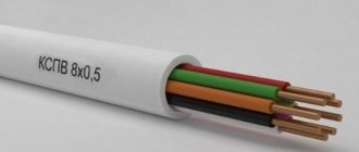
Wires
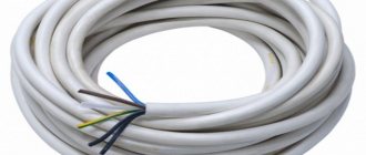
The main difference between a wire and a cable is the way it is laid; it cannot be used underground or underwater. They also have one or more aluminum or copper cores and PVC insulation. Wires with copper conductors are characterized by increased electrical conductivity, higher ductility and are more often used in household power supply than in industrial power supply.
Stranded copper wires in PVC
Marked with an alphanumeric code with the following designations:
- P - wire;
- B - PVC insulation;
- G - flexible.
The numbers indicate the number of cores and their cross-section.
Wires of grades PV1, PV2, PV3, PV4 are copper with polyvinyl chloride insulation, where the numbers indicate the flexibility class.
- PPV - two or three-core, flat with PVC insulation (used in lighting systems laid on walls);
- PVA - copper with twisted conductors in PVC insulation (used in everyday life as an extension cord, as well as for connecting household appliances, for example, vacuum cleaners);
- PBPP, PUNP - copper with PVC insulation, containing two or three cores (used in low current devices).
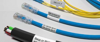
Cables for information transmission
The main characteristics of cables for information transmission include their flexibility, moisture resistance and low resistance of the conductor itself, which ensures data transmission with minimal delays. This applies to television, communication channels, etc. Therefore, cables with copper conductors in PVC insulation are most often used for these purposes.
For your information! RK-75, produced in accordance with GOST 11326, is often used as antenna cables that must provide high-speed signal transmission for radio and television. RK-75 has one or more copper cores and PVC insulation, which allows it to be used outdoors.
RK-75 are suitable for connecting antennas
Among the multi-core RK-75, the following modifications are distinguished:
- RK 75-2-13M. It consists of a stranded inner conductor insulated with solid polyethylene from the outer conductor, which is a braided copper wire. This radio frequency cable is used in television for transmitting satellite and cable television signals, as well as as a connection for video surveillance systems. The PVC shell allows it to be used both indoors and outdoors;
- RK 75-3-34M is a cable used in radio frequency communications, consisting of a multi-wire inner conductor and a braid of copper wires, separated by insulation made of porous polyethylene foam with white PVC insulation.
You might be interested in: Features of heat shrink tube
Important! The service life of such cables is 12 years.
The cables used to transmit digital information with minimal electromechanical interference are so-called twisted pair cables. Used primarily in computer networks and represents a physical medium for data transmission.
A twisted pair is a system of insulated conductors twisted together and combined into a single shell. Depending on the operating conditions, twisted pairs are produced in various modifications. They come in both shielded and unshielded, with the number of pairs from one to one hundred and in various shells.
Twisted pair cable is suitable for connecting a modem
The following concepts are used in labeling:
- F/FTP, S/FTP, S/STP - cables shielded with foil and/or braid;
- U/UTP - unshielded.
Types of shells are designated as follows: PVC shell - PVC, PVC shell fire-resistant, UV-resistant - FR-PVC.
Polyethylene (PE), polypropylene (PP), high-density polyethylene (HDPE) and low-density polyethylene (LDPE) coatings can also be used.
Special twisted pairs include the following:
- FR-LSZH - do not emit smoke and do not support combustion;
- Plenum - self-extinguishing cables that do not ignite again. Used in air ducts.
LED and electroluminescent
For decorative purposes, flexible LED and electroluminescent wires are used.
An LED cable is a flexible wire with a copper core that conducts current. Along it there are additional wires with multi-colored LEDs connected in series at a distance of 2 cm.
LED wires are more for decoration
Electroluminescent wires are thin cords made of polyvinyl chloride, inside of which there are copper conductors coated with a special substance - electroluminescent phosphor. The glow appears due to the effect of electroluminescence when exposed to alternating electric current. The central wire of such a cable is wrapped around a second contact - two wires, while the electroluminophor is covered with a thin layer of dielectric.
Note! The entire structure is enclosed in a PVC shell, which can be either transparent or colored.
Special types
Special-purpose cables and wires are designed specifically for operating conditions that differ from the average. These include both high humidity and abnormal weather conditions, as well as the aggressive environment in which the products are located.
Special cables are needed for aggressive environments
Marine cables intended for operation in conditions of high humidity can be produced either in PVC insulation or in a rubber sheath. Depending on the technical conditions, they are produced with increased fireproof properties, in which combustion does not spread in the bundles.
For rolling stock they are produced mainly in a cold-resistant PVC shell and are used in the operation of trolleybuses and rail transport.
You may be interested in: Cable and wire difference
When carrying out geophysical work, cables are used that can withstand the temperature range from −40 °C to 50 °C.
Compound
The quality of the connection of copper wires directly affects the electrical contact. There are several connection methods:
Twisting. The easiest option involves removing the insulation and twisting the bare wires. After which the product is re-insulated using PVC tape or special caps. Dissimilar alloys cannot be twisted.
Types of electrical cables and wires: device, purpose, marking and characteristics of the main types of cables used in houses and apartments (150 photos)Methods for laying cables in trenches: step-by-step instructions for laying and installing power cables in earthen trenches (140 photos)
- Types of cable channels and cable boxes: types, sizes and materials of manufacture. 120 photos and videos of cable channel installation
Soldering. The work takes longer than twisting. But the process guarantees a reliable connection. To solder copper wires, you need solder and rosin.
Terminal blocks. This is an insulating plate on which the contacts are located. Ideal for assembling dissimilar materials. Depending on the type of conductor fixation, they are available with a tightening screw or clamping plates.
Spring terminals. Fast and effective option. It is enough to tear off the insulation, exposing the core, and insert the terminal with a spring clip.
Photos of copper wires and cables
Did you like the article? Share
3+