What is a commutator motor and its features
The commutator is the part of the engine that comes into contact with the brushes. This unit ensures the transmission of electricity to the working part of the unit. A motor with at least one rotor winding connected to brushes and a commutator is called a commutator motor. Commutator electric motors are:
- direct current;
- alternating current;
- universal.
The commutator motor can be of direct or alternating current. There are universal models that can operate from any type of voltage source
The latter are universal, operating on both direct and alternating current. They remain popular, even though the presence of brushes is a negative point, since the brushes wear out and spark. This unit requires constant monitoring and maintenance. The advantages of commutator motors include the ability to smoothly adjust speed over a wide range and low cost.
Like other electric motors, a commutator motor consists of a stator and a rotor (often called an “armature”). Its distinctive feature is the presence of a collector unit on the shaft, through which power is transmitted to the machine. The design of DC and AC commutator motors are similar, but have certain differences, so let’s take a closer look at them separately.
Construction[edit]
Microelectric motors have an armature magnetic circuit made in the form of a three-pronged package made of stamped sheets of electrical steel.
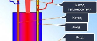
The figure shows: 1 - shield; 2 - anchor; 3 - body; 4 - collector; 5 - permanent magnets; 6 — bracket; 7 - gasket.
The armature loop winding, which has three shortened sections, is wound directly onto the teeth of the package and connected into a star or triangle. The origin is in the cover of the machine, and a three-lamella cylindrical commutator pressed into each section is attached to the commutator plate. The motor is powered through a brush assembly mounted on the armature shaft.
General structure of commutator motors
Like any electric motor, a commutator motor converts electrical energy into mechanical energy. It consists of a stationary part - the stator and a moving part - the rotor. The stator houses the field windings, the rotor is responsible for transmitting the resulting mechanical energy. One of the components of the rotor is the shaft. On the one hand, a collector unit is placed on the shaft, with the help of which electrical energy is transmitted to the rotor windings.
Commutator motor: device
The stator consists of a housing that protects the motor components from damage. Magnetic poles are attached to the top and bottom of the housing. They are necessary to maintain magnetic flux between the stator and rotor.
Electrical diagram
For practical work, it is convenient to use two types of its representation:
Simplified display
The method allows you to very simply imagine the connection of all motor windings to the electrical network diagram.
The switch breaks both phase and zero potentials or one of them. Through the brushes with the commutator, a current circuit is created along the rotor windings.
Schematic diagram
Depending on the design features of the stator and rotor windings, they may have additional taps for powering various control and automation devices of the commutator motor or do without them.
Thermal protection prevents overheating of the motor winding insulation. It removes the supply voltage when the sensor is triggered, stopping the rotation of the rotor and actuator.
The tachogenerator allows you to judge the speed of rotation of the rotor. For some engines it is replaced with a Hall sensor. To transmit signals to these devices, collector plate contacts are also used.
Commutator motor rotor
The rotor of a commutator motor consists of a shaft onto which an assembled magnetic circuit is mounted. On the one hand, the collector unit is attached to the shaft, on the other, the fan blades. To ensure easy rotation and for fixation in the housing, bearings are placed on the shaft on both sides. For normal operation of an electric motor, the rotor must be perfectly balanced. Therefore, the production of this part is especially scrupulous.
Moving (rotating) part
Rotor winding
The rotor core is assembled from metal plates stamped from magnetic metal. The thickness of the plates is 0.35-0.5 mm, each of them is filled with a layer of dielectric varnish to get rid of stray currents. The plates have grooves along the outer edge into which turns of copper wire are then placed. These plates are placed on the shaft and secured to it, and a package of the required size is assembled. This system is a magnetic circuit.
This is what the rotor of a commutator motor looks like
Turns of copper winding wire are placed in the grooves of the magnetic circuit. The outputs of the windings are output to the collector unit, where they are switched.
How the collector unit works and how it works
The collector unit is worth considering in more detail. Otherwise, it is difficult to understand how the rotor rotates. The collector has a cylindrical shape and is made of copper plates (sometimes called lamellas), which are insulated from each other by mica or textolite spacers. There is no electrical contact with the axis of the shaft to which it is attached.
The collector has the form of a cylinder, which is made of copper plates. The plates are made in the form of sectors, separated by dielectric spacers
It turns out that the collector is assembled from copper sectors and, without winding, are not electrically connected to each other. The output of one rotor winding frame is attached to each collector plate. Two brushes are pressed against the plane of two opposite commutator frames. They fit tightly to the surface of the copper collector plate, which gives good contact. Potential is applied to these brushes, which is transmitted to that turn of the rotor winding that is connected to these plates.
Graphite brushes are pressed against the paired commutator plates
Since the rotor rotates at a certain speed, one pair of plates is replaced by another. Thus, voltage is transmitted to all rotor windings. At the same time, the fields arising one after another support the rotation of the rotor, “pushing” it in the desired direction.
Principle of operation
Now, after we have looked at the rotor structure, we can talk about how a commutator motor works. Actually, the principle of operation is no different from other motors; the rotor begins to rotate in a magnetic field due to the currents induced on it. But how exactly and why are these currents induced? To understand, we need to remember how electromotive force arises in a constant magnetic field. If a rectangular frame is inserted into the field of a permanent magnet, it begins to rotate under the influence of the current arising in it. The direction of rotation is determined by the gimlet rule. For a constant field, it says this: if you insert your right hand into the field so that the magnetic lines enter the palm, the outstretched fingers will indicate the direction of movement.
Illustration to explain the operating principle of a brushed DC motor
If you look at the structure of the rotor, we see that each winding represents such a frame. Only it consists not of one wire, but of several, but this does not change the essence. With the help of a collector unit, at some point in time, the winding is connected to the power supply, current flows through it and a magnetic field arises around the conductor. It interacts with the stator field. Depending on the type, there are permanent magnets there or a direct current also flows in the windings, generating its own magnetic field at the poles. The fields of the rotor and stator are designed so that when they interact, they “push” the rotor in the desired direction. Here, briefly and without much detail, is a description of the operation of a brushed DC motor.
The windings on the rotor are connected to the commutator plates. When the brushes come into contact with the plates, we get a closed circuit through which current flows
If you think about it a little, you can understand why a brushed motor allows you to easily and smoothly regulate speed. The more voltage is applied to the rotor windings, the more powerful the field the stator generates, the stronger their interaction and the faster the rotor spins, as it is pushed with greater force. If the voltage is reduced, the interaction is less, and so is the resulting rotation speed. So all you need to do is regulate the voltage, and this can even be a simple potentiometer (variable resistance).
Asynchronous or collector?
There is no clear answer. Why is that? The difference lies in the specifics of operation. For industrial operation, it requires increased technical characteristics, which have asynchronous type installations.
Household use does not require special functional properties, and therefore units equipped with a collector unit are in this case more popular than brushless ones. UCD or asynchronous ones effectively perform assigned tasks within the framework of the technical processes intended for them.
Advantages and disadvantages
As usual, let's start by listing the advantages. The advantages of commutator electric motors are:
- Simple device.
- High speed up to 10,000 rpm.
- Good torque even at low speeds.
- Low cost.
- Ability to adjust speed over a wide range.
- Low starting currents and loads.
Commutator motor diagram
Not bad qualities, but there are also disadvantages, and they are no less serious. The disadvantages of commutator electric motors are:
- High noise level during operation. Especially at high speeds. The brushes rub against the commutator, creating additional noise.
- Sparking of brushes, their wear.
- The need for frequent maintenance of the collector unit.
- Instability of indicators when the load changes.
- High failure rate due to the presence of a commutator and brushes, short service life of this unit.
In general, a commutator motor is a good choice, otherwise it would not be installed on household appliances. To be fair, it should be said that with normal performance quality, such engines operate for years. They can work for 10-15 years without problems.
FAQ[edit]
How to break in a commutator motor[edit]
A commutator motor requires “breaking in” just like model internal combustion engines, only instead of a liner and a piston, graphite brushes are required for lapping in a commutator motor.
The brushes of the new motor have a small contact area with the commutator, because of this, the current passing through the brushes heats them up greatly, which can cause damage, chipping or “sticking” of the brushes to the commutator. In order to avoid this, it is necessary to “break in” the collector as follows (in relation to a car model):
- “Hang” or turn the model over so that the wheels do not touch the surface;
- Turn on the model and start the engine at low speed. To do this: in any convenient way, fix the “trigger” of the control panel at 15-20% of the move to the left or right relative to the “neutral”;
- Let the collector work for 30-40 seconds;
- After stopping, blow out the engine to remove any waste brush material;
- Start the engine for another 2-3 minutes, according to point 2;
- Bleed the engine again.
Brushed DC motor with magnets
In brushed DC motors, a constant magnetic field is provided by:
- permanent magnets;
- field windings.
Magnets and windings are located on the stator housing, and most often at the top and bottom. If we talk about low-power motors, then commutator motors with permanent magnets are more popular. They are easier to manufacture, cheaper, and quickly respond to changes in voltage, which allows you to smoothly regulate the speed. The disadvantage of motors with permanent magnets is their low power, and also the fact that over time or when overheated, the magnets lose their properties and this leads to deterioration in the performance of the motor.
Commutator DC motor design
Such motors have low power, from a few to hundreds of watts. They are used in technology for which smooth speed control is important. These are usually children's toys, some types of household appliances (mainly fans). The disadvantage of a commutator motor with magnets is the gradual loss of power; the magnets become weaker over time, and the already small power drops. But recently, new magnetic alloys with high magnetic force have appeared, making it possible to create engines with high power.
Thermal effect of starting current
If we move on to the formulas, the starting current has a thermal effect on the electric motor, which is described by the so-called Joule integral. Simply put, the thermal energy produced by an electric current is proportional to the square of the current multiplied by the time. This quantity is denoted by I2t.
The good news is that the circuit breaker has approximately the same thermal (time-current) characteristic as the time-current characteristic of motor acceleration.
Compare:
Time-current characteristics of the circuit breaker
What do we see? To protect the engine, automatic machines with characteristic D are mainly used, precisely in order to react less to short-term overloads. Read more here.
And for the motor starting current the graph will be something like this:
Starting current graph (theoretical) at Kp = 6
The linearity of the graph is conditional. It all depends on the change in load torque during acceleration. The theoretical graph is shown with a dotted line. On this graph Kp = Ip / In = 6, but this is a theoretical (tabular) value. Acceleration time to nominal = tп.
The actual graph is drawn with a solid line. On it Iп` is the real value of the starting current, which is always less than the theoretical one. This is due to the fact that the supply network has non-zero resistance, and as the current increases, voltage losses occur on the wires.
I wrote about losses at low voltage here, and about losses in 0.4 kV networks here.
It is clear that due to losses, the acceleration time will be longer; it is indicated on the graph by tп`.
Now let's rotate the last graph to bring the axes to the same coordinate system:
Time from current, so to speak
Isn’t it very similar to the time-current characteristic of a protective motor?
It turns out that both characteristics compensate each other, and when choosing a machine, it is enough to adjust its setting to the rated current of the motor. For particularly difficult starts, when the area under the motor starting curve is greater than the area under the curve of the circuit breaker, it is worth thinking about a soft start - soft starter or inverter.
With field windings
DC motors with excitation windings have found wider application. This type of engine powers cordless power tools: angle grinders, drills, screwdrivers, etc. The field windings are made of insulated copper wire (in a varnish sheath). The grooves in the pole pieces are used as a basis. Windings are wound on them as a base.
Commutator motor with winding excitation system
If we look at the design of a commutator motor, we see two unrelated devices, the rotor and the field windings. The characteristics and properties of the engine depend on the method of their connection. There are four ways to connect the rotor and field windings. These methods are called excitation methods. Here they are:
- Independent. This is only possible if the voltages on the field winding and the armature are unequal (this happens very rarely). If they are equal, a parallel excitation circuit is used.
- Parallel. Speed is well regulated, stable operation at low speeds, constant characteristics, independent of time. The disadvantages of this type of connection include instability of the motor when the inductor current drops below zero.
- Consistent. With this connection, you cannot turn on the motor with a shaft load below 25% of the nominal one. When there is no load, the rotation speed increases greatly, which can destroy the engine. Therefore, this type of connection is not used with a belt drive; if the belt breaks, the motor is destroyed. The series drive circuit has high torque at low speeds, but does not work very well at high speeds, making it difficult to control the speed.
- Mixed. Considered one of the best. Handles well, has plenty of low-end torque, and rarely gets out of control. Among the disadvantages is the highest price compared to other types.
Methods for connecting field windings
Brushed DC motors can have an efficiency from 8-10% to 85-88%. Depends on the connection type. But high-performance ones are characterized by high speeds (thousands of revolutions per minute, less often hundreds) and low torque, so they are ideal for fans. For any other equipment, low-speed models with low efficiency are used, or a gearbox is added to productive models; no other solution has yet been found.
Operating time and starting current value
The duration of the starting current will be considered the time during which the current decreases from the maximum (Iп) to the nominal value (Iн). This duration is actually equal to the acceleration time from zero to the rated rotation speed.
The whole question is what is the duration of this current - 10 milliseconds (half a period) when the engine is idling, or 10 seconds when there is a massive impeller on the shaft. Theoretically, it is impossible to calculate this time. However, I will share some thoughts.
As I said above, the motor current at start-up can exceed the norm several times (Kp). And some novice electricians who do not read my blog believe that the circuit breaker should be chosen in the same way - for a higher current. In articles and even instructions they write that “When choosing a machine, it is necessary to take into account that the starting current of an asynchronous electric motor is 5 - 7 times higher than the rated one.” How to take this into account? Is it really possible to choose the current of the machine 5-7 times higher than the rated current of the motor?
Example:
Nameplate of a Chinese electric motor 30 kW
Written – 56 A. What does this mean? Is it really true that the current of the circuit breaker should be more than 300 A? Of course not. And the choice of machine in this case depends not only on the rated current of the motor (56 A), but also on the duration of the starting current.
By the way, let's investigate and find out the starting current of this motor. After all, we are not destined to get to the website of this Chinese manufacturer. Initial nominal data: power - 30 kW, torque - 190.9 N m, current - 56 A. We look at the catalogs of domestic manufacturers, looking for a similar engine, because the laws of physics are the same in both Russia and China. We find (catalog at the end of the article): this is a 1500 rpm motor, 4 poles, with a starting current multiplicity Kp = 7. As a result, we get: Iп = In · Kp = 56 · 7 = 392 A. This is a theoretical starting current, but it is not machine setting current!
The starting current is the maximum possible current . The maximum current will be at start-up, that is, when the engine is stopped. That is, the starting current is ALWAYS present, and its initial value is always prohibitive. In the case of our Chinese engine - 392 A, if we take the short-circuit current of the supply network equal to infinity (voltage source with zero internal resistance).
Universal brushed motors
Despite the fact that the collector unit can be called the weakest point of the electric motor, such models are widely used. All thanks to the low price and ease of speed control. AC commutator motors are found in almost any household appliance, both large and small. Mixers, blenders, coffee grinders, hair dryers, even washing machines (drum drive).
Universal commutator motor operates on direct and alternating voltage
In structure, universal commutator motors do not differ from DC models with field windings. There is certainly a difference, but it is not in the device, but in the details:
- The excitation circuit is always sequential.
- The magnetic systems of the rotor and stator to compensate for magnetic losses are made of the laminated type (a single system without continuous cuts).
- The field winding consists of several sections. This is necessary so that the operating modes on direct and alternating voltage are similar.
The operation of universal-type commutator electric motors is based on the fact that if you simultaneously (or almost simultaneously) change the polarity of the power supply on the stator and rotor windings, the direction of the resulting torque will remain the same. With a series drive circuit, the polarity changes with very little delay. So the direction of rotation of the rotor remains the same.
Advantages and disadvantages
Although universal commutator motors are actively used, they have serious disadvantages:
- Lower efficiency when operating on alternating current (when compared with operating on direct current of the same voltage).
- Strong sparking of the collector unit on alternating current.
- They create radio interference.
- Increased noise level during operation.
In many models of construction equipment
But all these disadvantages are offset by the fact that at a supply voltage frequency of 50 Hz they can rotate at a speed of 9000-10000 rpm. Compared to synchronous and asynchronous motors, this is a lot; their maximum speed is 3000 rpm. This is what led to the use of this type of motor in household appliances. But they are gradually being replaced by modern brushless motors. With the development of semiconductors, their production and management are becoming cheaper and easier.
Areas of use
Due to the fact that the universal motor can have a high rotation speed when operating from a single-phase AC network without the use of additional converting devices, it is widely used in household appliances such as vacuum cleaners, blenders, hair dryers, etc. The universal electric motor is also widely used in such tools like drills and screwdrivers.
Due to the fact that the rotation speed of the universal motor is easily regulated by changing the supply voltage, it was previously widely used in washing machines. Nowadays, thanks to the development of converter technology, brushless electric motors (PMSM, ADKR), the rotation speed of which is regulated by changing the frequency of the supply voltage, are becoming more widely used.
see also
Basic parameters of the electric motor
General parameters for all electric motors
- Motor torque
- Motor power
- Efficiency
- Rated speed
- Rotor moment of inertia
- Rated voltage
- Electrical time constant