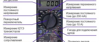
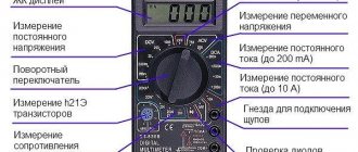
Multimeter appearance and connectors
On the front of the tester, all the inscriptions are made in English, and even using abbreviations.
What do these inscriptions mean:
- OFF - the device is turned off (to prevent the device batteries from running out, set the switch to this position after measurements)
- ACV - measurement of variable U
- DCV - constant U measurement
- DCA - DC current measurement
- Ω - resistance measurement
- hFE - measurement of transistor characteristics
- diode icon - continuity test or diode test
Switching modes occurs using the central rotary switch. When you first start using your digital multimeter, it is recommended that you immediately mark the pointer mark on the switch with contrasting paint. For example like this:
Power is supplied from a Krona battery. By the way, by looking at the connector for connecting the crown, you can indirectly judge whether the tester was assembled in a factory or somewhere in Chinese “cooperatives”. With high-quality assembly, connection occurs through special connectors designed for the crown. Lesser quality options use regular springs.
The multimeter has several connectors for connecting probes and only two probes
Therefore, it is important to correctly connect the probes to measure certain quantities, otherwise you can easily burn the device
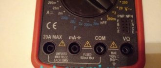
The probes are usually of different colors - red and black. The black probe is connected to the connector labeled COM (translated as “common”). Red probe into the other two connectors. The 10ADC connector is used when it is necessary to measure current from 200mA to 10A. The VΩmA connector is used for all other measurements - voltage, current up to 200mA, resistance, continuity.
The main criticism is caused by the factory probes that come with the device. Almost every second owner of a multimeter recommends replacing them with better ones. However, their cost can be comparable to the cost of the tester itself. As a last resort, they can be improved by strengthening the bends of the wires and insulating the tips of the probes.
If you want high-quality silicone probes with a bunch of tips, then you can order them with free shipping on AliExpress here.
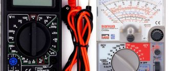
Previously, pointer testers were also widely used. Some electricians even prefer them, considering them more reliable. However, due to the large error of the measurement scale, it is less convenient for ordinary consumers to use them. In addition, when working with a dial multimeter, it is imperative to guess the polarity of the contacts. For digital ones, if they are connected to the poles incorrectly, the readings will simply be displayed with a minus sign. This is normal operation and will not damage the multimeter.
Basic Multimeter Operations
Voltage measurement
How to use a digital multimeter to measure voltage? To do this, set the switch on the multimeter to the appropriate position. If this is the voltage in the outlet at home (alternating voltage), then flip the switch to the ACV position. Insert the probes into the COM and VΩmA connectors.
First of all, check that the connectors are connected correctly. If one of them is mistakenly installed in contact 10ADC, a short circuit will occur when measuring voltage.
Start measuring from the maximum value on the device - 750V. The polarity of the probes does not play any role at all. It is not necessary to touch the zero with a black probe, and the phase with a red one. If a much lower value is displayed on the screen, and the number “0” appears in front of it, this means that for a more accurate measurement, you can switch to another mode, with a smaller voltage level scale that your multimeter allows you to measure.
When measuring DC voltage (for example, electrical wiring in a car), switch to DCV mode.
And you also start measuring from the largest scale, gradually lowering the measurement levels. To measure voltage, you need to connect the probes in parallel to the circuit being measured, while using your fingers to hold only the insulated part of the probe so as not to get under voltage yourself. If the display shows a voltage value with a minus sign, this means that you have reversed the polarity.
ATTENTION: when measuring voltage, be sure to check that the multimeter scale is set correctly. If you start measuring voltage with the DCA switch in the on position, i.e., measuring current, you can easily create a short circuit right in your own hands!
Some experienced electricians recommend holding both probes in one hand when measuring the voltage in an outlet. If the probes are poorly insulated and breakdown, this will allow you to protect yourself to some extent from electric shock.
The multimeter operates on a battery (a 9-volt crown is used). If the battery starts to run low, the multimeter starts to lie shamelessly. In the outlet, instead of 220V, it may seem like 300 or 100 Volts. Therefore, if the device readings begin to surprise you, first check the power supply. An indirect sign of battery discharge can be chaotic changes in the readings on the display, even when the probes are not connected to the object being measured.
Current measurement
The device can only measure direct current. The switch must be in the – DCA position.
Be careful! When measuring current, if you do not know approximately what limits the current will be, it is better to start measuring by inserting the probe into the 10ADC connector, otherwise measuring a current of more than 200mA at the VΩmA connector can easily blow the internal fuse.
Here, probes, unlike voltage measurements, must be connected in series with the object being measured. That is, you will have to break the circuit and then connect the probes into the resulting gap. This can be done in any convenient place (at the beginning, middle, end of the chain).
Current measurement
Using a multimeter to measure direct or alternating current, you need to insert the red probe into the mA socket, the black one into the com. If the current measurement is carried out with a variable source, then the switch is moved to the department - A~, with a constant one: A–.
The main condition for how to correctly measure current with a multimeter is to install the device in the circuit in series. Experts have a negative attitude towards using a multimeter as a tester to check large current consumption (for example, above 10 amperes). It is better to do this with electrical clamps. Therefore, it is better not to measure current with a multimeter.
The whole point is not in the tester itself, because it itself is protected by a metal bracket, through which large currents are checked. The bracket is installed internally and has a diameter of 1.5 mm. This size is capable of withstanding a significant amount of measured current in 10-12 seconds. It's all about the probe wires. They are thin and, of course, not designed for heavy loads.
Use in DC current measurement
It should be noted right away that the 830 series devices can only measure DC values, which is why they cannot be used to measure values in an AC circuit. For these purposes, you need to find another device. To measure current, a multimeter must be connected to the open circuit of the circuit that is being measured.
You also need to determine the maximum possible current value in the circuit. If it is less than 200 mA, then the appropriate limit must be selected. Then the red probe is connected to the VΩmA socket, and the multimeter is turned on. It is advisable to connect it to the circuit when the voltage there is removed. Another important nuance is that the characteristics of devices from some manufacturers do not advise turning on the device more than fifteen seconds before starting to measure current at a limit of ten amperes.
Application of General Purpose Multimeter
A general purpose multimeter is a measuring instrument designed to measure currents, voltages and resistances in household networks, devices and cars.
A typical representative of such a multimeter is the MAS 830L device.
It is made according to the classical scheme. The device includes:
- LCD indicator14 for visualization of measurement results;
- digital scale backlight switch 2;
- self-diagnosis mode switch 1;
- mode switch;
- probe sockets 7, 8, 9;
- connector for connecting transistors 10.
The impact-resistant multimeter body is housed in a rubber casing to increase mechanical resistance.
Preparing the device for operation
Before starting work, insert the probes into the sockets. One probe is inserted into the common connector – it is marked “com”, and the second – depending on what you will measure: for voltages and resistances, choose the connector marked U and R, and for current – marked A.
Next, turn on the device: to do this, simply move the switch to the desired position: for voltages this is section U, current – A, and resistances – R. The screen should show zeros for the voltage and current measurement mode, and one for the resistance measurement mode. If you see a battery icon, replace the multimeter's power supply.
To check the integrity of the probes, some technicians first turn on the device in resistance measurement mode and short-circuit the probes; the screen should show zero resistance; if this is not the case, then they check the probes and their wires.
How does a multimeter work?
- The dial shows the measured values as numbers on a plastic or glass display.
- The switch allows you to change the functions of the device, as well as switch ranges. When not in use, it is set to the “Off” position.
- Sockets (connectors) in the housing for installing probes. The main thing, with the inscription COM and negative polarity, has a general purpose. A probe with a black wire is inserted into it. The next one, marked VΩmA, has positive polarity with a red probe.
- Test flexible wires red and black with clamps.
- Panel for monitoring transistors.
Types of multimeters
According to the type of indication of measured values, multimeters are classified into:
- switches;
- digital.
In dial multimeters, a magnetoelectric microammeter with a system of switching shunts and diode assemblies is used as a basic measuring device. The analog scale has divisions for measuring electrical quantities. Type of dial multimeter.
In digital multimeters, the analog measured signal is converted into a digital one, then the information is processed and transmitted to a digital scale. Digital multimeters have a number of advantages over dial ones:
- increased measurement accuracy;
- clarity of indication;
- mechanical resistance to falls;
- ease of use by non-professionals.
Manufacturers produce multimeters for general and special purposes.
Special digital multimeters can be designed for:
- measurements of large electrical quantities;
- control of climatic parameters (pressure, temperature);
- measurement of parameters of radio components (resistance, capacitance, inductance).
How to find out voltage and current. Sequencing
To determine voltage using a multimeter, proceed as follows:
- Select the desired mode on the device.
- Set the range of values. For a 220 V outlet this is 600 or 750 V. If you don’t know the exact data, set the maximum.
- Connect the probes to the multimeter: black - to the COM connector, red - to VmA.
- Attach the second ends of the rods to the object being measured. If you see a negative indicator on the screen, it means you have mixed up the probes.
When measuring current, you need to be especially careful. If performed incorrectly, the procedure is unsafe for humans and the device. The main feature is that the probes need to be connected not in parallel, but in series. The readings should be taken as soon as possible. The rest of the algorithm is approximately the same:
- current determination (AC or DC);
- selecting the appropriate mode on the device;
- setting a range of values (exact or maximum);
- serial connection of probes;
- reading readings from the display.
You need to use the multimeter very carefully, because you are dealing with electricity
It is important to take into account all the nuances and remember that the basis for successful work is compliance with safety rules. All other skills will come with experience.
Voltage measurements
The device has high-voltage voltage measurement ranges, but they are not useful for repairing car electrical equipment. And high-voltage wires are checked only for the absence of internal breaks with an ohmmeter. The remaining high-voltage elements of the car's electrical equipment are also not checked with a voltmeter. Of these, using DT 832 you can only check the resistor in the ignition distributor slider, but it should also be checked in ohmmeter mode.
To measure voltage, connect the probes to the lower and middle sockets on the front side of the device. Using the switch located there, select the mode for measuring direct voltage up to 20 V (V ─ 20). Ensure that the probe of the common wire DT 832 is in contact with the ground of the car, and the other probe is in contact with the section of the wiring where measurements need to be taken. Read readings from the display.
High-voltage ranges for measuring alternating voltage will be useful to you in order to test the wiring in the apartment.
Device information
The DT830B model is a multifunctional measuring instrument - a multimeter, which is widely used among electricians. Using this universal tool, you can determine the required parameters and electrical characteristics in the shortest possible time.
The main difference between the DT830B digital device and analog instruments is the ability to measure many parameters, and all obtained data is presented in digital format. All elements of the circuit are placed in a small case, on the front of which the main switch is installed in the center. It is the main control element and covers approximately 20 positions.
There are icons around the circle indicating the corresponding operating modes. All obtained measurement data is displayed on a digital liquid crystal display.
Types of devices and their features
As the name suggests, the tool has extensive functionality. It helps to measure several parameters at once - voltage, current, resistance, etc. Using a multimeter, you can check the integrity of the electrical circuit and detect defects that require repair. Electricians have a professional term for this procedure - “diagnosis”, since the operation of the device is accompanied by a sound or light signal.
Before you start using the multimeter, carefully study its design. There are 2 main types of devices: analog (aka pointer) and digital. Multimeters of the first category are well known to electricians with considerable experience. In Soviet times, pointer devices were called avometers and “tseshki”. Such testers provide stable readings and do not respond to interference. Bonus: low price.
With the advent of digital technology, analog multimeters have become obsolete. This is facilitated by a considerable number of disadvantages of pointer instruments:
- low sensitivity of the avometer;
- tendency to mechanical stress;
- significant error in determining the data;
- difficulties in work for beginners;
- the need to strictly maintain polarity.
In comparison with a dial multimeter, its improved digital “ancestor” has one significant drawback - sensitivity to interference (radio, electromagnetic). But it has more advantages:
- high performance in any position;
- small error - from 0.1 to 1%;
- convenient display of data;
- lack of connection between polarity and voltage indicators.
Technical features
Voltage tester
Common parameters:
- indication – liquid crystal display (3.5 digits);
- automated determination of units of measurement, polarity;
- overload indicator with built-in protection for each limit;
- number of switch positions – 20;
- frequency of measuring actions – from 2 to 4 per second;
- measuring range el. resistance – from 0.1 Ohm to 2,000 kOhm;
- rated current for testing transistors – 100 µA;
- Height x Width x Depth in mm – 126 x 70 x 28;
- Weight (without battery) – 137 g.
How to use a multimeter correctly: general definitions
These devices are designed to measure current, voltage, resistance and other electrical parameters. There is no point in disassembling the device, since modern equipment of this class is highly complex. Its repair is impossible without professional skills and specialized metrological equipment.
Previously, only pointer instruments were used
But using digital devices is easier. It's easier to read the readings from the screen. Do not have a strong influence on the vibration measurement process. The absence of mechanical moving parts increases durability.
When choosing a model, pay attention to the following parameters:
- Measurement limits and discreteness.
- The display is of sufficient size and backlit.
- Shape, size, weight.
- Equipment that increases the level of comfort.
- Additional functionality.
Retractable stand allows you to install the device in a convenient position
If properly equipped, the multimeter can be used to measure room temperature
Good ergonomics ensure a secure hand grip. Damping pads increase resistance to mechanical stress
This device performs the functions of a multimeter and oscilloscope.
Multimeter M832 - instructions
As often happens, the instructions for the M832 are universal and are designed for a number of devices with different technical parameters. For example, this model does not provide the ability to measure temperature, although the instructions describe this option. This can be confusing for an inexperienced user.
The battery that was in the package along with the device is of quite high quality and you will be surprised to learn that the new battery costs separately almost as much as the entire device in the kit.
A typical drawback of this device and similar inexpensive multimeters is the unreliable fastening of the measuring probes to the wires. In fact, the probes are held on several thin copper conductors, and after the conductors break, due to the design of the probe, it is impossible to solder them back.
To avoid this, immediately before starting operation, securely fix the wire at the base of the probe using electrical tape or cold welding.
We recommend that you immediately buy high-quality ones and use them in all your (this and future) testers. The review was prepared specifically for the Tekhnoobzor website by Denev. Please read these instructions before using the device. Failure to understand or use this manual correctly could result in serious injury.
Main characteristics
Devices type M-83 are a series of compact, pocket-sized (3 ½) electrical multimeters designed for measuring DC and AC voltage, DC current, resistance and diodes. Some of them are also used to measure temperature, hFE and sound duration, or simply as an oscillator. These M-83 devices are equipped with full voltage protection; these are ideal tools for use in laboratories, workshops/shops or home use.
Front Panel Description
- Function and scope of the switch. The switch is used to select the desired function and scope, as well as to turn on the device. To ensure the battery lasts as long as possible, keep the switch in the “OFF” position when the device is not in use.
- Display 3 ½ digits, 7 segments, 0.5 height LCD
- “Regular” (COM) compartment Insert the black (negative) end of the wire into the connector (#3 “COM”)
- V m ACx compartment This is the connector (#4) for the red (positive) end of the wire for all voltage, resistance and current (except 10A), i.e. to measure them.
- “10A” compartment Connector with red wire end for measuring 10A.
OPERATING INSTRUCTIONS
Warning.
- To avoid electric shock or damage to the instrument, do not attempt to measure voltages that may exceed 500 volts.
- Before using the tool, check all parts of the device (e.g. wires, connectors, etc.) individually.
DC voltage measurement.
- Connect the red end of the wire to the “V Ω mA” compartment, the black end to the “COM” compartment.
- Set the switch to the desired DCV position; if the measured voltage is unknown in advance, set the switch to the highest limit and lower it to satisfactory readings from the device.
- Connect the wires to the mechanism, device or circuit being measured.
- Turn on the device and the voltage value will appear on the electronic display along with the voltage polarity.
AC voltage measurement.
- Red wire “V Ω mA”, black with “COM” (for measurements between 220 mA and 10 A, connect the red wire to the 10 A compartment).
- Set the switch to the selected DCA position.
- Open the circuit to be measured and connect the wires in series with the load inside.
- Read the current reading on the display.
Transistor hFE measurement.
- Set the switch to hFE position.
- Determine whether the transistor is PNP or NPN type and whether it accommodates the emitter, base, and connecting wires. Insert the wires into the correct holes in the hFE socket on the front panel.
- The meter will show the approximate value of hFE, provided that the main current is 10 mA and V ce 2.8V.
Temperature measurement.
- Connect the K-type thermoelectric element to the “V Ω mA” and “COM” compartments.
- Set the switch to the “TEMP” position
Measuring room temperature.
M-835 can be used to measure room temperature (from 0°C to 35°C) without a thermoelectric element. Simply set the switch to the RT position and the current room temperature will appear on the display.
Capacitance measurement.
- Set the function switch to the position you want to use.
- Connect the capacitor under test to the “V Ω mACx” compartment and “COM”.
Sound check.
- Connect the red end of the wire to “V Ω mA”, the black end to “COM”
- Set the switch to the “sound” position.
- Connect the wires to two points on the circuit being measured. If the resistance is below 100Ω, a beep will sound.
Frequency measurement.
- Set the switch to “|_|¬”
- The tested signal (50 Hz for M-835...) will appear between the “V Ω mA” and “COM” separators, the voltage power is approximately 5V solution with 50KΩ impedance.
Replacing the battery and fuse.
The fuse rarely needs to be replaced, and almost always blows due to a mechanic's error. If the battery symbol appears on the display, you need to replace it. In order to replace the battery or fuse (200 mA/250V), you need to unscrew two screws at the base of the tool, then simply replace the old battery with a new one. Be careful not to reverse the polarity.
Carefully. Before attempting to open the base of the tool, disconnect the wires from the circuits to prevent electric shock.
Even at school, each of us was introduced to many interesting measuring instruments in a physics course: ammeter, voltmeter, ohmmeter and others - each of them was intended for only one type of measurement. However, today we have the opportunity to use a multimeter, which combines several measuring instruments at once.
There are two types of multimeters: digital and analog (arrow). In our article with video, we will look at both types of devices and learn how to use each of them correctly.
Operating modes
The desired operating mode is set by the switch by placing its handle opposite the corresponding sector:
DCV. Additionally divided into five ranges. This sector is intended for measuring DC voltage in the range 0-500V. Maximum voltage occurs infrequently, for example during TV repair
When the switch is set to 500V, an HV warning icon will appear in the upper left corner of the display to indicate the maximum level and the need for attention and caution. If the voltage value is unknown in advance, switching is performed from the maximum position with a gradual transition to lower values
Failure to comply with this condition may lead to inaccurate readings or failure of the device. ACV. Designed for measuring alternating voltage. The sector is divided into two parts - 200 and 500V. When using the 220-380V range you need to be extremely careful. The procedure is the same as in the previous constant voltage sector. DCA. This sector performs the function of a milliammeter and is intended for measuring small direct currents. It is not recommended to use this sector unless necessary, and caution should be used when measuring large currents. In this case, you need to ring the chain for no longer than a few seconds. hFE. The sector performs continuity measurements of transistors and checks for breakdown or breakage. Elements are tested regardless of their conductivity. The legs of the transistors must be placed in the appropriate sockets, as indicated on the special socket. DIODE sector. When the diode is working properly, the voltage drop in the forward direction is shown in the range of 400-700 mV. For the reverse direction, infinity is used. If the diode is faulty, then a value close to zero means a breakdown, and one close to infinity means a break. OM sector. Used for resistance measurements. The measurement range is in the range of 200-2000000 Ohms. You should take into account the errors of the Chinese multimeter and its too high sensitivity when making accurate measurements. It is imperative to take into account the resistance that occurs when the probes are connected to each other. This is especially true when measuring resistances that are too small.
Current measurement
The current consumed by any electrical device in the car. Disconnect the power supply circuit of the electrical appliance. Connect the probes to DT 832 to the lower and upper sockets. Set the mode switch to the current measurement position for a current slightly greater than the device can consume. If the consumer is not low-power, it will be mode A 10. Connect DT 832 to the power supply. Connect the common wire of the tester to the wire coming from the consumer. Connect the probe connected to the upper socket of the tester to the wire supplying power. When the consumer is turned off, the tester will show you the leakage current of the electrical appliance. When you turn it on, you will see the current it consumes on the display.
To measure voltage, the input of the measuring device is connected in parallel to the vehicle's on-board network. To measure current strength, the tester input should be connected only to the power supply or ground of the electrical device. Since connecting a multimeter in ammeter mode parallel to the vehicle's on-board network will lead to a short circuit with unpleasant consequences, including failure of the device. Also, do not try to measure the current drawn by the starter. Since it is tens of times greater than what is permissible for this device. The result will be failure of the device.
Why measure voltage and current?
The multimeter is designed to check the parameters of electrical networks and electronic components. To an inexperienced person, operating this device will seem difficult. But in fact, it is enough to understand the principle of taking readings and setting settings. After this, it will seem that without it you can’t even change the socket, and this is true.
Multimeter capabilities
What kind of device is this, and what functions can it perform? At the first stage of familiarizing yourself with the operation of a multimeter, you need to understand its settings and capabilities. On almost all models, the designations are written in Latin letters and are abbreviations or abbreviations from English terms.
Now, knowing the “language” of the device, you can begin to study its capabilities. The name multimeter (or multitester) means a wide range of measurements of various electrical quantities:
- Constant and alternating voltage and current.
- Resistance value.
- Capacity. This feature is found mainly only in professional devices.
For household needs, you can purchase a standard digital multimeter with an optimal set of functions. Since domestic manufacturers practically do not produce devices of this class, the choice is made on foreign digital multimeters.
The operating panel of the device is divided into two conventional sectors - the LCD display and the settings block. The latter most often represents a circular switch with markings applied around it. It, in turn, is divided according to the measured quantities with the maximum value of the measurement boundaries.
Measurements are performed using probes, which are installed in special sockets on the device.
Before testing begins, the batteries and functionality of the device are checked. By turning the switch to any position other than “Off,” the indicator should display zeros. Now you can begin measuring the quantities of interest.
First, the upper limit level is set. For example, for a constant voltage it can be from 200 mV to 1000 V. If at least the order of the value is known, the upper limit closest to it is set. Otherwise, it is recommended to set the maximum value and reduce it until numbers other than zero appear on the indicator during the measurement process. If you do not follow this technique, there is a possibility of device failure.
Voltage
Almost all household appliances and batteries operate on constant voltage. This is the most frequently measured quantity. The first experience of taking testimony will begin with it.
We install the probes in accordance with the color markings. If this is not observed, find the designation “+” or “-” on the probe body. After this, the maximum value of the constant voltage force is set. In our case, this is 1000 V. Next, the probe contacts touch the corresponding poles of the element under test. In this case, you don’t have to worry about incorrect polarity - the value on the screen will only change its sign.
Lowering the limit limit by switching the handle, we stop when stable readings appear on the display.
AC voltage is measured using the same principle. The exception is the lack of polarity.
Current
When measuring DC current, you should consider in advance how the multimeter will be connected to the circuit under test. This task is considered individually for each case. If you have no experience in drawing up such diagrams, it is best to study the theory first. Otherwise, there is a high probability of damage to the multimeter.
Another important point is the location of the probes in the sockets. If the desired current parameter is guaranteed to be less than 200 mA, then their location remains standard. But for readings above 200 mA and up to 10A, one of the probes is installed in a special connector.
Below are the simplest examples of measuring current of various sizes.
Resistance
Measuring resistance values can be useful not only for checking electrical network parameters. This function will be useful when installing electric underfloor heating or any other heating systems that run on electricity.
The measurement principle is completely similar to the steps of finding the value of constant voltage. It is necessary to move the toggle switch to the desired sector.
Professional electricians and electronics engineers, in addition to these basic types of readings, know many other parameters that can be found directly or indirectly using a multimeter. But for everyday needs, the information described above will be enough, and soon using a multimeter will be as familiar as
How to measure with a multimeter.
How to measure current with a multimeter.
This model allows you to measure a maximum of 10 Amps. To determine the current consumption, connect a multimeter in series to a household appliance, as shown in the picture.
Most often it is done as follows: the device is connected to the break of one phase wire going to the consumer being measured.
Attention, if a separate terminal is provided for measuring current above 200 mA, do not forget to move the probe to the appropriate place
How to measure voltage with a multimeter.
In a home electrical outlet, a multimeter can only measure alternating voltage with an upper limit of 700 Volts. Power supplies and batteries must be measured observing polarity in the DC voltage measurement mode, setting the upper limit with a margin.
How to test a battery with a multimeter.
I’ll say right away that in order to effectively check a car battery, you need a special load plug that measures the voltage under load, otherwise you will not be able to qualitatively determine the condition of the car battery.
For ordinary AA batteries, to check the condition, you need to set the switch to the maximum limit for measuring direct current and literally short it with a wire for no more than half a second in order to have time to see the readings on the screen. Do not hold for more than 0.5 seconds. - this causes breakdown or deterioration in the performance characteristics of the battery.
For 1-2 volt batteries in good condition, the short circuit current must be at least 2 Amperes. If it is less than 1 Ampere, then you will have to buy a new one or use it for control panels for household appliances in the house.
How to measure resistance with a multimeter.
I want to say right away that you cannot measure the resistance either in the socket or in the battery. But you can easily recognize it from a light bulb or heating element of an electric kettle or heater; this is required to determine their integrity or performance.
Attention! Before measurement, you must disconnect all wires from the device being measured! In this mode, live devices cannot be measured!
Advice! You can even measure your body's resistance, just take the multimeter probes in different hands. It is completely safe and will not harm your health.
← Previous page Next page →
Defects of multimeters
All malfunctions can be divided into manufacturing defects (and this happens) and damage caused by erroneous operator actions.
Since multimeters use dense mounting, short circuits of elements, poor soldering and breakage of element leads are possible, especially those located at the edges of the board. Repair of a faulty device should begin with a visual inspection of the printed circuit board. The most common factory defects of M832 multimeters are shown in the table.
Factory defects of M832 multimeters
| Defect manifestation | Possible reason | Troubleshooting |
| When you turn on the device, the display lights up and then goes out smoothly | Malfunction of the master oscillator of the ADC chip, the signal from which is supplied to the LCD display substrate | Check elements C1 and R15 |
| When you turn on the device, the display lights up and then goes out smoothly. The device works normally when the back cover is removed. | When the back cover of the device is closed, the contact helical spring rests on resistor R15 and closes the master oscillator circuit | Bend or shorten the spring slightly |
| When the device is turned on in voltage measurement mode, the display readings change from 0 to 1 | The integrator circuits are faulty or poorly soldered: capacitors C4, C5 and C2 and resistor R14 | Solder or replace C2, C4, C5, R14 |
| The device takes a long time to reset the readings to zero | Low quality capacitor SZ at the ADC input (pin 31) | Replace the SZ with a capacitor with a low absorption coefficient |
| When measuring resistances, the display readings take a long time to settle | Poor quality of capacitor C5 (automatic zero correction circuit) | Replace C5 with a capacitor with a low absorption coefficient |
| The device does not work correctly in all modes, the IC1 chip overheats. | The long pins of the connector for testing transistors are shorted together | Open the connector pins |
| When measuring alternating voltage, the instrument readings “float”, for example, instead of 220 V they change from 200 V to 240 V | Loss of capacitance of the capacitor SZ. Possible bad soldering of its terminals or simply the absence of this capacitor | Replace the SZ with a working capacitor with a low absorption coefficient |
| When turned on, the multimeter either beeps constantly, or vice versa, remains silent in connection testing mode | Poor soldering of IC2 pins | Solder the pins of IC2 |
| Segments on the display disappear and appear | Poor contact of the LCD display and the contacts of the multimeter board through the conductive rubber inserts | To restore reliable contact you need to: • correct the conductive rubber bands; • wipe the corresponding contact pads on the printed circuit board with alcohol; • irradiate these contacts on the board |
The serviceability of the LCD display can be checked using an alternating voltage source with a frequency of 50...60 Hz and an amplitude of several volts. As such an alternating voltage source, you can take the M832 multimeter, which has a meander generation mode. To check the display, place it on a flat surface with the display facing up, connect one probe of the M832 multimeter to the common terminal of the indicator (bottom row, left terminal), and apply the other probe of the multimeter alternately to the remaining terminals of the display. If you can get all segments of the display to light up, it means it is working.
The malfunctions described above may also appear during operation. It should be noted that in the DC voltage measurement mode, the device rarely fails, because Well protected from input overloads. The main problems arise when measuring current or resistance.
Repair of a faulty device should begin with checking the supply voltage and the functionality of the ADC: stabilization voltage of 3 V and the absence of breakdown between the power pins and the common terminal of the ADC.
In current measurement mode when using the V, Ω and mA inputs, despite the presence of a fuse, there may be cases where the fuse burns out later than the safety diodes D2 or D3 have time to break through. If a fuse is installed in the multimeter that does not meet the requirements of the instructions, then in this case the resistances R5...R8 may burn out, and this may not be visually visible on the resistances. In the first case, when only the diode breaks down, the defect appears only in the current measurement mode: current flows through the device, but the display shows zeros. If resistors R5 or R6 burn out in voltage measurement mode, the device will overestimate the readings or show an overload. If one or both resistors burn completely, the device does not reset to zero in voltage measurement mode, but when the inputs are shorted, the display resets to zero. If resistors R7 or R8 burn out, the device will show an overload in the current measurement ranges of 20 mA and 200 mA, and only zeros in the 10 A range.
In resistance measurement mode, damage typically occurs in the 200 Ohm and 2000 Ohm ranges. In this case, when voltage is applied to the input, resistors R5, R6, R10, R18, transistor Q1 can burn out and capacitor Sb can break through. If transistor Q1 is completely broken, then when measuring resistance the device will show zeros. If the breakdown of the transistor is incomplete, a multimeter with open probes will show the resistance of this transistor. In voltage and current measurement modes, the transistor is short-circuited with a switch and does not affect the multimeter readings. If capacitor C6 breaks down, the multimeter will not measure voltage in the ranges of 20 V, 200 V and 1000 V or significantly underestimate readings in these ranges.
If there is no indication on the display when there is power to the ADC or visually noticeable burnout of a large number of circuit elements, there is a high probability of damage to the ADC. The serviceability of the ADC is checked by monitoring the voltage of a stabilized voltage source of 3 V. In practice, the ADC burns out only when a high voltage is applied to the input, much higher than 220 V. Very often, in this case, cracks appear in the compound of the unpackaged ADC, the current consumption of the microcircuit increases, which leads to its noticeable heating .
When a very high voltage is applied to the input of the device in voltage measurement mode, a breakdown may occur in the elements (resistors) and on the printed circuit board; in the case of voltage measurement mode, the circuit is protected by a divider across resistances R1 ... R6.
For cheap models of the DT series, long leads of parts can short-circuit to the screen located on the back cover of the device, disrupting the operation of the circuit. Mastech does not have such defects.
The stabilized voltage source of 3 V in the ADC of cheap Chinese models can in practice produce a voltage of 2.6...3.4 V, and for some devices it stops working even at a supply voltage of 8.5 V.
DT models use low quality ADCs and are very sensitive to the values of the integrator chain C4 and R14. In Mastech multimeters, high-quality ADCs allow the use of elements of similar values.
Often in DT multimeters, when the probes are open in the resistance measurement mode, the device takes a very long time to reach the overload value (“1” on the display) or does not set at all. You can “cure” a low-quality ADC chip by reducing the value of resistance R14 from 300 to 100 kOhm.
When measuring resistances in the upper part of the range, the device “overwhelms” the readings, for example, when measuring a resistor with a resistance of 19.8 kOhm, it shows 19.3 kOhm. It is “cured” by replacing capacitor C4 with a capacitor of 0.22...0.27 µF.
Since cheap Chinese companies use low-quality unpackaged ADCs, there are frequent cases of broken pins, and it is very difficult to determine the cause of the malfunction and it can manifest itself in different ways, depending on the broken pin. For example, one of the indicator pins does not light up. Since multimeters use displays with static indication, to determine the cause of the malfunction it is necessary to check the voltage at the corresponding pin of the ADC chip; it should be about 0.5 V relative to the common pin. If it is zero, then the ADC is faulty.
An effective way to find the cause of a malfunction is to test the pins of the analog-to-digital converter microcircuit as follows. Another, of course, working, digital multimeter is used. It goes into diode test mode. The black probe, as usual, is installed in the COM socket, and the red one in the VQmA socket. The red probe of the device is connected to pin 26 [minus power], and the black one touches each leg of the ADC chip in turn. Since protective diodes are installed at the inputs of the analog-to-digital converter in reverse connection, with such a connection they should open, which will be reflected on the display as a voltage drop across the open diode. The actual value of this voltage on the display will be slightly higher, because Resistors are included in the circuit. All ADC pins are checked in the same way by connecting the black probe to pin 1 [plus the ADC power supply] and alternately touching the remaining pins of the microcircuit. The device readings should be similar. But if you change the switching polarity during these tests to the opposite one, then the device should always show a break, because The input resistance of a working microcircuit is very high. Thus, pins that show finite resistance at any polarity of connection to the microcircuit can be considered faulty. If the device shows a break with any connection of the terminal under test, then this is ninety percent an indication of an internal break. This testing method is quite universal and can be used when testing various digital and analog microcircuits.
There are malfunctions associated with poor-quality contacts on the biscuit switch; the device only works when the biscuit switch is pressed. Companies that produce cheap multimeters rarely coat the tracks under the switch with lubricant, which is why they quickly oxidize. Often the paths are dirty with something. It is repaired as follows: the printed circuit board is removed from the case, and the switch tracks are wiped with alcohol. Then apply a thin layer of technical Vaseline. That's it, the device is fixed.
With DT series devices, it sometimes happens that alternating voltage is measured with a minus sign. This indicates that D1 has been installed incorrectly, usually due to incorrect markings on the diode body.
It happens that manufacturers of cheap multimeters install low-quality operational amplifiers in the sound generator circuit, and then when the device is turned on, a buzzer is heard. This defect is eliminated by soldering an electrolytic capacitor with a nominal value of 5 μF in parallel with the power circuit. If this does not ensure stable operation of the sound generator, then it is necessary to replace the operational amplifier with an LM358P.
Often there is such a nuisance as battery leakage. Small drops of electrolyte can be wiped with alcohol, but if the board is heavily flooded, then good results can be obtained by washing it with hot water and laundry soap. After removing the indicator and unsoldering the tweeter, using a brush, such as a toothbrush, you need to thoroughly soap the board on both sides and rinse it under running tap water. After repeating the wash 2…3 times, the board is dried and installed in the case.
Most devices produced recently use DIE chips ADCs. The crystal is installed directly on the printed circuit board and filled with resin. Unfortunately, this significantly reduces the maintainability of the devices, because... When an ADC fails, which happens quite often, it is difficult to replace it. Devices with bulk ADCs are sometimes sensitive to bright light. For example, when working near a table lamp, the measurement error may increase. The fact is that the indicator and the device board have some transparency, and light, penetrating through them, hits the ADC crystal, causing a photoelectric effect. To eliminate this drawback, you need to remove the board and, having removed the indicator, cover the location of the ADC crystal (it is clearly visible through the board) with thick paper.
When purchasing DT multimeters, you should pay attention to the quality of the switch mechanics; be sure to rotate the multimeter switch several times to make sure that the switching occurs clearly and without jamming: plastic defects cannot be repaired.
How to measure DC voltage with a multimeter
Make sure the probes are connected correctly.
YouTube channel electronoff
Switch to constant voltage mode. It is usually denoted by the symbols V with a straight line and a dotted line, or DCV.
In multimeters with manual range selection, additionally set the approximate measurement value, or preferably one step higher. If you are not sure, start with the maximum and gradually lower.
YouTube channel electronoff
Touch the probes to the contacts and look at the screen. If a minus sign is displayed along with the number, it means that the polarity is reversed: the red probe touches the minus, and the black probe touches the plus.
YouTube channel electronoff
In a hand-held multimeter, you may have to adjust the measuring range.
YouTube channel electronoff
If the display shows a unit, you need to increase the measurement limit; if it is zero, the OL or OVER symbols need to be lowered.
Multimeter screen
Household tester models have monochrome LCD (liquid crystal) screens, most often without backlight; they differ in the number of characters displayed; the most common are models with four digits. In this case, usually not all 4 characters can be in the range from 0 to 9, more often the first digit can be 0 or 1, but the remaining three can be from 0 to 9 each.
The larger the display range, the more accurate readings you will get. But this should not be confused with the error or accuracy of measuring instruments; a tester with 5 digits and 4 displayed can perform measurements equally accurately, but with the first one you can see more digits of the value, for example, after the decimal point, when like a device with four digits, the extreme will not show the number by rounding its value.
The display can also display various additional information, such as battery charge, selected measurement mode, etc. In addition, a minus sign is necessarily shown if the value is negative.
Specifications
Despite its wide functionality, the DT multimeter still lags behind professional instruments, losing to them in measurement accuracy and service life. However, the high sensitivity of the multimeter provides good measurement results, and in terms of basic indicators it is only slightly behind more expensive devices.
The DT830B multimeter is designed for a constant current of 10A, the maximum constant voltage is 1 kV. The AC voltage is in the range of 200-750 V. The liquid crystal display has a resolution of 3.5, which is a good indicator. The maximum resistance limit that can be measured is 200 kOhm. The device operates normally at temperatures of 0-40 degrees.
The dimensions of the multimeter are 126x70x28 mm. The device itself is very light and weighs only 137 grams. Compared to professional models, the number of functions is somewhat limited. However, if we take other household testers for comparison, the DT830B digital multimeter is noticeably superior to them, thanks to emergency indicators, an extended measuring scale, a diode tester and other additional options.
To perform measurements, the DT830B is equipped with probes, each of which is plugged into the corresponding socket. They are made in the form of metal rods with handles covered with insulation. The main function of the probes is to ensure contact between the area being measured and the device itself. The probe connector is selected in accordance with the parameter that needs to be measured.
For example, the COM connector is considered common. It includes a probe with black wires, which remains in this position during any manipulation. The other two sockets are for a probe with a red conductor. If you need to measure voltage, resistance or current up to 200 mA, then use the VΩmA connector. When measuring currents above 200 mA, use the 10ADC connector. After contact is established with the object in the desired mode, all information about the measured parameter will appear on the display.
How to use a digital multimeter
For example, let’s take a not-so-complex multimeter that has all the necessary measuring functions. This example will be quite enough to learn how to use any other digital multimeter. What is a multimeter? It is a device on the body of which there are controls and controls:
1. mode switches and selection of the measured value 2. sockets for connecting test leads (probes) 3. indicator for displaying information obtained during measurement
All Multimeters are very similar; in the center of the case there is a “twist” operating mode switch. Around the switch there are sectors in which you can select, by rotating the switch knob, those values that you need to measure at the moment. The sockets intended for connecting measuring probes are marked:
10A - VΩmA - COM
COM socket - is common for all measurement parameters and the negative (-) probe (black) of the device.
The VΩmA socket is a common socket for measuring all quantities and is the positive (+) probe (red) of the multimeter.
Socket A - it is necessary to connect the positive probe to this socket when measuring the value of direct voltage current above 2 Amperes, but not more than 10 Amperes.
Multimeter dt830b instructions for use
A multimeter is one of the inexpensive measuring instruments that is used by both professionals and amateurs who repair home wiring and electrical appliances.
Without it, any electrician feels like he has no hands. Previously, three different instruments were required to measure voltage, current, and resistance. Now all this can be measured using one universal device. Using a digital multimeter is very easy. The main two rules to remember:
- ⚡where to properly connect measuring probes
- ⚡in what position should the switch be set to measure different quantities?
Definition of resistance and “continuity”: instructions
This is one of the simplest and safest procedures, because you have to work with de-energized elements. To use a multimeter to determine resistance, you need to do this:
- First you need to connect the probes: red - in VΩmA (VmA), blue or black - traditionally in COM.
- Then you need to set up the multimeter by selecting the Ω mode and the maximum value range on the switch.
- After this, it is advisable to check the condition of the device. Connect the ends of the probes to each other. The multimeter is working if you see “0” on the screen.
- Now apply the free ends of the probes to the object in which you want to determine the resistance. If everything is done as it should, and the range of values is selected correctly, you will see readings in Ohms on the multimeter display.
You can check the integrity of wires at home just as easily and quickly. Select the diode test mode on the multimeter and turn off the power to the object being studied (for example, an extension cord). Place the connected probes on the wire. You will hear a beep - everything is intact. A break will be indicated by a mark on the device screen.
Some recommendations
It is not difficult to understand how to use a multimeter (tester) correctly; the main thing is to set the necessary parameters on the digital device and connect the probes correctly
You should also pay special attention to choosing a multitester and follow some recommendations:
- Most Chinese multimeters, including the popular DT9205A model, have fragile probes. They can be strengthened using cambrics or holding tubes. They will ensure that there are no kinks near the clamps and will extend the service life of the device.
- You need to start measuring from larger values to smaller ones, this will avoid blowing the fuse inside the multimeter.
- If the device does not turn on, the cause may be a dead battery. You can buy it in any specialized store, calling the subtype “Crown”.
- You can rotate the switch in any direction if you did not have time to connect the probes to the circuit or device being tested.
Learn to use a multimeter and determine short circuits, measure DC and AC current readings, as well as other parameters in everyday life will become much easier.
Equipment
The box contained the multimeter itself, two measurement probes and instructions in Russian. The instructions, although not long, are quite detailed - they describe how to use the device, and its technical parameters with measurement errors. By the way, if you lose the instructions, everything is also described in detail on the back of the box.
I was pleasantly surprised by the presence of a Krona battery inside the device (although we bought the battery separately in advance). Please note that the DT-830B multimeter is supplied by different companies, such as Resanta, Ermak, S-Line and others, but the device itself is in all cases manufactured in China. So, from theory to practice, let's check it for measurement accuracy.
How to use an analog multitester
The analog tester uses a general indicator to display the measured readings. On the scale behind the arrow there are several divisions: for volts, amperes and ohms.
The tester works on the principle of converting measured data into electricity, which creates a magnetic field, which in turn moves the needle. In this case, switching of input connectors and control of operating modes of the circuit is realized using a multifunction switch with buttons. A similar “handle” is also provided on digital versions.
Instructions for use of the analog tester
Let's look at how to use a dial multimeter and set it up to work:
- Check the batteries using a special mode.
- Perform a zero calibration. For these purposes, there is a tuning resistor, the handle of which is located on the front panel. It is also used when moving from one range to another. For example, changing the position from 10 Ohm to 10 Mohm, the spread is up to 25% of the scale length.
- Set AC or DC voltage. (The device contains a diode rectifier, since the magnetic head of the dial indicator functions only with direct current).
- Activate the shunt, which helps measure resistance over wide ranges on the sensing pointer mechanism.
- To select a measurement value, you must connect the device to the correct connectors, and you must observe the switching. If you do not follow all the rules for connecting to each section of the circuit where the current strength is different, the multimeter will fail.
- The connection between the device and the circuit is carried out using probes or clamps similar to crocodiles, which are named accordingly.