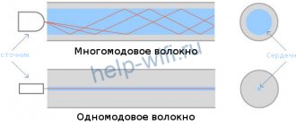
Quartz glass, which is the carrier medium of fiber-optic links, in addition to unique transmission characteristics, has another valuable property - low losses and insensitivity to electromagnetic fields. This sets it apart from conventional copper cabling systems.
This information transmission system is usually used in the construction of work facilities as external highways that unite isolated structures or buildings, as well as multi-story buildings. It can also be used as an internal carrier of a structured cabling system (SCS), however, complete SCS made entirely of fiber are less common due to the high cost of building optical communication lines.
The use of fiber-optic communication lines allows you to locally combine workplaces, provide high speed Internet downloads on all machines simultaneously, high-quality telephone communications and television reception.
Advantages of fiber optic communication lines
With proper design of the future system (this stage involves solving architectural issues, as well as choosing suitable equipment and methods of connecting support cables) and professional installation, the use of fiber-optic lines provides a number of significant advantages:
- High throughput due to high carrier frequency. The potential of one optical fiber is several terabits of information in 1 second.
- Fiber optic cable has a low noise level, which has a positive effect on its throughput and ability to transmit signals of various modulations.
- Fire safety (fire resistance). Unlike other communication systems, fiber-optic lines can be used without any restrictions in high-risk enterprises, in particular in petrochemical plants, due to the absence of sparking.
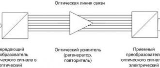
- Due to the low attenuation of the light signal, optical systems can combine working areas over significant distances (more than 100 km) without the use of additional repeaters (amplifiers).
- Information Security. Fiber-optic communications provide reliable protection against unauthorized access and interception of confidential information. This ability of optics is explained by the absence of radiation in the radio range, as well as high sensitivity to vibrations. In case of wiretapping attempts, the built-in monitoring system can turn off the channel and warn about a suspected hack. This is why fiber-optic communication lines are actively used by modern banks, research centers, law enforcement organizations and other structures that work with classified information.
- High reliability and noise immunity of the system. The fiber, being a dielectric conductor, is not sensitive to electromagnetic radiation and is not afraid of oxidation and moisture.
- Economical. Despite the fact that the creation of optical systems, due to their complexity, is more expensive than traditional SCS, in general, their owner receives real economic benefits. Optical fiber, which is made from quartz, costs about 2 times less than copper cable; in addition, when building large systems, you can save on amplifiers. If, when using a copper pair, repeaters need to be installed every few kilometers, then in a fiber-optic line this distance is at least 100 km. At the same time, the speed, reliability and durability of traditional SCS are significantly inferior to optics.
- The service life of fiber-optic lines is half a quarter of a century. After 25 years of continuous use, signal attenuation increases in the carrier system.
- If we compare copper and optical cables, then with the same bandwidth, the second one will weigh about 4 times less, and its volume, even when using protective sheaths, will be several times less than that of copper.
- Prospects. The use of fiber-optic communication lines makes it possible to easily increase the computing capabilities of local networks due to the installation of faster active equipment, without replacing communications.
Operating principle
What are the reasons for the sharp rise in popularity of high-frequency signals? Modern textbooks mention reducing the need for signal regeneration, cost, and increasing channel capacity. Soviet engineers found out, reasoning differently: copper cables, armor, screens account for 50% of the world's copper production, 25% of lead. An insufficiently known fact became the main reason for the abandonment of Nikola Tesla's sponsors of the Wardenclyffe Tower project (the name was given by the surname of the philanthropist who donated the land). A famous Serbian scientist wanted to transmit information and energy wirelessly, frightening many local owners of copper smelters. 80 years later, the picture has changed dramatically: people realized the need to save non-ferrous metals.
The material used to make the fiber is... glass. An ordinary silicate, flavored with a fair amount of property-modifying polymers. Soviet textbooks, in addition to the indicated reasons for the popularity of the new technology, name:
- Low signal attenuation, which caused a reduction in the need for regeneration.
- No sparking, therefore fire safety, zero explosion hazard.
- No short-circuiting, reduced maintenance requirements.
- Insensitive to electromagnetic interference.
- Low weight, relatively small dimensions.
Initially, fiber optic lines were supposed to connect large highways: between cities, suburbs, and automatic telephone exchanges. USSR experts called the cable revolution akin to the advent of solid-state electronics. The development of technology has made it possible to build networks that are free of leakage currents and crosstalk. A section hundreds of kilometers long is devoid of active signal regeneration methods. The length of a single-mode cable is usually 12 km, and that of a multimode cable is 4 km. The last mile is often coated with copper. Providers are accustomed to dedicating endpoints to individual users. There are no high speeds, the transceivers are cheap, the ability to simultaneously supply power to the device, and ease of use of linear modes.
Transmitter
Typical beamformers are semiconductor LEDs, including solid-state lasers. The spectral width of the signal emitted by a typical pn junction is 30-60 nm. The efficiency of the first solid-state devices barely reached 1%. The basis of connected LEDs is often the indium-gallium-arsenic-phosphorus structure. By emitting at a lower frequency (1.3 µm), the devices provide significant spectrum dispersion. The resulting dispersion greatly limits the bitrate (10-100 Mbps). Therefore, LEDs are suitable for building local network resources (distance 2-3 km).
Frequency division with multiplexing is carried out by multi-frequency diodes. Today, imperfect semiconductor structures are being actively replaced by vertical emitting lasers, which significantly improve spectral characteristics. increasing speed. The price is the same. Stimulated emission technology brings much higher powers (hundreds of mW). Coherent radiation provides an efficiency of single-mode lines of 50%. The effect of chromatic dispersion is reduced, allowing for higher bitrates.
The short charge recombination time makes it easy to modulate the radiation with high frequencies of the supply current. In addition to vertical ones, they use:
- Lasers with feedback.
- Fabry-Perot resonators.
High bit rates of long-distance communication lines are achieved by using external modulators: electro-absorption, Mach-Zehnder interferometers. External systems eliminate the need for linear frequency modulation of the supply voltage. The cut spectrum of the discrete signal is transmitted further. Additionally, other carrier coding techniques have been developed:
- Quadrature phase shift keying.
- Orthogonal frequency division multiplexing.
- Amplitude quadrature modulation.
The transmitter is formed by a digital-to-analog converter, a driver amplifier, and a Mach-Zehnder modulator. The use of high modulation formats (above 4 quadratures) and bit rates (above 32 Gbaud) reduces efficiency due to the presence of parasitic effects. Linear errors are formed by the digital-to-analog converter and the imperfection of the synchronization system. Nonlinear distortion is caused by the saturation effect of the driver amplifier, modulator. Countermeasures significantly increase speed by allowing high quadrature modulations to be used.
The procedure is carried out by digital signal processors. Old methods compensated only for the linear component. Berenger expressed the modulator with Wien series, the DAC and amplifier modeled with truncated, time-independent Volterra series. Khana suggests using a polynomial transmitter model in addition. Each time, the coefficients of the series are found using an indirect learning architecture. Dutel recorded many common variants. Phase cross-correlation and quadrature fields simulate imperfections in synchronization systems. Nonlinear effects are compensated in the same way.
Receivers
The photodetector performs the reverse conversion between light and electricity. The lion's share of solid-state receivers uses the indium-gallium-arsenic structure. Sometimes there are pin photodiodes, avalanche ones. Metal-semiconductor-metal structures are ideal for embedding regenerators and short-wave multiplexers. Optoelectric converters are often supplemented with transimpedance amplifiers and limiters that produce a digital signal. Then they practice clock recovery with phase-locked loop.
Scope of fiber optic communication lines
As mentioned above, fiber optic cables (FOC) are used to transmit signals around (between) buildings and within objects. When building external communication lines, preference is given to optical cables, and inside buildings (internal subsystems), traditional twisted pair cables are used along with them. Thus, a distinction is made between FOCs for external (outdoor cables) and internal (indoor cables) installations.
Connecting cables are a separate type: indoors they are used as connecting cords and horizontal wiring communications - to equip individual workplaces, and outside - to connect buildings.
Installation of fiber optic cable is carried out using special tools and devices.
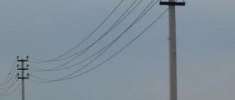
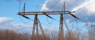
Overhead power lines
Overhead lines are those intended for the transmission and distribution of energy through wires located in the open air and supported by supports and insulators. Overhead power lines are constructed and operated in a wide variety of climatic conditions and geographic areas and are exposed to atmospheric influences (wind, ice, rain, temperature changes).
In this regard, overhead lines must be constructed taking into account atmospheric phenomena, air pollution, laying conditions (sparsely populated areas, urban areas, enterprises), etc. From the analysis of the conditions of overhead lines, it follows that the materials and designs of the lines must satisfy a number of requirements: economically acceptable cost, good electrical conductivity and sufficient mechanical strength of wire and cable materials, their resistance to corrosion and chemical influences; lines must be electrically and environmentally safe and occupy a minimum area.
Design of overhead lines. The main structural elements of overhead lines are supports, wires, lightning protection cables, insulators and linear fittings.
In terms of the design of supports, the most common are single- and double-circuit overhead lines. Up to four circuits can be constructed along the line route. Line route is the strip of land on which the line is being constructed. One circuit of a high-voltage overhead line combines three wires (sets of wires) of a three-phase line, in a low-voltage line - from three to five wires. In general, the structural part of the overhead line (Fig. 3.1) is characterized by the type of supports, span lengths, overall dimensions, phase design, and the number of insulators.
The span lengths of overhead lines l are chosen for economic reasons, since as the span length increases, the sag of the wires increases, it is necessary to increase the height of the supports H so as not to violate the permissible dimension of the line h (Fig. 3.1, b), while the number of supports and insulators will decrease by lines. Line size - the shortest distance from the bottom point of the wire to the ground (water, road surface) should be such as to ensure the safety of people and vehicles under the line.
This distance depends on the rated voltage of the line and the terrain conditions (populated, unpopulated). The distance between adjacent phases of a line depends mainly on its rated voltage. The design of an overhead line phase is mainly determined by the number of wires in the phase. If a phase is made of several wires, it is called split. The phases of high and ultra-high voltage overhead lines are split. In this case, two wires are used in one phase at 330 (220) kV, three at 500 kV, four or five at 750 kV, eight, eleven at 1150 kV.
Overhead line supports. Overhead line supports are structures designed to support wires at the required height above the ground, water, or some kind of engineering structure. In addition, if necessary, grounded steel cables are suspended from the supports to protect the wires from direct lightning strikes and associated overvoltages.
The types and designs of supports are varied. Depending on their purpose and placement on the overhead line route, they are divided into intermediate and anchor. The supports differ in material, design and method of fastening and tying up wires. Depending on the material, they are wooden, reinforced concrete and metal.
Intermediate supports are the simplest, used to support wires on straight sections of the line. They are the most common; their share on average is 80-90% of the total number of overhead line supports. The wires are attached to them using supporting (suspended) garlands of insulators or pin insulators. In normal mode, intermediate supports are loaded mainly from the own weight of wires, cables and insulators; suspended garlands of insulators hang vertically.
Anchor supports are installed in places where wires are rigidly fastened; they are divided into end, corner, intermediate and special. Anchor supports designed for longitudinal and transverse components of tension of wires (tension garlands of insulators are located horizontally) experience the greatest loads, so they are much more complex and more expensive than intermediate ones; their number on each line should be minimal.
In particular, end and corner supports installed at the end or at the turn of the line experience constant tension of wires and cables: one-sided or along the resultant of the angle of rotation; intermediate anchors installed on long straight sections are also designed for one-sided tension that may occur when part of the wires in the span adjacent to the support breaks.
Special supports are of the following types: transitional - for large spans of crossing rivers and gorges; branch lines - for making branches from the main line; transpositional - to change the order of the wires on the support.
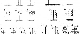
Along with the purpose (type), the design of the support is determined by the number of overhead line circuits and the relative arrangement of the wires (phases). The supports (and lines) are made in a single- or double-circuit version, while the wires on the supports can be placed in a triangle, horizontally, reverse “Christmas tree” and hexagon or “barrel” (Fig. 3.2).
The asymmetrical arrangement of phase wires in relation to each other (Fig. 3.2) determines the dissimilarity of inductances and capacitances of different phases. To ensure the symmetry of the three-phase system and phase alignment of reactive parameters on long lines (more than 100 km) with a voltage of 110 kV and higher, the wires in the circuit are rearranged (transposed) using appropriate supports.
With a full cycle of transposition, each wire (phase) uniformly along the length of the line sequentially occupies the position of all three phases on the support (Fig. 3.3).
Wooden supports (Fig. 3.4) are made of pine or larch and are used on lines with voltages up to 110 kV in forested areas, nowadays less and less. The main elements of the supports are stepsons (attachments) 1, racks 2, traverses 3, braces 4, sub-traverse beams 6 and crossbars 5. The supports are easy to manufacture, cheap, and easy to transport. Their main drawback is their fragility due to wood rotting, despite its treatment with an antiseptic. The use of reinforced concrete stepsons (attachments) increases the service life of supports to 20-25 years.
Reinforced concrete supports (Fig. 3.5) are most widely used on lines with voltages up to 750 kV. They can be free-standing (intermediate) or with guys (anchor). Reinforced concrete supports are more durable than wooden ones, easy to use, and cheaper than metal ones.
Metal (steel) supports (Fig. 3.6) are used on lines with voltages of 35 kV and above. The main elements include racks 1, traverses 2, cable racks 3, guys 4 and foundation 5. They are strong and reliable, but quite metal-intensive, occupy a large area, require special reinforced concrete foundations for installation and must be painted during operation to protect them from corrosion.
Metal supports are used in cases where it is technically difficult and uneconomical to construct overhead lines on wooden and reinforced concrete supports (crossing rivers, gorges, making taps from overhead lines, etc.).
In Russia, unified metal and reinforced concrete supports of various types have been developed for overhead lines of all voltages, which allows them to be mass-produced, speeding up and reducing the cost of the construction of lines.
Overhead wires.
Wires are designed to transmit electricity. Along with good electrical conductivity (possibly lower electrical resistance), sufficient mechanical strength and corrosion resistance must satisfy the conditions of efficiency. For this purpose, wires made of the cheapest metals are used - aluminum, steel, and special aluminum alloys. Although copper is the most conductive, copper wires, due to their significant cost and need for other purposes, are not used in new lines.
Their use is allowed in contact networks and in networks of mining enterprises.
On overhead lines, mostly uninsulated (bare) wires are used. According to their design, the wires can be single- or multi-wire, hollow (Fig. 3.7). Single-wire, predominantly steel wires, are used to a limited extent in low-voltage networks. To give flexibility and greater mechanical strength, wires are made multi-wire from one metal (aluminum or steel) and from two metals (combined) - aluminum and steel. Steel in the wire increases mechanical strength.
Based on the conditions of mechanical strength, aluminum wires of grades A and AKP (Fig. 3.7) are used on overhead lines with voltages up to 35 kV. Overhead lines 6–35 kV can also be made with steel-aluminum wires, and above 35 kV lines are installed exclusively with steel-aluminum wires.
Steel-aluminum wires have strands of aluminum wires around a steel core. The cross-sectional area of the steel part is usually 4-8 times smaller than the aluminum part, but steel absorbs about 30-40% of the total mechanical load; such wires are used on lines with long spans and in areas with more severe climatic conditions (with a thicker ice wall).
The grade of steel-aluminum wires indicates the cross-section of the aluminum and steel parts, for example, AS 70/11, as well as data on anti-corrosion protection, for example, ASKS, ASKP - the same wires as AC, but with a core filler (C) or the entire wire ( P) anti-corrosion lubricant; ASK is the same wire as AC, but with a core covered with plastic film. Wires with anti-corrosion protection are used in areas where the air is contaminated with impurities that are destructive to aluminum and steel. The cross-sectional areas of wires are standardized by the State Standard.
Increasing the diameters of wires while maintaining the same consumption of conductor material can be done by using wires filled with dielectric and hollow wires (Fig. 3.7, d, e). This use reduces coronation losses (see clause 2.2). Hollow wires are used mainly for busbars of switchgears 220 kV and above.
Wires made of aluminum alloys (AN - non-heat-treated, AZh - heat-treated) have greater mechanical strength compared to aluminum and almost the same electrical conductivity. They are used on overhead lines with voltages above 1 kV in areas with ice wall thickness up to 20 mm.
Overhead lines with self-supporting insulated wires with a voltage of 0.38-10 kV are increasingly used. In 380/220 V lines, the wires consist of a carrier non-insulated wire, which is neutral, three insulated phase wires, one insulated wire (of any phase) for external lighting. Phase insulated wires are wound around the supporting neutral wire (Fig. 3.8).
The supporting wire is steel-aluminum, and the phase wires are aluminum. The latter are covered with light-resistant heat-stabilized (cross-linked) polyethylene (APV type wire). The advantages of overhead lines with insulated wires over lines with bare wires include the absence of insulators on the supports, maximum use of the height of the support for hanging wires; there is no need to trim trees in the line area.
Lightning protection cables, along with spark gaps, arresters, voltage limiters and grounding devices, serve to protect the line from atmospheric overvoltages (lightning discharges). The cables are suspended above the phase wires (Fig. 3.5) on overhead lines with a voltage of 35 kV and higher, depending on the area of lightning activity and the material of the supports, which is regulated by the Electrical Installation Rules (PUE).
Galvanized steel ropes of grades C 35, C 50 and C 70 are usually used as lightning protection wires, and when using cables for high-frequency communication, steel-aluminum wires are used. Fastening of cables on all supports of overhead lines with a voltage of 220-750 kV must be done using an insulator bridged by a spark gap. On 35-110 kV lines, cables are fastened to metal and reinforced concrete intermediate supports without cable insulation.
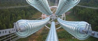
Overhead line insulators. Insulators are designed for insulating and fastening wires. They are made of porcelain and tempered glass - materials with high mechanical and electrical strength and resistance to atmospheric influences. A significant advantage of glass insulators is that if damaged, tempered glass crumbles. This makes it easier to locate damaged insulators on the line.
According to their design and method of fastening to the support, insulators are divided into pin and suspended. Pin insulators (Fig. 3.9, a, b) are used for lines with voltages up to 10 kV and rarely (for small sections) 35 kV. They are attached to the supports using hooks or pins. Suspended insulators (Fig. 3.9, c) are used on overhead lines with a voltage of 35 kV and above. They consist of a porcelain or glass insulating part 1, a cap made of malleable cast iron 2, a metal rod 3 and a cement binder 4.
Insulators are assembled into garlands (Fig. 3.9, d): supporting ones on intermediate supports and tension ones on anchor ones. The number of insulators in a garland depends on the voltage, type and material of supports, and atmospheric pollution. For example, in a 35 kV line there are 3-4 insulators, 220 kV - 12-14; on lines with wooden supports, which have increased lightning resistance, the number of insulators in the garland is one less than on lines with metal supports; in tension garlands operating in the most difficult conditions, 1-2 more insulators are installed than in supporting ones.
Insulators using polymer materials have been developed and undergo experimental industrial testing. They are a core element made of fiberglass, protected by a coating with ribs made of fluoroplastic or silicone rubber. Rod insulators, compared to suspended insulators, have lower weight and cost, and higher mechanical strength than those made from tempered glass. The main problem is to ensure the possibility of their long-term (more than 30 years) operation.
Linear fittings are designed to secure wires to insulators and cables to supports and contain the following main elements: clamps, connectors, spacers, etc. (Fig. 3.10).
Supporting clamps are used for hanging and securing overhead line wires on intermediate supports with limited rigidity of the embedment (Fig. 3.10, a). On anchor supports, tension garlands and tension clamps are used for rigid fastening of wires - tension and wedge (Fig. 3.10, b, c) . Coupling fittings (earrings, ears, brackets, rocker arms) are designed for hanging garlands on supports. The supporting garland (Fig. 3.10, d) is secured to the traverse of the intermediate support using earring 1, which is inserted with the other side into the cap of the upper suspension insulator 2. Eyelet 3 is used to attach the garland of supporting clamp 4 to the lower insulator.
Distance spacers (Fig. 3.10, e), installed in the spans of lines 330 kV and above with split phases, prevent overlap, collision and twisting of individual phase wires. Connectors are used to connect individual sections of wire using oval or pressing connectors (Fig. 3.10, f, g). In oval connectors, the wires are either twisted or crimped; in pressed connectors used to connect steel-aluminum wires of large cross-sections, the steel and aluminum parts are pressed separately.
The result of the development of technology for transmitting energy over long distances is various variants of compact power lines, characterized by a smaller distance between phases and, as a consequence, smaller inductive reactances and line path width (Fig. 3.11). When using “female-type” supports (Fig. 3.11, a), reducing the distance is achieved by locating all phase split structures inside the “encompassing portal”, or on one side of the support column (Fig. 3.11, b). Phase proximity is ensured using interphase insulating spacers. Various options for compact lines with non-traditional layouts of split-phase wires have been proposed (Fig. 3.11, c-i).
In addition to reducing the route width per unit of transmitted power, compact lines can be created to transmit increased powers (up to 8-10 GW); such lines cause a lower electric field strength at ground level and have a number of other technical advantages.
Compact lines also include controlled self-compensating lines and controlled lines with an unconventional split-phase configuration. They are double-circuit lines in which the like phases of different circuits are shifted in pairs. In this case, voltages are applied to the circuits, shifted by a certain angle. Due to the regime change using special phase shift angle devices, the parameters of the lines are controlled.
Overhead lines are those intended for the transmission and distribution of energy through wires located in the open air and supported by supports and insulators. Overhead power lines are constructed and operated in a wide variety of climatic conditions and geographic areas and are exposed to atmospheric influences (wind, ice, rain, temperature changes).
In this regard, overhead lines must be constructed taking into account atmospheric phenomena, air pollution, laying conditions (sparsely populated areas, urban areas, enterprises), etc. From the analysis of the conditions of overhead lines, it follows that the materials and designs of the lines must satisfy a number of requirements: economically acceptable cost, good electrical conductivity and sufficient mechanical strength of wire and cable materials, their resistance to corrosion and chemical influences; lines must be electrically and environmentally safe and occupy a minimum area.
Design of overhead lines. The main structural elements of overhead lines are supports, wires, lightning protection cables, insulators and linear fittings.
In terms of the design of supports, the most common are single- and double-circuit overhead lines. Up to four circuits can be constructed along the line route. Line route is the strip of land on which the line is being constructed. One circuit of a high-voltage overhead line combines three wires (sets of wires) of a three-phase line, in a low-voltage line - from three to five wires. In general, the structural part of the overhead line (Fig. 3.1) is characterized by the type of supports, span lengths, overall dimensions, phase design, and the number of insulators.
The span lengths of overhead lines l are chosen for economic reasons, since as the span length increases, the sag of the wires increases, it is necessary to increase the height of the supports H so as not to violate the permissible dimension of the line h (Fig. 3.1, b), while the number of supports and insulators will decrease by lines. Line size - the shortest distance from the bottom point of the wire to the ground (water, road surface) should be such as to ensure the safety of people and vehicles under the line.
This distance depends on the rated voltage of the line and the terrain conditions (populated, unpopulated). The distance between adjacent phases of a line depends mainly on its rated voltage. The design of an overhead line phase is mainly determined by the number of wires in the phase. If a phase is made of several wires, it is called split. The phases of high and ultra-high voltage overhead lines are split. In this case, two wires are used in one phase at 330 (220) kV, three at 500 kV, four or five at 750 kV, eight, eleven at 1150 kV.
Overhead line supports. Overhead line supports are structures designed to support wires at the required height above the ground, water, or some kind of engineering structure. In addition, if necessary, grounded steel cables are suspended from the supports to protect the wires from direct lightning strikes and associated overvoltages.
The types and designs of supports are varied. Depending on their purpose and placement on the overhead line route, they are divided into intermediate and anchor. The supports differ in material, design and method of fastening and tying up wires. Depending on the material, they are wooden, reinforced concrete and metal.
Intermediate supports are the simplest, used to support wires on straight sections of the line. They are the most common; their share on average is 80-90% of the total number of overhead line supports. The wires are attached to them using supporting (suspended) garlands of insulators or pin insulators. In normal mode, intermediate supports are loaded mainly from the own weight of wires, cables and insulators; suspended garlands of insulators hang vertically.
Anchor supports are installed in places where wires are rigidly fastened; they are divided into end, corner, intermediate and special. Anchor supports designed for longitudinal and transverse components of tension of wires (tension garlands of insulators are located horizontally) experience the greatest loads, so they are much more complex and more expensive than intermediate ones; their number on each line should be minimal.
In particular, end and corner supports installed at the end or at the turn of the line experience constant tension of wires and cables: one-sided or along the resultant of the angle of rotation; intermediate anchors installed on long straight sections are also designed for one-sided tension that may occur when part of the wires in the span adjacent to the support breaks.
Special supports are of the following types: transitional - for large spans of crossing rivers and gorges; branch lines - for making branches from the main line; transpositional - to change the order of the wires on the support.
Along with the purpose (type), the design of the support is determined by the number of overhead line circuits and the relative arrangement of the wires (phases). The supports (and lines) are made in a single- or double-circuit version, while the wires on the supports can be placed in a triangle, horizontally, reverse “Christmas tree” and hexagon or “barrel” (Fig. 3.2).
The asymmetrical arrangement of phase wires in relation to each other (Fig. 3.2) determines the dissimilarity of inductances and capacitances of different phases. To ensure the symmetry of the three-phase system and phase alignment of reactive parameters on long lines (more than 100 km) with a voltage of 110 kV and higher, the wires in the circuit are rearranged (transposed) using appropriate supports.
With a full cycle of transposition, each wire (phase) uniformly along the length of the line sequentially occupies the position of all three phases on the support (Fig. 3.3).
Wooden supports (Fig. 3.4) are made of pine or larch and are used on lines with voltages up to 110 kV in forested areas, nowadays less and less. The main elements of the supports are stepsons (attachments) 1, racks 2, traverses 3, braces 4, sub-traverse beams 6 and crossbars 5. The supports are easy to manufacture, cheap, and easy to transport. Their main drawback is their fragility due to wood rotting, despite its treatment with an antiseptic. The use of reinforced concrete stepsons (attachments) increases the service life of supports to 20-25 years.
Reinforced concrete supports (Fig. 3.5) are most widely used on lines with voltages up to 750 kV. They can be free-standing (intermediate) or with guys (anchor). Reinforced concrete supports are more durable than wooden ones, easy to use, and cheaper than metal ones.
Metal (steel) supports (Fig. 3.6) are used on lines with voltages of 35 kV and above. The main elements include racks 1, traverses 2, cable racks 3, guys 4 and foundation 5. They are strong and reliable, but quite metal-intensive, occupy a large area, require special reinforced concrete foundations for installation and must be painted during operation to protect them from corrosion.
Metal supports are used in cases where it is technically difficult and uneconomical to construct overhead lines on wooden and reinforced concrete supports (crossing rivers, gorges, making taps from overhead lines, etc.).
In Russia, unified metal and reinforced concrete supports of various types have been developed for overhead lines of all voltages, which allows them to be mass-produced, speeding up and reducing the cost of the construction of lines.
Overhead wires.
Wires are designed to transmit electricity. Along with good electrical conductivity (possibly lower electrical resistance), sufficient mechanical strength and corrosion resistance must satisfy the conditions of efficiency. For this purpose, wires made of the cheapest metals are used - aluminum, steel, and special aluminum alloys. Although copper is the most conductive, copper wires, due to their significant cost and need for other purposes, are not used in new lines.
Their use is allowed in contact networks and in networks of mining enterprises.
On overhead lines, mostly uninsulated (bare) wires are used. According to their design, the wires can be single- or multi-wire, hollow (Fig. 3.7). Single-wire, predominantly steel wires, are used to a limited extent in low-voltage networks. To give flexibility and greater mechanical strength, wires are made multi-wire from one metal (aluminum or steel) and from two metals (combined) - aluminum and steel. Steel in the wire increases mechanical strength.
Based on the conditions of mechanical strength, aluminum wires of grades A and AKP (Fig. 3.7) are used on overhead lines with voltages up to 35 kV. Overhead lines 6–35 kV can also be made with steel-aluminum wires, and above 35 kV lines are installed exclusively with steel-aluminum wires.
Steel-aluminum wires have strands of aluminum wires around a steel core. The cross-sectional area of the steel part is usually 4-8 times smaller than the aluminum part, but steel absorbs about 30-40% of the total mechanical load; such wires are used on lines with long spans and in areas with more severe climatic conditions (with a thicker ice wall).
The grade of steel-aluminum wires indicates the cross-section of the aluminum and steel parts, for example, AS 70/11, as well as data on anti-corrosion protection, for example, ASKS, ASKP - the same wires as AC, but with a core filler (C) or the entire wire ( P) anti-corrosion lubricant; ASK is the same wire as AC, but with a core covered with plastic film. Wires with anti-corrosion protection are used in areas where the air is contaminated with impurities that are destructive to aluminum and steel. The cross-sectional areas of wires are standardized by the State Standard.
Increasing the diameters of wires while maintaining the same consumption of conductor material can be done by using wires filled with dielectric and hollow wires (Fig. 3.7, d, e). This use reduces coronation losses (see clause 2.2). Hollow wires are used mainly for busbars of switchgears 220 kV and above.
Wires made of aluminum alloys (AN - non-heat-treated, AZh - heat-treated) have greater mechanical strength compared to aluminum and almost the same electrical conductivity. They are used on overhead lines with voltages above 1 kV in areas with ice wall thickness up to 20 mm.
Overhead lines with self-supporting insulated wires with a voltage of 0.38-10 kV are increasingly used. In 380/220 V lines, the wires consist of a carrier non-insulated wire, which is neutral, three insulated phase wires, one insulated wire (of any phase) for external lighting. Phase insulated wires are wound around the supporting neutral wire (Fig. 3.8).
The supporting wire is steel-aluminum, and the phase wires are aluminum. The latter are covered with light-resistant heat-stabilized (cross-linked) polyethylene (APV type wire). The advantages of overhead lines with insulated wires over lines with bare wires include the absence of insulators on the supports, maximum use of the height of the support for hanging wires; there is no need to trim trees in the line area.
Lightning protection cables, along with spark gaps, arresters, voltage limiters and grounding devices, serve to protect the line from atmospheric overvoltages (lightning discharges). The cables are suspended above the phase wires (Fig. 3.5) on overhead lines with a voltage of 35 kV and higher, depending on the area of lightning activity and the material of the supports, which is regulated by the Electrical Installation Rules (PUE).
Galvanized steel ropes of grades C 35, C 50 and C 70 are usually used as lightning protection wires, and when using cables for high-frequency communication, steel-aluminum wires are used. Fastening of cables on all supports of overhead lines with a voltage of 220-750 kV must be done using an insulator bridged by a spark gap. On 35-110 kV lines, cables are fastened to metal and reinforced concrete intermediate supports without cable insulation.
Overhead line insulators. Insulators are designed for insulating and fastening wires. They are made of porcelain and tempered glass - materials with high mechanical and electrical strength and resistance to atmospheric influences. A significant advantage of glass insulators is that if damaged, tempered glass crumbles. This makes it easier to locate damaged insulators on the line.
According to their design and method of fastening to the support, insulators are divided into pin and suspended. Pin insulators (Fig. 3.9, a, b) are used for lines with voltages up to 10 kV and rarely (for small sections) 35 kV. They are attached to the supports using hooks or pins. Suspended insulators (Fig. 3.9, c) are used on overhead lines with a voltage of 35 kV and above. They consist of a porcelain or glass insulating part 1, a cap made of malleable cast iron 2, a metal rod 3 and a cement binder 4.
Insulators are assembled into garlands (Fig. 3.9, d): supporting ones on intermediate supports and tension ones on anchor ones. The number of insulators in a garland depends on the voltage, type and material of supports, and atmospheric pollution. For example, in a 35 kV line there are 3-4 insulators, 220 kV - 12-14; on lines with wooden supports, which have increased lightning resistance, the number of insulators in the garland is one less than on lines with metal supports; in tension garlands operating in the most difficult conditions, 1-2 more insulators are installed than in supporting ones.
Insulators using polymer materials have been developed and undergo experimental industrial testing. They are a core element made of fiberglass, protected by a coating with ribs made of fluoroplastic or silicone rubber. Rod insulators, compared to suspended insulators, have lower weight and cost, and higher mechanical strength than those made from tempered glass. The main problem is to ensure the possibility of their long-term (more than 30 years) operation.
Linear fittings are designed to secure wires to insulators and cables to supports and contain the following main elements: clamps, connectors, spacers, etc. (Fig. 3.10).
Supporting clamps are used for hanging and securing overhead line wires on intermediate supports with limited rigidity of the embedment (Fig. 3.10, a). On anchor supports, tension garlands and tension clamps are used for rigid fastening of wires - tension and wedge (Fig. 3.10, b, c) . Coupling fittings (earrings, ears, brackets, rocker arms) are designed for hanging garlands on supports. The supporting garland (Fig. 3.10, d) is secured to the traverse of the intermediate support using earring 1, which is inserted with the other side into the cap of the upper suspension insulator 2. Eyelet 3 is used to attach the garland of supporting clamp 4 to the lower insulator.
Distance spacers (Fig. 3.10, e), installed in the spans of lines 330 kV and above with split phases, prevent overlap, collision and twisting of individual phase wires. Connectors are used to connect individual sections of wire using oval or pressing connectors (Fig. 3.10, f, g). In oval connectors, the wires are either twisted or crimped; in pressed connectors used to connect steel-aluminum wires of large cross-sections, the steel and aluminum parts are pressed separately.
The result of the development of technology for transmitting energy over long distances is various variants of compact power lines, characterized by a smaller distance between phases and, as a consequence, smaller inductive reactances and line path width (Fig. 3.11). When using “female-type” supports (Fig. 3.11, a), reducing the distance is achieved by locating all phase split structures inside the “encompassing portal”, or on one side of the support column (Fig. 3.11, b). Phase proximity is ensured using interphase insulating spacers. Various options for compact lines with non-traditional layouts of split-phase wires have been proposed (Fig. 3.11, c-i).
In addition to reducing the route width per unit of transmitted power, compact lines can be created to transmit increased powers (up to 8-10 GW); such lines cause a lower electric field strength at ground level and have a number of other technical advantages.
Compact lines also include controlled self-compensating lines and controlled lines with an unconventional split-phase configuration. They are double-circuit lines in which the like phases of different circuits are shifted in pairs. In this case, voltages are applied to the circuits, shifted by a certain angle. Due to the regime change using special phase shift angle devices, the parameters of the lines are controlled.
FOCL connection technologies
The length of fiber-optic communication lines can reach hundreds of kilometers (for example, when building communications between cities), while the standard length of optical fibers is several kilometers (including because working with too long lengths is in some cases very inconvenient). Thus, when constructing a route, it is necessary to solve the problem of splicing individual optical fibers.
There are two types of connections: detachable and permanent. In the first case, optical connectors are used for connection (this is associated with additional financial costs, and, in addition, with a large number of intermediate connectors, optical losses increase).
For permanent connection of local sections (installation of routes), mechanical connectors, adhesive splicing and welding of fibers are used. In the latter case, machines for splicing optical fibers are used. Preference is given to one method or another taking into account the purpose and conditions of use of the optics.
Optical fiber welding
The most common technology today is fiber welding technology.
Optical fiber splicing machines
The highest quality connection with minimal losses is ensured by welding fibers. This method is used to create high-speed fiber optic lines. During welding, the ends of the light guide melt; for this, a gas burner, an electric charge, or laser radiation can be used as a source of thermal energy.
Each method has its own advantages. Laser welding, due to the absence of impurities, allows you to obtain the purest compounds. Gas torches are typically used to permanently splice multimode fibers. The most common is electric welding, which provides high speed and quality of work. The melting time of different types of optical fibers differs.
For welding work, special tools and expensive welding equipment are used - automatic or semi-automatic. Modern welding machines allow you to control the quality of welding, as well as test tensile joints. Advanced models are equipped with programs that allow you to optimize the welding process for a specific type of optical fiber.
After fusion, the joint is protected by tightly fitted tubes, which provide additional mechanical protection.
Optical fiber bonding
The technology of fiber gluing is used less frequently, mainly in the production of patch cords and pigtails. It includes several technological operations. In particular, before connection, optical cables undergo preliminary preparation: in places of future connections, the protective coating and excess fiber are removed (the prepared area is cleaned of hydrophobic composition). To securely fix the light guide in the connector, epoxy glue is used, which fills the internal space of the connector (it is inserted into the connector body using a syringe or dispenser). To harden and dry the glue, a special oven is used that can create a temperature of 100 degrees. WITH.
Once the glue has cured, excess fiber is removed and the connector tip is ground and polished (chip quality is of utmost importance). To ensure high accuracy, these works are monitored using a 200x microscope. Polishing can be done by hand or using a polishing machine.
Mechanical connection of optical fibers
Another method of splicing fiber optic elements into a single fiber optic line is a mechanical connection. This method provides less cleanliness of the connection than welding, however, the signal attenuation in this case is still less than when using optical connectors.
The advantage of this method over others is that simple devices are used to carry out the work (for example, an assembly table), which allow work to be carried out in hard-to-reach places or inside small structures.
Mechanical splicing involves the use of special connectors - so-called splices. There are several types of mechanical connectors, which are an elongated structure with a channel for entering and fixing spliced optical fibers. The fixation itself is ensured using the latches provided by the design. After connection, the splices are additionally protected by couplings or boxes.
Mechanical connectors can be used repeatedly. In particular, they are used during repair or restoration work on the line.
Fibers
The type of optical fibers, as well as their number (of which there are never too many), are the main characteristics of the communication line.
| Characteristic | Multimode fiber OM1* | Multimode fiber OM2* | Multimode fiber OM3 | Multimode fiber OM4 | Single-mode fiber OS2** |
| Core/shell diameter, µm | 62,5/125 | 50/125 62.5/125 (less common) | 50/125 | 50/125 | 9/125 |
| Shell color coding (recommended) | orange | orange | sea wave (aqua) | sea wave (aqua) or magenta | yellow |
| Maximum distance*, m | 1000Base-SX @850nm — 220 1000Base-LX @1310nm — 550 10GBase-SR @850nm — 33 | 1000Base-SX @850nm — 550 1000Base-LX @1310nm — 550 10GBase-SR @850nm — 82 | 1000Base-SX @850nm — 550*** 1000Base-LX @1310nm — 550 10GBase-SR @850nm — 300 40GBase-SR4/100GBASE-SR10 @850nm — 100 | 1000Base-SX @850nm — 550*** 1000Base-LX @1310nm — 550 10GBase-SR @850nm — 400 40GBase-SR4/100GBASE-SR10 @850nm — 150 | 1000Base-LX @1310nm — 5000**** 1000BASE‑BX10 @1310/1500nm- 10000 40GBase-LR4/100GBase-LR4 @1310nm — 10000 |
* Fibers of the OM1 and OM2 types are considered obsolete (implying the use of only LED transmitters), although they still provide data transmission up to 10 Gbit/s, albeit on short lines; ** OS1 type fibers had several varieties and already about 10 years ago, many manufacturers had them corresponding to the current OS2. Currently, OS1 is practically unheard of; *** Manufacturers of SFP modules often claim a longer range - about 1 km; **** Manufacturers of SFP modules often claim a longer range – 10 km.
Small comments on the table:
- Next to the standard, the wavelength is indicated through @. Optical fibers have so-called “transparency windows” in which attenuation is minimal (these are 850 nm, 1310 nm and 1550 nm, but fiber manufacturers do not stand still and increase their number);
- Although there are many cable manufacturers, only a small number of companies produce fiber: the most famous are, of course, Corning (yes, it is their Gorilla Glass that most people know) and Fujikura, but it is worth mentioning also ofs, Hitachi Cable, Sumitomo Electric and Draka NK Cables ;
- OM1-OM4 are the designations for multimode cables adopted in ISO 11801 and they differ from those adopted in the IEC 60793-2-10 and TIA/EIA standards. But basically the designations on the websites of manufacturers and suppliers are indicated precisely in accordance with ISO11801;
- The OM5 type cable appeared (in November 2022), but it is still poorly distributed and how “survivable” it will be is not clear.
Choosing the type of fiber is a complex task, in which, as a rule, there are two participants - the “cable guy” (SCS) and the “networker”, since the price of the line will consist of the cost of the cable line and SFP modules. If multimode fibers are usually used for administrative buildings, then single-mode fibers are used for “long” distances and on the territory of factories. It is according to the selected type of fiber that all other “components” are selected.
Well, from the trash category: over short distances you can use a cable with multimode fibers together with single-mode transmitters and patch cords. But it's better not to do that