Author of the article
Pavel Yastremsky
Head of IT department. In the field for more than 10 years, he develops his own software.
Ask a Question
The ubiquity of fiber optics was a consequence of the development of the Ethernet standard, which was born back in 1973. At that time, the data transfer speed in computer networks reached a maximum of 2.94 Mbit/s. Today this figure seems simply ridiculous and does not meet the requirements of a modern Internet user. The development of the 802.3 standard resulted in the emergence of 1000BASE-X, built on a fundamentally different information transfer technology.
Definition
Fiber optic cable is part of the passive components of FOCL (Fiber Optic Communication Line). It consists of light-carrying elements protected by an outer shell. The segment length can reach 100 km without loss or weakening of the signal. Using a coupling, the segments are connected to each other. The luminous flux is used to transmit a signal along the channel. It is generated by a laser and transformed by an electrical regenerator and a photodetector.
Optical cable structure
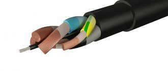
Regardless of whether quartz or polymer material is used, the cable structure is the same. It is formed by:
- Core. Responsible for spreading the light beam along the length of the cable. The diameter directly affects the available “hit” area of the light beam, and therefore the ability to supply radiation for high-quality signal delivery. The refractive index in the core is 1.48.
- Inner shell . Responsible for reflecting the light beam and “adjusting” its trajectory. In other words, it prevents the beam from leaving the core. The higher the reflective power of the shell, the faster the beam propagates, the signal is transmitted and the less it is lost.
- External cladding. This is a buffer from external influences. Protects internal cable components from environmental factors, including chemical and mechanical influences. The maximum permissible skin thickness does not exceed 250 microns.
Advantages and disadvantages
Optical fiber has a number of undeniable advantages over twisted pair:
- high bandwidth of optical fiber compared to copper. Google built the US-Japan highway with a maximum transmission speed of 600 Tbps;
- lower power losses and the ability to transmit data over long distances;
- resistance to electromagnetic interference;
- the length of a network segment using single-mode fiber can reach 100 kilometers;
- optics are lighter, thinner and take up less space;
- transmitted information is very difficult to intercept, since the cable does not produce electromagnetic energy;
- oxidation resistance;
- absence of precious metals in the design, resulting in low cost.
Among the disadvantages it is worth noting:
- installation complexity requires special equipment;
- due to improper installation, when bending the wire, the optical fiber may break or the signal may lose intensity at an angle;
- To test data transmission over a fiber optic cable, special devices are required.
So which is better - optics or copper?
Nowadays, any large and even medium-sized Internet provider uses optical fiber in a number of segments of its networks. And vice versa: no matter how the provider lures you with a connection to the “fastest new generation system,” certain sections of its networks are traditional copper cable. It’s just that the rules are dictated by environmental conditions (in some places they are more suitable for copper, and in others for optics) and economic feasibility, and marketing is marketing.
No one can say for sure what type of highway the providers “The Bronze Horseman” and “Optical Illusion” connected your home to, so we will assume that their offers differ only in the way they connect subscribers inside apartments.
The table below compares the properties of fiber optics and twisted pair:
| Optical fiber | Copper twisted pair | |
| Theoretically achievable communication speed | OS1 – 40 Gbps OS2– 100 Gbit/s OM3 and OM4 – 100 Gbit/s | Up to 10 Gbps for Category 6 and 7 cables. |
| Maximum continuous line length | OS1 – 100 km OS2 – 40 km OM3 – 300 m OM4 – 125 m. | 100 m |
| Physical properties of the cable | Thin, fragile | Thick, flexible |
| Exposure to external influences | Excessive bending, pressure, certain types of radiation | Electromagnetic interference, atmospheric electricity, corrosive chemical environments, fire, unauthorized connection to read data |
| Compatibility with client equipment | Requires the purchase of special adapters | Compatible with any device equipped with RJ-45 jacks |
| Service | Requires special equipment and training | Requires minimal skills and knowledge |
| Price | High | Low |
Let's summarize:
- A fiber optic line is up to 10 times faster and has a much longer range than twisted pair, it is not affected by interference from electrical equipment and power lines, is durable and strong, does not burn, and does not lose its properties from moisture, acids and alkalis. Does not allow spy tapping or eavesdropping via inductive connection.
- A fiber-optic network is easier to disguise in the interior; it does not require the installation of wide, unaesthetic cable channels.
- Fiber optics is, although flexible, glass, and any glass can crack and crumble. Therefore, installation and modernization of such a network requires great care. If damaged twisted pair can be cut and connected by simple twisting, then to restore broken optics you need a special welding machine and the ability to handle it. And sometimes even minor damage to a fiber optic line requires its complete replacement.
- The main advantage of twisted pair is its low cost and ease of use. Most likely, you will not be charged any extra money for connecting to the Internet via a copper cable, but you will have to pay for optics, because they are expensive. A twisted pair cable with a universal connector can be immediately plugged into a computer - and the Internet will appear on it. For optics, you will again have to fork out for a special socket, modem (ONT terminal or router), and network adapters. And this is also not cheap.
Purely fiber optic networks inside houses and apartments are still very rare; most often they are made hybrid - partly optical, partly copper wire, partly wireless. The optics are usually connected only to the modem, and the end devices - computers, smartphones, smart TVs, etc. receive the Internet over the same twisted pair cable or Wi-Fi, because they are not equipped with light signal decoding modules. This means that no matter what super speeds your provider promises you, slow network segments will reduce it to nothing.
So, your choice is “The Bronze Horseman” if:
- You don't want to overpay for something you probably won't get. If your devices that consume Internet traffic operate on outdated Ethernet or Wi-Fi protocols, then optics will not make them faster.
- You often move your computer from place to place, you have a dog that likes to chew wires, or small children who grab everything. And if the cable is damaged, it’s easier for you to fix it yourself than to pay a technician.
It is better for you to become a client of Optical Illusion if:
- You are for everything new against everything old. Fiber optics is the technology of the future and therefore worthy of investment. And even if it is not friendly with every device, we can expect that soon the manufacturers of the latter will come to their senses and equip their products with fiber-optic support. After all, consumers want this and are ready to invest.
- Finances are not a problem for you. You have modern technology that supports the latest wired and wireless communication protocols, and you are ready to make it “take the maximum height.”
- You need speed and that's it.
- Network security in terms of possible data leakage is your everything.
Principle of operation
The fiber optic cable is based on glass light guides. These are unique routes for transporting light rays from the source to the receiver. Electrons move along the familiar copper conductor, which is still widely used in local networks to this day. Information is encoded by ones and zeros: if there is an electrical impulse, then it is transformed by the network card into the value “1”, and vice versa, if it is not there - into “0”.
With optics the situation looks approximately the same. Its beams—modes—move in it at the speed of light. Their presence determines the transmitted bit of information, only at a much higher speed (more than 10 Gbit/s).
To send a light signal, a laser is used, the beam of which is directed into the core of the cable. Using a system of mirrors, it is shielded, which allows it to pass through bends and irregularities of the channel. The end of the light path is the end equipment, such as a media converter or PON-enabled router.
Its task is to convert an optical signal into an electrical one and vice versa. A standard twisted pair cable is laid from it and connected to network equipment, for example, a home router.
Areas of use
The first thing that comes to mind when you think of fiber optic cable is the Internet. All well-known providers have replaced their copper communications with high-speed optics. This made it possible to increase the channel capacity necessary for transmitting Internet traffic, organizing IP telephony, television and dedicated services.
In general, the entire World Wide Web was built with the help of FOC. Its networks stretch from the coast of the United States across the globe in the form of underwater communications. The fragile cable is protected by thick-walled insulation, and it is laid using special ships under the ground at the very bottom of the ocean.
This technology is becoming increasingly popular in the construction of local networks. This is especially true for country houses where there is no access to the network of large providers. There is a practice of erecting towers with Wi-Fi guns, from which optics extend to private properties, thus allowing you to connect to the Internet far from the city.
In addition, optical fiber is used in the following areas:
- industrial control systems;
- aviation systems;
- military command, control and communications systems;
- sensors – optics can be used to deliver light from a distant source to a sensor to obtain information about pressure, temperature or other information;
- Power Delivery – Optical fibers can provide exceptionally high levels of power for applications such as laser cutting, welding, marking and drilling;
- illumination - a bundle of fibers assembled together with a light source at one end can illuminate hard-to-reach areas - for example, inside the human body, when combined with an endoscope. They can also be used as an exhibition sign or decorative lighting.
Construction and materials
Having decided what optical fiber is, let’s move on to a description of its structure. To better understand the structure of optical fiber, consider the process of its production:
- heated quartz sand is pulled through a scanner, which checks the diameter of the resulting thread;
- then into the cooling chamber;
- and finally into a bath of polymer, which adheres and forms an outer protective layer;
- at the end of the vertical conveyor there is a reel onto which the cooled fiber is wound at a speed of 3 km/s;
- it is transported to the factory, where each thread is dyed so that they can then be distinguished depending on the data transmission channel;
- on a special machine, bundles are formed from them, which are then sealed into a polyethylene casing;
- the bundles are sandwiched with a fiberglass reinforcement rod and then packaged in outer insulation. This is how the structure of the fiber optic cable structure is formed.
Depending on the cable use scenario, its design features may change, but the general principle remains the same. To understand the arrangement of fiber optic cable elements, a sectional photo will be the most convenient way to demonstrate them using the most common example:
- the optical fiber core is the most fragile part of the cable;
- hydrophobic filler provides protection through shock absorption;
- this structure is surrounded by a central tube;
- the intermediate polyethylene shell provides additional protection for the core;
- as a rule, the cable contains armor (there are many varieties);
- All of the above elements are covered by an outer shell.
2. Determination of design features
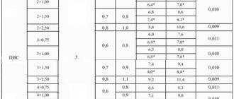
After choosing the installation conditions, it is necessary to determine the main design features depending on the customer’s requirements. They differ depending on the cable group.
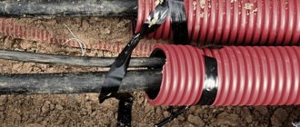
Cables for blowing into pipes
Most often, so-called PPT - protective polyethylene pipes are used for blowing. PTA is a modern alternative to the usual asbestos-cement cable sewer pipe. The PCT is laid directly into the ground, where such pipes practically perform the functions of a long-distance cable duct. Moreover, PTAs are capable of protecting the FOC even when crossing water barriers. Essentially, the PTA provides reliable protection for the fiber optic cable from mechanical damage (in particular from rodents). Therefore, the cable used to organize a fiber optic line using a PTA does not have a reservation, which makes construction cheaper.
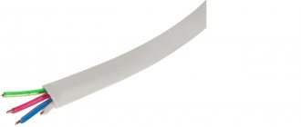
This type of cable has the simplest design (Fig. 1): there are no additional protective elements other than the sheath applied directly to the twisted core of optical modules with fibers.
The main choice within the group is to determine the required cable sizes: for blowing into ordinary plastic pipes or for blowing into micro-tubes for sewage. Microcables have a smaller weight and diameter, they are more flexible, but at the same time they are designed for a lower maximum permissible tensile load than “classic” blow-in cables.
It is important that the ratio of the cross-sectional area of the cable to the cross-sectional area of the pipe is no more than 2/3, otherwise difficulties may arise during blowing.
Rice. 1. Cable for installation in DPO (Inkab) pipes
Such a cable can be laid in tubes not only by blowing, which involves the use of an expensive blowing machine, but also by tightening the cable mechanically, using a winch. If you have such a machine at your disposal, then you can save even more on costs by using an even cheaper cable - Micro DPO.
Rice. 2. Cable for installation in Micro DPO (Inkab) pipes
Cables for installation in cable ducts
Cable sewerage is a system of underground structures consisting of pipelines and inspection devices (wells and boxes). In cable ducts, installation and replacement of cables, measurements, repair and maintenance work are carried out without opening the street covers or excavating the soil. Under such conditions, the cable is protected from mechanical damage and electrochemical corrosion.
Along with the obvious advantages, this method of laying a fiber optic cable has disadvantages: possible damage by rodents, flooding and freezing of flooded areas, possible damage to the outer shell of the fiber cable cable when pulling the cable through trays. The presence of one of the following factors or additional requirements determines the choice of a specific cable design.
Risk of damage from rodents
This is the main “danger” for the cable of this group. If there is no such threat or it is minimal, then an unarmored cable will be the best choice (see cables for blowing into pipes).
Reliable protection against rodents is ensured by the use of corrugated steel tape (Fig. 3) or steel wires in the design (see cables for laying in the ground). The number of requests for the second option (with steel wires) is extremely low.
Rice. 3. Lightweight cable for installation in cable ducts of the TOL (Inkab) brand
Dielectric structures
In rare situations, a cable is required that would protect against rodents and at the same time have dielectric properties. In this case, it is possible to use special repellents in the cable sheath that repel rodents, or to use glass fibers applied over the core and intermediate sheath of the cable. The second option, according to research, is more effective, because glass fibers are a physical barrier for rodents.
Type of optical module location
If we talk about the most common method of protection - corrugated tape, then the most popular solution here is the use of single-module structures (if the number of fibers does not exceed 24) or the use of lightweight structures with a twisted core without an intermediate sheath for multi-fiber highways.
Presence of an intermediate shell
Designs with an intermediate shell are larger and more expensive, without significantly improving performance characteristics, but they are also used by a number of consumers who choose reliable classic solutions.
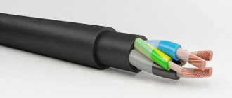
The standard sewer cable - DPL (Fig. 4) has this design. In this design, modules with optical fiber are twisted around a central power element, the entire intermodular space is filled with a hydrophobic gel, and an intermediate polyethylene shell is applied on top. Water-blocking threads are applied over the intermediate shell, then a reinforcing corrugated steel tape with a polymer coating is applied, on which the final shell of polymer material is applied.
Rice. 4. Standard cable for installation in cable ducts of the DPL (Inkab) brand
Cables for laying in the ground
The most common way to build fiber-optic trunk lines between populated areas where there is no cable duct and there is no possibility of suspending the line is laying the fiber-optic cable in the ground. This method is more expensive and time-consuming compared to constructing a line using power line supports, but it is the only possible one. Such a communication line is superior to overhead lines in terms of reliability and service life.
Read our article about the technology of laying optical cables in the ground.
Unfortunately, there are no generally accepted regulatory documents defining the required characteristics for optical cables in the ground, based on specific installation conditions. The choice of design is influenced by two main technical characteristics: resistance to crushing loads and the maximum permissible tensile load. Based on these data, the need to strengthen the structure, armor material, and type of optical module are determined.
Metal or dielectric armor
Metal armor involves the use of galvanized steel wires twisted around an optical core. This solution is classic and most popular.
Dielectric armor involves the use of fiberglass rods. This solution is more expensive, but in some cases it is the only possible one. It is used when insensitivity to electromagnetic fields is required: for installation on the territory of electrical substations, in the security zone of power lines, at the intersection of power lines, next to power cables, etc.
Strengthening the structure due to an additional layer of armor
The classic solution for laying in simple soils involves the use of one layer of armor (Fig. 5). In most cases, this is enough to provide reliable protection against mechanical stress on the cable. In the dielectric version, the cable receives a layer of armor made of fiberglass rods (Fig. 6).
Rice. 5. Standard cable for laying in the ground brand DPS (Inkab)
Rice. 6. Standard cable for laying in the ground brand DPD (Inkab)
However, in the case of cable laying in difficult soils (rocky, frozen, etc.), the design organization may decide to provide more reliable protection and use double layers of power elements (steel wires or fiberglass rods).
The layers are twisted in different directions. This provides better tensile and crush resistance characteristics compared to structures based on a single layer.
Optical module type
The central optical module is a more economical solution, but has a limit on the number of fibers: no more than 24.
The twisted core has no limit on the number of fibers - it is a classic design, usually used on main lines.
Additional protection against moisture
Often, when laying in wetlands, as well as along the bottom of rivers, aluminum polymer tape is additionally used in the cable construction. Its use can prevent the passage of moisture and, to some extent, hydrogen to the fiber. It is worth noting that after measures have been taken to protect the structure of quartz glass, hydrogen is not dangerous for modern fibers. An example of a cable of this design is shown in Fig. 7.
The need for additional protection of the cable core from water is due to the possibility of “swelling” of the polyethylene sheath when constantly in water. Based on the results of studies of such processes, it can be judged that over the entire service life of such a cable (25 years), the amount of water that gets through the pores of the sheath into the cable may become unacceptable.
Rice. 7. Special cable for laying in water-saturated soil brand DAS (Inkab)
Overhead optical cables
Suspended optical cables are used to organize communication lines between power line supports of a wide voltage class (0.4–220 kV), lighting supports and special communication supports, between buildings and structures.
Read more about the features of laying fiber-optic lines using the suspension method.
The suspension method is justified due to the relatively high speed of line construction and the absence of the need to use a large amount of special equipment. But it also has disadvantages: the suspended cable is constantly exposed to external atmospheric factors (rain, sun, wind, ice) throughout its entire service life. Sometimes the loads become critical - the maximum permissible. This is confirmed by practical examples: for example, a cable break due to abnormal natural phenomena. But most often, a cable break is not caused by bad weather, but because the cable design and fittings were chosen incorrectly at the design stage. For more details about the mistakes made when designing a suspended fiber optic link, read the article “Features of selecting an optical cable OKSN.”
Suspension cables are divided into two broad types:
- With a remote power element of type “8”.
- Round self-supporting.
Suspended cables with a remote power element
Type “8” cables come with a metal strength element (steel cable) and with a dielectric element (fiberglass rod). With a central optical module and with twisted modules (Fig. 8).
However, this type of cable has a number of disadvantages:
- The use of steel cable is prohibited when suspended from power lines. It is possible to induce an electric field potential on the metal and there is a risk of electric shock when working with the cable. There are cases of lightning strikes and complete burnout of the entire construction length of the cable, as well as failure of the receiving and transmitting equipment;
- Often, with this type of cable, the cheapest wedge clamps are used, which do not match the characteristics of the cable used, with a small contact area of the teeth with the cable. This leads to the sheath sliding off the power element by the clamping wedges and failure of the cable even with slight mechanical stretching. There are cases where inappropriate wedge clamps with metal teeth were used for the dielectric strength element, breaking the glass rod. In general, the correct selection of fittings for any overhead cables is of fundamental importance to ensure long-term and reliable operation.
- Due to the difference in the temperature coefficients of expansion of the external power element and the optical core, as well as the inability of the dielectric rod to maintain compression resistance during bending, an uncontrolled increase in attenuation may occur in stock coils at subzero temperatures if they are not wound on a rigid mandrel with the proper tension;
- The “8” type cable cross-section leads to increased windage, increased loads from wind pressure and ice, as well as frequent abnormal axial twisting when dropping cable loops through the cheek of the drum;
- In the central optical module, it is possible for optical fibers to “walk” from the coupling or into the coupling if a small-diameter reserve coil is not provided in front of it.
Thus, there is a gradual shift towards abandoning the use of type 8 cable, especially among large telecom operators. Small operators, due to the somewhat greater economic attractiveness of construction, still continue to use cables of this type. However, it must be borne in mind that this could potentially lead to certain operational complications, as well as possible difficulties if the communication network is planned to be sold to larger players in the market in the future.
Rice. 8. Suspension cable type “8” with a metal remote element and a central optical module of the TPOm brand (Inkab)
Round self-supporting cables
Round self-supporting cables do not have the above disadvantages. They are symmetrical, dielectric, and the use of spiral clamps provides a large contact area with the cable, increasing reliability.
Self-supporting cables are primarily divided according to the type of strength elements used: aramid threads (Fig. 9) and glass fibers. Comparison of design options based on several factors:
- Diameter and weight : cable with aramid threads is slightly smaller in diameter and lighter compared to glass fibers.
- Tensile strength margin : glass fibers have a smaller tensile strength margin. Aramid threads have a double tensile strength in relation to the maximum permissible loads.
- Mechanical tensile properties : Aramid yarns have better mechanical properties when tensile through the clamp-sheath-yarn system. Maximum loads for cables with glass fibers: no more than 15 kN, for aramid fibers up to 40 kN and higher.
- Susceptibility to temperature influence : cables with aramid threads, due to their lower coefficient of thermal expansion, are less susceptible to temperature influences (tension and compression).
- Certification of PJSC "Rosseti" : aramid threads are allowed for suspension on power lines of 35 kV and above in PJSC "Rosseti", glass threads are prohibited.
- Cost : based on cost, cables with aramid threads are more expensive than those with glass fibers.
Thus, you should choose a round self-supporting cable with aramid threads:
- during the construction of trunk communication lines between cities or large trunk lines within a city,
- when suspended on power lines,
- if multi-fiber construction is required.
Main indications for the use of fiberglass cables:
- networks within urban areas,
- distribution lines to individual houses,
- suspension between houses, lighting poles, power lines 0.4–10 kV,
- low fiber cables.
Round self-supporting cables can be classified according to the presence or absence of an intermediate sheath: “standard” and “light”, respectively.
The use of standard cables with aramid filaments is possible with resistance to tensile loads up to 40 kN and above, while the use of lightweight cables is usually limited to 10 kN due to slightly lower resistance to crushing forces from clamps and the possibility of slipping of the filaments relative to the core , if the loads are large enough.
Based on economic feasibility, the most popular brands of self-supporting cables are:
- with an intermediate sheath (“standard”) and with aramid threads: for large trunk lines, on power lines of 35 kV and above with a large number of fibers,
- without an intermediate sheath (“light”) and with glass fibers: for small networks, on power lines of 0.4–10 kV and a small number of fibers.
Rice. 9. Self-supporting standard suspension cable with aramid threads and an intermediate sheath of the DPT brand (Inkab)
Another type of round overhead cables without an intermediate sheath is “micro” self-supporting cables (Fig. 10). The appearance of such cables was due to the need for their use on old and worn-out supports of 0.4–10 kV lines, where the least possible load on the supports from an additional element in the form of an optical cable is of fundamental importance. This is due to the fact that the transmission of electrical energy has an absolute priority and it is important that in the event of possible icing, the supports do not “collapse,” thereby breaking the wires. Such cables are available on the market and have a tensile strength of no more than 3 kN, which, due to their small overall dimensions and therefore lower perceived load from ice and wind, is usually sufficient to provide suspension over spans of 50–70 meters depending on the specific climate. zones.
Rice. 10. Self-supporting micro suspension cable with glass fibers without an intermediate sheath, brand microDOTs (Inkab)
Special installation cases
Suspension - bury
There are often cases when it is not possible to make the entire route suspended and various passages (for example, roads) need to be passed underground. In this case, the question arises: either install couplings before and after the transition and insert a specialized cable into the ground, or lay a self-supporting cable in the ground. However, self-supporting optical cables are not intended for laying in the ground or soil, since they do not have special armor to protect them from the compressive forces of the soil or possible freezing into ice. A self-supporting cable can be laid in a HDPE pipe that will lie in the ground. This will provide the necessary protection from soil exposure. The entrance to the pipe must be sealed to prevent water from penetrating into the pipe.
Cable in the ground - hang
And the opposite situation is when the cable for laying in the ground in a number of situations needs to be suspended at a short distance. Such cables can be suspended over short spans, but their increased weight compared to self-supporting cables must be taken into account. It is recommended to install these cables with increased sag and an additional safety margin of 20–30%, since this is not their main purpose.
Subscribe to the VOLS.Expert channel
We show how to correctly install optical couplings and cross-connects, analyze common mistakes, and give useful advice to specialists.
YouTube
Kinds
There are many types of fiber optic cables depending on the nature of their application. They come in two “modes”: multimode and single-mode.
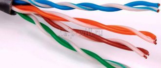
- Multimode fiber (MMF) has two core sizes: 50 µm and 62.5 µm. The wide core allows you to transmit multiple data streams simultaneously. Multimode fiber uses a light-emitting diode (LED) or vertical cavity surface emitting laser (VCSEL) as the light source. Due to its high dispersion and attenuation rates, it is typically used to transmit large amounts of data over relatively short distances.
- Single mode fiber (SMF) has a much smaller core diameter of 8.3 µm or 9 µm and a single light path that can travel longer distances. Single-mode fibers are typically used for longer runs, such as campus data networks, cable television transmissions, and telecommunications networks.
The way the cable is laid determines its design. The most common types of optical cables according to their application are:
- for indoor installation;
- for installation in cable ducts, with or without armor;
- for laying in the ground;
- suspended, with or without a cable;
The type of fiber determines the armor parameters, the presence of a suspension cable and other characteristics of the optical cable. Environmental conditions can be aggressive, be it soil or water. The most common line breakdowns are caused by mechanical damage. For example, during repair work, the cable may be damaged by large machines, or underwater networks may be cut off by submarines or ships. For each application scenario, the appropriate type of cable is selected.
Selecting the cable sheath type
Polyethylene sheath
The sheath of main optical cables can be made of low, medium and high density polyethylene (LDPE, PESP, HDPE, respectively). Let's take a closer look at each type.
Low-density polyethylene has a number of significant disadvantages: low strength and chemical resistance, “draining” of the shell at high temperatures. Pros: easy to cut during installation.
High-density polyethylene is very durable, has high mechanical and chemical resistance, but is inconvenient to cut and is prone to cracks.
Medium-density polyethylene has intermediate characteristics: increased resistance to adverse environmental influences, the necessary flexibility for installation at low temperatures, and resistance to ultraviolet radiation.
Moreover, the characteristics of such polyethylenes must correspond to a number of additional properties that make them suitable for use in optical cables, for example, have low shrinkage during extrusion. Unfortunately, there is no choice of domestic polyethylenes with the required characteristics on the market. Therefore, products from foreign suppliers are widely used, for example.
Flame retardant shells
If the cable needs to be laid in buildings and structures or at special facilities (electrical substations, enterprises, oil and chemical industries, etc.), a flame retardant sheath is required.
Sometimes the design provides for expanded requirements for the shell: non-propagation of combustion during group installation, low smoke and halogen-free. This makes it possible to use cables even in buildings with large numbers of people. According to GOST, such a sheath is indicated in the cable marking “ng(A)-HF” and the cables must have an appropriate fire safety certificate.
It is worth noting that it is not recommended to use cables with an outer sheath “ng(A)-HF” along the entire length of the FOCL-VL route as the main linear cable, since the polyethylene sheath is cheaper and has better performance characteristics in comparison with the halogen-free sheath.
Polymer compound shells (fire resistant)
In special cases, it is possible to use fire-resistant cables that remain operational even under fire conditions and are marked “ng(A)-FRHFLTx”. Such cables are used, for example, in fire alarm systems, as well as at particularly dangerous or critical facilities where it is necessary to ensure communication even in emergency situations (oil refineries, stadiums, etc.).
Tracking-resistant shells
When using self-supporting optical cables on lines of 35 kV and above, there may be a need to use a special tracking-resistant sheath. Indications for use are:
- if at the point of attachment of the optical cable the electric field potential is higher than 12 kV (but not more than 25 kV). For this purpose, special calculations of electric fields are made;
- the presence of polluting factors near power lines: sea coast, metallurgical production, coal mines, etc.
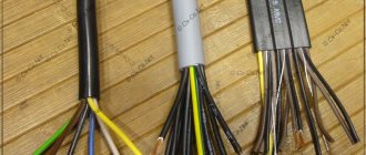
Installation
The process of connecting to the Internet via fiber optics is more complicated than it seems at first glance. All the advantages of the speed of light are contained in a fragile core that requires careful handling. Compared to copper twisted pair, servicing such communications requires increased qualifications of workers involved in installation work and connecting subscriber equipment. This is especially true for professional teams servicing the provider’s highways. Whether it's an emergency repair or a planned site connection, a network engineer always has a whole set of tools with him to maintain fiber optic cable for the Internet.
To connect several cable segments, they must be welded. This is possible with the help of expensive electric welding equipment, which includes a microscope.
Advanced models are equipped with CNC, which adjusts the welding angle and inclination to achieve the best result. The problem is that even a small error can have a negative impact on the speed of data transfer over the fiber.
Installation process:
- First you need to prepare the cable. Using a special tool, the outer and inner insulation is cut off, and the core is also cleaned.
- The stripped fiber must be treated with an alcohol-containing substance and then shortened to the desired length using a cutter.
It is important to note that it is very sharp and if it gets under the skin, it is unlikely to be removed without the help of a doctor, so installation should be done extremely carefully.
The welding area is then covered with heat shrink and heated to a high temperature.
- To connect the finished cable to the final equipment, it must be crimped. The fiber crimping process varies depending on the fiber type. If we talk about household use, then you can find ready-made patch cords on sale.
For home use, it is not necessary to purchase expensive equipment. You will still need a cleaning tool and a cutter, but they are inexpensive (around 1000 rubles), and you can do without a welding machine. It will be replaced by an inexpensive clip into which the prepared ends of the cable are inserted and secured. This is quite enough for the light flux to pass through the channel.
Comparison of optical fiber and twisted pair
A legitimate question arises: why, despite all the advantages of fiber optic cable, is the Internet delivered to most Russian apartments using copper twisted pair cable? The fact is that they are not directly comparable, they just serve different purposes.
Undoubtedly, optics have the advantage of the speed of light and are capable of delivering volumetric data over vast distances. This is its main purpose - to build entire highways. When it comes to the provider's shield inside the entrance, here the twisted pair is completely justified. Thanks to its ease of installation and sufficient speed for transmission over short distances (for example, inside an apartment building), it becomes indispensable.
The use of optical fiber is always justified on an industrial scale. When designing a local network for a small enterprise or office, the costs of cable and terminal equipment are taken into account. In this case, fiber optic cable for the Internet is inferior to copper due to the fact that its installation is many times more difficult and expensive.
Purpose
Fiber optic cable is one of the most modern and best ways in the world to quickly transmit data over long distances. At the same time, the development is not at all unique - it appeared at the end of the 20th century and has been effectively developing since then.
People actively communicate, improve their everyday life and economy, so the data transfer speed must be high. Currently, this cable is used by many Internet providers. It has no side effects, such as signal degradation over long distances and overheating. It is not affected by stray currents.