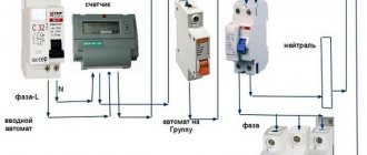
Installation and connection
Accepted colors of phase, neutral and ground wire
Before starting work, it is necessary to de-energize the room. Using a tester, it is checked whether voltage remains on the conductors. Using the probes of a screwdriver, you need to touch each core one by one. If the light does not light up, you can start working. It is prohibited to work with electricity turned on
It is also important to prepare tools in advance and provide the master with an autonomous light source
When connecting wires in a panel, it is important to remember that the colors of the wires indicate their purpose. The core can be completely painted in one color or another or have a color mark at the entrance to the device, that is, at the ends of the conductor
The following scale is used:
- Phase – gray, black.
- Zero is blue.
- Grounding – yellow-green.
The wire for installing the electrical panel must be laid in such a way that there are no sagging or unnecessary bends. To do this, the length of each segment is determined in advance with a small allowance of 2-3 cm.
All connections to the machine are made using jumpers. Single-wire rigid wire can be used for this purpose. If possible, it is better not to use jumpers, but to do everything through the connecting core. Thanks to it, the contact will be reliable and the appearance will be aesthetic.
About ease of installation and maintenance
To simplify the installation and subsequent maintenance of the electrical box in general and the metering device in particular, wiring with different colors should be used. It must be remembered that with single-color wires, it is generally accepted that the neutral wire is blue and the phase wire is brown. With two-color ones, red-white is phase, and blue-white is zero. The yellow-green wire is always ground. But these are the primary colors. In general, the color of the phase wire can be any color except blue and yellow-green.
Compliance with the colors of the cable cores is also necessary for service companies. After all, a professional electrician will also pay attention to this when working, and will be guided primarily visually. Therefore, you should not neglect this rule.
Connecting a three-phase meter
Having understood the connection of a single-phase meter, you can move on to a three-phase one. Despite the fact that they have twice as many contact terminals, the essence of how to properly connect an electric meter to a 380-volt network does not change. The only difference in the circuit for such electricity metering devices is the presence of three pairs of phase connections. The last two contacts also go to the input and output of the neutral wire.
The only thing that can be a little more difficult in connecting three-phase electricity meters is if the meter is a secondary switching device. In this case, power to the electric meter is supplied from transformers that are installed on the input power busbars. Otherwise, the installation of such metering devices does not differ from the connection of direct connection devices, which are currently the most common.
It is important that when carrying out electrical installation of the wiring of an electrical cabinet or box, it is always possible to turn off the input voltage, since regardless of the rating, whether it is 220 volts or 380, it is life-threatening, and therefore any work in this direction must be carried out with the power turned off.
Machines, wires, security
If you are wiring electricity in an apartment from a panel yourself, then there must be automatic circuit breakers, that is, automatic power cut-offs for a certain group of points in the home network. So, for a socket, the circuit breaker must be no less than 16 A, the cross-section of the wire connected to it is 2.5 mm². A 10 A automatic circuit breaker should be responsible for lighting; the wire connected to it and to the lighting fixtures should be 1.5 mm².
We use machines for each group of consumers
One of the most “powerful” appliances in the apartment is the electric stove and boiler; wires with a cross-section of 4 mm² must be connected to them, and their circuit breaker must be at least 20 A. All this is placed in a distribution panel, which is placed in the corridor
Important: do not use the machine more than indicated in the list below, otherwise the wire will simply burn out
Cable cross-section – 1.5 mm², automatic 10 A, 2.5 – 16 A, 4 – 20 A.
To connect all the necessary points to the machine, you need to use a special bus and in no case pieces of wires.
Bus for connecting all points to the machine
Each panel must include an input machine (a toggle switch that de-energizes the entire apartment). This is an important point, since it is used mainly in emergency situations, for example, in case of a fire or a water pipe leak from the upper apartment.
For an apartment or any other residential premises, insulated copper wires are used.
We use only copper wires
They do not break, since aluminum ones do not withstand bending, and they also have the ability to conduct current better.
Safety regulations:
- Before installing the wiring, you must turn off the electricity.
- Do not lay the cable when it is live.
- If it is necessary to solder wires, then this must be done in special gloves.
- Before tightening the wires into the tube, you need to remove all burrs from them.
Pulling contacts
Surely, if a person installed electrical wiring in an apartment on his own, he already knows that the connection contacts must be tight enough to prevent heating and failure of the wires. But it won’t hurt to remind you of this. Moreover, this rule applies primarily to the electric meter and power cabinet circuit breakers.
The contact terminals of the electricity meter have two mounting screws. First, the wire is fixed in the socket with the upper screw, then the lower one is pulled through. It is important to remember that after the power cabinet has been operating under load for one to two weeks, it is necessary to re-check the tightness of the fixing screws of the electric meter and machines. Particular attention should be paid to the zero bus and its contacts, since if the tightening is insufficient, it is the “zero” that begins to “burn.”
Criteria for choosing wisely
The key to uninterrupted operation of the home electrical system is the quality of components. Therefore, at the stage of purchasing them, one of the key tasks is to choose a cable of appropriate quality.
To help you choose the right cable, you need to carefully study the product labeling. The cable must indicate: brand, manufacturer's name and compliance with GOST or technical specifications. The cross-sectional size and grade of the cable must be repeated at equal intervals along the entire length of the outer braid of the product.
The marking of any electrical cable is represented by numbers and three letters.
The first digit of the numerical designation determines the number of cores, the second digit – the cross-sectional area of each of them, the third – the calculated network voltage. The remaining numbers indicate the flexibility class of the cord. The first letter determines the type of material used to create the top braid of the insulation.
If you have a product in front of you that has the letter “A” in the first place in its marking, this means that the cores are made of silver metal – aluminum; if such a letter is missing, the threads are made of copper
The second letter indicates the wire type:
- “K” – control;
- “P” – flat;
- “M” – installation;
- “Ш” or “У” – installation;
- “Mg” – mounting with flexible core.
The third letter of the marking determines the material used for internal insulation of the cores.
Options for its designation and decoding:
- “P” – insulation is made of polyethylene;
- “B” or “BP” – the braid is made of rubber;
- “Pv” – vulcanizing polyethylene is used;
- “Ps” – self-extinguishing polyethylene was used;
- “C” – the outer braid is made of lead;
Rubber insulation can be protected by a Nairite “N” sheath or a polyvinyl chloride “B” sheath.
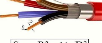
An example of decoding the designation: VVG 4x2.5-380 - a cable with four copper cores with a cross-sectional area of 2.5 mm, designed for a voltage of 380 V, insulated with PVC braiding and enclosed in an outer PVC sheath
The following letter indicates the type of cable: “NG” - non-flammable and fire-resistant, “B” - armored, “LS” - does not emit smoke when melted. Products with an armored shell are used where there is a possibility of mechanical damage.
The presence of the letter “E” in the marking indicates that there is filler between the cores. The letter combination “OZH” indicates that this is a single-wire conductor.
Purpose of the electrical panel
Externally, products in which protective and accounting equipment are installed look different. This can be a compact plastic box with tinted glass installed in the hallway, or a large metal panel mounted into the wall on the landing.
We are talking about an electrical panel, which is necessarily present in residential buildings, office buildings, in production - wherever power lines are laid.
Electrical panels, depending on the installation location and purpose, can be distribution, group, accounting and distribution. For example, a box with a counter is called an accounting and distribution box, and a box in the hallway in which only machines are located is called a group box
Possible installation locations are specified in the regulatory documentation, but largely depend on the purpose of the shield. For example, for private houses, one of the electrical panels, with an electric meter and an input device, is usually installed on the street, on a pole or facade.
Shield functions:
- receiving electricity from the central main line - a power line connected to the house;
- energy distribution among consumer groups or individual lines;
- protection of the electrical network from high loads and short circuits;
- accounting for quality and stabilization of electricity;
- protection of power grid users from electric shock.
Simply put, the uninterrupted transmission of electricity to the house, the safety of all residents, and the safety of property will depend on the correct assembly of the electrical panel.
Connecting a meter: rules and basic requirements
Exactly all the requirements are specified in the PUE, and the basic rules are as follows:
- Must be installed with protection from weather conditions. Traditionally they are mounted in special boxes (boxes) made of non-flammable plastic. For outdoor installation, the boxes must be sealed and must provide the ability to control readings (have glass opposite the display).
- Fixed at a height of 0.8-1.7 m.
- The meter is connected using copper wires with a cross-section corresponding to the maximum current load (available in the technical specifications). The minimum cross-section for connecting an apartment electric meter is 2.5 mm 2 (for a single-phase network this is a current of 25 A, which is very low today).
- The conductors are insulated, without twists or branches.
- With a single-phase network, the state verification date of the meter is no older than 2 years, with a three-phase network - one year.
Read also: Stainless steel cutters
The installation location of the meter in apartment buildings is regulated by the project. The meter can be installed on the landing or in the apartment - in the panel. If placed in an apartment, it is usually not far from the door.
Input panel complete set
There are also several options in a private house. If the pole is in the yard, you can place the meter on the pole, but it’s better to place it indoors. If, according to the requirements of the energy supply organization, it must be located on the street, they place it on the front side of the house in a sealed box. The machines going to groups of consumers (various devices) are mounted in another box in the room. Also, one of the requirements when installing electrical wiring in a private house: the wires must be visually inspected.
Installing a meter on a pole
In order to be able to carry out work on the electric meter, an input switch or machine is installed in front of it. It is also sealed, but there is no way to put a seal on the device itself, like on a meter. It is necessary to provide for the possibility of separate sealing of this device - buy a small box and mount it inside the apartment panel or place it separately on the landing. When connecting a meter in a private house, the options are the same: in the same box with the meter on the street (the entire box is sealed), in a separate box next to it.
Reasons for replacing cables
Complete or partial replacement of electrical networks usually needs to be performed in two cases:
- Wiring age. Major renovations are recommended to be carried out 15-20 years after moving into a new apartment. During this time, the installed communications wear out, becoming a source of potential danger for residents.
- Redevelopment and renovation of premises (especially with the addition of powerful household appliances). Modern electric stoves, washing machines, and dishwashers place increased demands on wiring. It is not advisable to connect them to old electrical networks due to the mismatch of characteristics. When planning to purchase such units, it is better to update communications in individual rooms, for example, in the kitchen or bathroom.
Regardless of the reason for replacing electrical networks, work should begin with drawing up an electrical wiring diagram and selecting cable products.
Electrical Panel Components
The assembly of an electrical panel requires the presence of mandatory components, which include circuit breakers, residual current devices (RCDs), electricity meters, buses, as well as additional and auxiliary components that add convenience to the operation of the panel: voltage control relays, light indicators, digital voltmeters, contactors and etc.
Among the most respected by specialists are the manufacturers of components used in the installation of electrical panels - ABB, Legrand, Shcneider Electric. The prices for devices of these brands are approximately the same. Chinese devices are much cheaper, but practicing electricians claim that once you use Chinese equipment to complete an order, you can lose your reputation for a long time, so they use such components only at the request of a customer who cannot afford branded components.
Installation
Having secured the power cabinet at the required level, you need to insert wiring from the apartment or room into it (the wires must enter from above). This is usually done either covertly or openly. In the second case, it is necessary to use corrugated plastic or metal armor.
Distribution machines are connected to each other from above with small pieces of wire. From the input circuit breaker (usually a two-pole device), one phase wire is connected to the 1st contact of the electric meter, and a jumper connects the second terminal to the distribution machine (how to connect the machine, as well as how to connect the meter, can be seen from the attached diagrams). Considering that all distribution circuit breakers are interconnected, the power to them will be the same. Wires that go inside the apartment or room are connected to them from below.
The circuit diagram for connecting a single-phase meter in a private house or apartment is not complicated, if, of course, it is fully understood.
The neutral wire from the input circuit breaker goes either directly to the second contact of the electric meter, or to it, but through a residual current device (RCD). It must be remembered that if, when connecting an RCD, the zero is connected to ground, then the residual current device will “knock out” and it will not work normally.
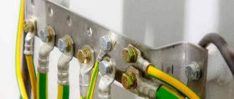
The jumper from the third contact of the electricity meter is connected to the zero bus, to which all neutral wires coming from the apartment or room are connected.
Here, in fact, is the entire connection of an electricity meter in general terms. After this, all that remains is to apply the phase to the input machine. In general, connecting an electric meter, the circuit of which is known, will not be difficult.
There is a small nuance in such work - the wires from the input machine to the single-phase or three-phase meter and from the meter to the distribution circuit breakers must have a larger cross-section than those coming from the apartment or room, and no less than the incoming power cable.
Read also: Autonomous diesel oven
Preparation of jumpers and connection diagram
Making a jumper in a non-breaking way
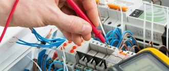
The conductors need to be prepared for connection in the panel. To do this, you need to strip the ends from the insulation using a knife or a special tool. The cores should be inserted into contact and tightened well with a screwdriver.
During operation, you need to pay attention to the following:
- The insulation should not get caught in the clamp.
- The exposed part of the wire should not stick out from the contact over a large area. This requirement is made by network organizations that seal meters. This helps prevent illegal connections from outsiders.
- The upper screw is tightened first, followed by the lower one.
The last step is to check the reliability of the fixation. The veins need to be carefully touched and pulled apart. The conductor should not swing or stagger.
Connection of machines
Next you need to connect the neutral wire. It is connected using a jumper from the lower right contact of the automatic two-pole switch to the third contact of the electric meter. The ends also need to be stripped of insulation, connected and tightened with screws. The wires must not touch each other. Be sure to leave a gap between them.
Now you need to connect the outgoing wires from the meter. First, the phase is connected through a jumper to the upper contact of the machine. The ends are stripped and joined. The phase also needs to be distributed among other sources in the directions of the machines.
There should be one contact left from the electricity meter in the apartment. This is the outgoing zero contact, which must connect to the zero bus. Usually it comes complete with a plastic box. Length, dimensions and configuration vary by manufacturer.
Types of meters
Before connecting a single-phase meter, you should select a suitable electricity meter. The same applies to a three-phase electric meter. The apartments use a single-phase electricity meter, which operates with a voltage of 220 volts. If you look at the contact terminals of such devices, you can see that the connection circuit of a single-phase meter contains 4 of them - these are the input and output of the phase wire, and the input-output of the zero wire.
In a three-phase meter there are 8 such outputs - 3 pairs per “phase” and a pair for zero. The fact is that three-phase meters are used for a voltage of 380 volts and are connected if there is a need to power machine tools and similar equipment. Sometimes (much less often), to connect powerful electric stoves. There is no two-phase connection system.
Each of these types of metering devices can also be divided into single-tariff and two-tariff, in which only the circuit of the meter itself differs, but not the order of inclusion. The fact is that, according to current legislation, the cost of electricity spent in the period from 11 pm to 8 am is significantly lower than the “daytime” price, and therefore for those who spend the bulk of electricity at night, a two-tariff meter will be an excellent solution to save on utilities. A single-tariff meter does not have a time switching function, and therefore the cost of electricity does not change around the clock.
The connection diagram for a single-phase meter is no different for single-tariff and two-tariff devices, as is the connection diagram for three-phase meters; they are mounted in exactly the same way.
Also, these devices can be electronic and analog.
What does an electrical panel consist of?
The input cable is connected to the electrical panel through holes in the housing, then connections are made to the electrical equipment in accordance with the diagram. For example, when assembling a switchboard, the power cable is connected to the input circuit breaker, and the corresponding equipment that belongs to each consumer group is connected to it.
Inside a modern home electrical panel there is a large number of different switching and protective devices and other types of equipment, including:
The electrical panel body must be grounded, as well as its metal doors and other live parts. To restrict access by unauthorized persons and prevent electric shock, it must be locked with a key.
What does an electrical panel consist of?
The input cable is connected to the electrical panel through holes in the housing, then connections are made to the electrical equipment in accordance with the diagram. For example, when assembling a switchboard, the power cable is connected to the input circuit breaker, and the corresponding equipment that belongs to each consumer group is connected to it.
Inside a modern home electrical panel there is a large number of different switching and protective devices and other types of equipment, including:
- metering device (electricity meter).
- automatic switches (input or disconnecting groups and individual consumers);
- RCDs and automatic devices;
- timers;
- voltage relay;
- phase control relay;
- other automation.
The electrical panel body must be grounded, as well as its metal doors and other live parts. To restrict access by unauthorized persons and prevent electric shock, it must be locked with a key.
Methods for installing wiring in an apartment
It is important to immediately make a reservation that the following options will only be relevant for buildings with walls made of concrete or brick. They are not suitable for wooden houses, so the methods are not universal
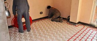
The first method will be relevant for those houses where there is not even a layer of plaster on the walls. Then the wiring can be placed directly on the surface of the walls. There are also two methods here, which were already mentioned earlier:
- Place the cables in corrugated plastic pipes if the thickness of the finish allows.
- Simply lay the cables open if they have double or triple insulation.
The second method is encountered most often, because it is suitable for cases when:
- The plaster has already been applied.
- Its layer will not cover the wires and you will have to make grooves directly in the wall.
This is a more difficult and longer path, but most often it turns out to be the only suitable one. In addition to the fact that the grooves have to be made, the wires in them will also need to be carefully fixed - with plaster patches or plastic staples.
*(Dowel staples are especially suitable for ceiling wiring)
To make all the grooves correctly, it is better to make markings according to the diagram directly on the wall, then there will definitely not be any difficulties and there will be a chance to check everything again and correct something.
Now you need to determine how to lay the cables themselves. The lines from the distribution board to each junction box can be laid using the methods described in this table.
| Highway location | Peculiarities |
| Along the upper edge of the wall in a groove or corrugated pipe | Most often used |
| Over the floors until the floor screeds are poured (in plastic pipes) | This is the shortest way. Here, by the way, grooves are not useful either, since when the floor is filled, all the wires will be hidden. For such wiring, sockets built into baseboards are usually needed. By the way, now you can purchase special kits - a special plinth with cable channels, sockets, switches, junction boxes, etc. True, it is not suitable for any finish. |
| Along the ceiling | Here, most likely, you will have to make grooves, however, the consumption of materials will also be economical. Junction boxes can also be placed on the ceiling, but this will hardly be convenient when repairs are required. This method is only relevant when a suspended or suspended ceiling is intended to hide the lines. |
When installing the wiring yourself, only the first option is suitable, and despite the great advantages of the other two, it is no worse than them. It will just require more time, but since the plan to install the wiring with your own hands has reached the strobing stage, the hardest part is already over.
*(Grooves are the penultimate stage on the route of wiring)
Calculation of cable cross-section
The cross-sectional areas of the wire are specified in the relevant standard. Their value depends on the current strength, the material of the TPG and installation conditions. It is worth remembering that when operating the cable, using its maximum capabilities, the conductors will heat up to high temperatures.
If several such wires are used in one tray, then when heated together, the permissible current value will decrease to 30%.
In order to correctly calculate the cable cross-section for home lines, it is necessary to calculate the total sum of the current values of all devices located in the apartment.
The formula for calculation is P/V, where
- P – power of devices, which is indicated in technical documents;
- V – network voltage of 220 V.
The cross-sectional area is calculated in millimeters. For example, one square millimeter of aluminum wire can carry 4-6 Amperes. For a copper cable this figure is within 10 Amperes.
Sample calculation. There is a device with a power of 4 kW. Using the above formula, the current can be found. 4000 W/220V = 18.18 A. In order to provide power to this device, it is necessary to lay cables with copper threads with a cross-section of 1.8 mm2.
It is best to use the value above and multiply the resulting number by 1.5. It turns out that the most favorable option for powering this device is a copper cable with a cross-section of 2 mm2. If an aluminum cable is used rather than copper, the thickness of the wire should be 2.5 times greater.
There are special tables on the Internet that can be used to select the cable cross-section without using formulas. Using tables greatly simplifies the task of calculating the required cable cross-section. It is enough just to know the current values of all electrical appliances. When designing hidden wiring, the table values must be multiplied by a factor of 0.8.
If the installation method is open, then it is better to use a wire with a cross-section of 4 mm2 or more, it will be more reliable. It is also preferable to choose products with high mechanical strength.
According to the characteristics of the cross-section, the cable for entry into the house must be one step higher than the cross-section of the cable for servicing already installed electrical appliances.
In order to save money, such a cable can only be used to enter the house and connect it to the terminal block, and then through the machines, draw lines of the required cross-section.
According to the Electrical Installation Rules 7.1.34, each line is calculated separately, focusing on a specific load. But there are options that are used for all residential buildings and have standard cross-sectional dimensions.
- Cable VVGngLS 3x1.5 mm2 is used for installation of electrical wiring for the construction of lighting lines. To protect the lines, the machine is set to 10A;
- Wire VVGngLS 3x2.5 mm2 is suitable for installing plug sockets, the machine is installed at 16A;
- The VVGngLS 3x6 mm2 cable is needed for connecting high-power household appliances. The auto switch is set to 32A;
- Wire VVGngLS 3x6 mm2 is most often used for entry into an apartment or private house. Before entering it is better to calculate the actual load. And since the power of consumers increases, it is advisable to take a VVGngLS 3x10 mm2 cable.
Some tips and safety measures
To summarize all of the above, it makes sense to summarize the basic safety measures when installing power cabinets and connecting electric meters:
- All work is carried out with the voltage removed;
- The wiring should start from the apartment or room, and the power input should be connected last;
If you clearly understand how to connect a single-phase or three-phase electric meter, no special difficulties will arise during its installation, and therefore it is quite possible to connect the electric meter yourself. And if all of the above measures are observed, the electrical wiring will continue to bring light into the apartment for a long time, and its maintenance will not cause any problems.
Commissioning or reconstruction of electrical wiring in a house or apartment is rarely complete without installing or replacing an electric meter. According to the standards, work can only be performed by specially trained people who have permission to work in networks with voltages up to 1000 V. But you can install all the elements and connect the meter to the load (electrical appliances) without connecting the power supply yourself. Afterwards, you need to call a representative of the energy supply organization to test, seal and start up the system.
One of the housing options for the meter
Plan
Before you do the wiring in the apartment with your own hands from the panel, you need to create a plan for it. And this moment must be approached very seriously, because the safety of all residents of the apartment will depend on the correctness of planning, and subsequently implementation in kind. If there is at least a minimal understanding of what electric current is, then there will be no problems. You need to calculate the load and make a drawing on paper. To correctly identify all electrical points in the apartment (sockets, switches, wires, inputs and outputs), it is necessary to adhere to the standardized markings on the plan. This diagram will help to correctly lay cables that will withstand a particular load.
On the same plan, it is important to take into account the location of household appliances: for example, an electric kettle and a boiler require wires with a large cross-section, but a light bulb and a TV do not need them
An example of an electrical diagram for an apartment
The wiring points must be indicated on the diagram. There are three types of wiring - parallel, serial and mixed. It is the last option that is most rational to use - it is cheaper than all others in terms of material costs, and it is also the most effective. To make it easier, here is a rough plan for the breakdown of connection points:
- Light in the kitchen, hallway, living rooms.
- Light in the toilet and bathroom.
- Power supply for outlets in living rooms and hallways.
- Power supply outlets in the kitchen.
- Power supply for sockets for the electric stove, if there is one. Also, if there is a boiler, it is also better to allocate it to be connected via a separate wire directly to the panel.
Distribution of machines by functional groups of electrical appliances
The above plan is just an example, there can be a lot of options, the main thing is to calculate the loads and correctly group the connection points.
Calculation of loads on electrical wiring
The preparatory work does not end with the creation of a plan: it must be approved by the relevant regulatory authorities, and only after that begin work on installation and cabling.
Connection diagram for a single-phase electric meter
Meters for a 220 V network can be mechanical or electronic. They are also divided into single-tariff and two-tariff. Let us say right away that connecting any type of meter, including two-tariff ones, is carried out according to the same scheme. The whole difference is in the “filling”, which is not available to the consumer.
If you get to the terminal plate of any single-phase meter, you will see four contacts. The connection diagram is indicated on the back of the terminal block cover, and in a graphical representation everything looks like in the photo below.
How to connect a single-phase meter
If you decipher the diagram, you get the following connection order:
- Phase wires are connected to terminals 1 and 2. The phase of the input cable comes to the 1st terminal, the phase to the consumers goes from the second. During installation, the load phase is connected first, and after it is secured, the input phase is connected.
- The neutral wire is connected to terminals 3 and 4 using the same principle. To the 3rd contact there is a neutral from the input, to the fourth - from consumers (machines). The order of connecting the contacts is similar - first 4, then 3.
The meter is connected with wires stripped to 1.7-2 cm. The specific figure is indicated in the accompanying document. If the wire is stranded, lugs are installed at its ends, which are selected according to thickness and rated current. They are crimped with pliers (can be clamped with pliers).
When connecting, the bare conductor is inserted all the way into the socket, which is located under the contact pad. In this case, it is necessary to ensure that no insulation gets under the clamp, and also that the cleaned wire does not stick out from the housing. That is, the length of the stripped conductor must be maintained exactly.
The wire is fixed in old models with one screw, in new ones - with two. If there are two mounting screws, tighten the one on the far side first. Tug the wire slightly to make sure it is secure, then tighten the second screw. After 10-15 minutes the contact is tightened: copper is a soft metal and is pressed down a little.
Read how to do the wiring in your home yourself here. The features of electrical wiring in a wooden house are written here.
This applies to connecting wires to a single-phase meter. Now about the connection diagram. As already mentioned, an input machine is placed in front of the electric meter. Its rating is equal to the maximum load current; it is triggered when it is exceeded, excluding equipment damage. Afterwards they install an RCD, which is triggered when the insulation breaks down or if someone touches live wires. The diagram is shown in the photo below.
Connection diagram for a single-phase electricity meter
The circuit is not difficult to understand: from the input, zero and phase go to the input of the circuit breaker. From its output they go to the meter, and from the corresponding output terminals (2 and 4) they go to the RCD, from the output of which the phase is supplied to the load breakers, and the zero (neutral) goes to the zero bus.
Please note that the input circuit breaker and the input RCD are two-contact (two wires enter) so that both circuits open - phase and zero (neutral). If you look at the diagram, you will see that the load breakers are single-pole (only one wire goes to them), and the neutral is supplied directly from the bus.
Watch the meter connection in video format. The model is mechanical, but the process of connecting the wires is no different.
General principles for wiring in the panel
The switchboard contains all the equipment and mechanisms for connecting consumers to electricity
For its proper operation and safety, it is important to use suitable wires and high-quality parts, because due to a malfunction, users may be left without light, or a fire may even start. The function of conductors in an electrical panel is to connect controllers, indicators and other devices
The entire panel, including the metal casing, must be reliably grounded. Ideally, you should also put a lock on it so that unauthorized people do not have access to the equipment.
The connection must be made in such a way that the connecting wires do not sag. To do this, you need to carefully measure the distance between the connection elements and cut off a few centimeters more so that they can be inserted into the terminals. You cannot save on this, and if the calculations turn out to be incorrect, it is better to repeat the operation.
Currently, I have chosen electrical panels and devices from ABB.
But knowledge of modular and panel products from Schneider Electric, Legrand, Hager allows me to assemble electrical panels from components from any manufacturer. Therefore, when choosing a company, I always go to meet the customer of the shield.
But it should be noted that the prices from these manufacturers are almost the same. The only difference is different series of devices, but even if they are similar in parameters, they are also the same.
Below I will give a comparative calculation of the cost of an electrical panel of different series of ABB and Schneider Electric for one of the orders (the calculation is already outdated, but is still relevant).
Comparison of prices for automatic machines, RCDs, switches from ABB and Schneider Electric.
Electrical panels, at the request of the customer, can be equipped with various additional “wants” and protections: light indicators, digital voltmeters, contactors with on/off switching of all or part of the load, timers (time relays) for turning on the load according to a schedule, voltage control relays, etc.
What elements does an electrical panel consist of?
It is necessary to purchase the components of the electrical panel immediately, so as not to subsequently waste time and not travel to the electrical store several times a day. The power of the shield is determined, it is 15 kW, which means that the maximum power consumption will not exceed 15 kW/h.
Electrical panel of a private house, list of elements:
- Electric energy meter. The meter is the first element that must be installed in the panel. The best solution would be to purchase an electronic device designed to connect three phases. Such measuring instruments have high accuracy and a long service life. All information is displayed on a digital screen. Electronic meters can be programmed to operate in several tariffs.
- Electrical shield. Now in stores there are a large number of electrical panels of various sizes and designed for a certain number of elements. The price of the product varies depending on the presence of a DIN rail, a built-in lock, as well as an inspection window (especially for taking readings from the meter). You should pay attention to protection from dust and moisture, its level should be at least IP 54. Dimensions - 445 × 400 × 150, and a wall thickness of 1 mm.
- Input circuit breaker. You should purchase a three-pole machine, because the voltage supplied to the house will be 380 V, which means the presence of three phases.
- Residual current device (RCD). It is required to be installed, since it is a protective element when a dangerous potential appears on the body of an electrical device.
- Circuit breakers. The amperage should be selected based on the consumer load, which will be discussed below.
- Voltage relay. Protects household electrical appliances from power surges. Many users install a relay, but it is not a required element. Also now widely used is the surge protection device (SPD). For example, when lightning strikes an overhead power line, the voltage in the house will reach high limits, which will be destructive for all equipment. The SPD will turn off the network in time, but, like the voltage relay, it is not installed often.
- Measuring instruments. They are also an optional element of the electrical panel. Measuring instruments include ammeters and voltmeters, often combined into one product.
Common mistakes when connecting the machine to the network
Unfortunately, even experienced electricians with many years of experience behind them make minor mistakes at first glance, which can later lead to very big problems. To avoid such errors when connecting the input machine, you need to familiarize yourself with them in advance. Prevent a problem before it occurs.
Wire clamp with insulation
A very popular mistake that is made mainly due to inattention. The main difficulty is that a visual inspection may not show any results: all the machines in the electrical panel are intact, the wires are not damaged, and there is still no light in the apartment.
And the problem is the incorrect connection of the power cable, or rather, too small a section of the removed insulation. The technician removes a small piece of insulation from the wire, places it in a fixed contact and tightens the bolt. The standard connection of the machines is in the panel and everything is done according to the rules. But only the contact could get not to the conductive core itself, but to the insulation. Result: poor contact, which will lead either to a burnt-out machine or to a lack of light in the apartment. It may take a long time to determine the problem and reconnect the cable to the packager.
Therefore, in order to avoid such consequences, the connection of a single-pole or two-pole machine must be made with a high-quality stripped wire. And it’s okay if the cleaned core peeks out a little from the insertion point.
Connecting several wires of different sections to the machine
Before installing circuit breakers, you need to know how to do it correctly. And often in apartment panels you can see several wires that are installed in one regular place for connection. And it’s good if it’s 2 wires, but many craftsmen try to connect 3 or more wires of different sections to the machine. After which the life of the circuit breaker is reduced several times.
If the wires to the machine have different cross-sections, then when the contact is tightened, the one with the larger cross-section will be well secured. A cable with a smaller diameter will “walk” freely in the package’s seat. The result will be poor contact, which will soon lead to complete burnout of the connection point of the machine.
Therefore, it is best to connect the machines to each other with a single piece of wire, stripped only in places of direct contact with the circuit breaker. This piece of wire is also called a comb bus, which you can make yourself.
Connecting several machines to a meter or to each other can also be done using special crimp terminals NSHVI-2. These are consumable products into which 2 wires can be pulled at once. The only downside to this installation option is the need to purchase special crimping pliers.
Incorrect formation of core ends
How to connect circuit breakers in a panel is already known and the main errors have been discussed, but even such a minor error as incorrect formation of the end of the conductor can lead to the need to replace the switch.
The sequence of connecting cables to machines is standard: strip the core to the required length, guide the wire into the seat and tighten the lock, which is most often made for a Phillips screwdriver. They try to make the end of the conductor straight. But in order to improve contact at the junction of the wire and the copper plate of the machine, a U-shaped bend must be made at the end of the cable.
This is the most reliable advice on the question of how to properly connect machines to the input power supply or apartment wiring. The U-shaped bend allows you to increase the area of contact between the wire and the copper plate of the bag, and, accordingly, improve the quality of contact. The rest of the work will be done by the ribbed surface of the slots for connecting the machines.
Design, principle of operation and types of introductory machines
Electrical line switching devices that provide protection against overloads and short-circuit currents are called circuit breakers. It is designed to ensure the safety of the power line in the event of an emergency.
This definition applies to all switching devices that are mounted in the electrical panel. The main difference between an input circuit breaker and a linear circuit breaker is that it has a higher rated current.
And it is calculated depending on the permitted power consumption of electricity. The input circuit breaker (IA) is the second stage of protection, used as a switching device. In the event of an overload or short circuit, the linear element must operate first.
VA has two degrees of protection:
- Overload protection. It is a bimetallic plate. When the permissible current is exceeded, it heats up. As a result, it bends and activates the thermal release mechanism. The greater the load, the more current flows through the plate. The heating rate increases. And the machine works faster. After disconnecting, you will not be able to turn on the device immediately. It takes time for the bimetallic plate to cool and return to its original position. Only after this can you put the device into operation.
- Short circuit protection. The machine has a current coil (solenoid). When there is a short circuit in the line, an instantaneous increase in current occurs. The solenoid retracts the core, the current protection is activated and turns off the power. The response time is a fraction of a second.
The VA is mounted before or after the electricity meter on a DIN rail. Depending on the supply voltage, they can be single-pole, two-pole, three-pole or four-pole. Bipolar ones are installed when connecting a single-phase voltage of 220 V.
Installed in apartments of multi-storey buildings. To provide electricity to cottages or private houses, three-phase voltage is supplied. To connect them, four-pole VAs are used. Previously, three-phase voltage was not connected; old houses were supplied with single-phase voltage.
The PUE prohibits the installation of single-pole circuit breakers as input switching systems. Due to the variation in response times, they cannot provide the necessary protection, which will lead to equipment damage or fire.
VA are characterized by:
- Rated current. A nominal value is applied to the device body at which the device can operate for a long time without shutting down, for example, C40. This means that the VA can handle up to 40 amps of current indefinitely. However, these readings are determined for an air temperature of 300C. At a lower temperature, the VA can withstand currents higher than the rated one. And at an increased temperature, the thermal protection operates at lower loads. This should be taken into account when choosing the location where the input panel will be installed;
- Number of poles. For single-phase voltage, two-pole devices are used, and for three-phase, four-pole devices. Some specialists install three-pole ones, which does not provide reliable protection;
- An important indicator is the time it takes for the machine to operate. When overloaded, this time can vary from several tens of minutes to several seconds. This depends on the amount of current flowing through the bimetallic strip. Short circuit protection is activated in a fraction of a second.
All installed devices must be consistent in current. For example, if the meter indicates a current of 40 A, then the VA must be rated for a current of less than 40 amperes. And linear devices in total should not exceed the current VA.
If the load is small, then a meter is installed, and then an automatic machine. When calculating, pay attention to the starting load currents.
The machines are divided into three subgroups B, C, D:
- B - these are the most “delicate” devices. Allows loads with inrush currents not exceeding 3-5 rated values indicated on VA;
- C - common machines installed in private houses and apartments. The excess inrush current varies from 5 to 10 times the nominal value;
- D – used in networks with high inrush currents and short-term overloads. The excess is 10-20 times the nominal value.