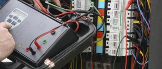
The danger of electric shock to people, damage to electrical equipment, additional load on the network and a short circuit with the possibility of fire are far from uncommon even with externally working electrical wiring. The reason for this is the thinning and loss of electrical insulating qualities of the conductor sheath. Let's look at what safety measures need to be taken in this case, what insulation resistance measurements are, how often they are carried out, why current leakage occurs and what its consequences may be, for what reasons the insulation deteriorates, what methods and instruments are used and what the instructions for taking measurements look like .
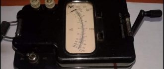
Timely checking of insulation resistance allows you to avoid an accident in the electrical network Source remkip.ru
Verification: test or measurement?
As a first step, it is useful to clarify the difference between two types of testing that are often confused - dielectric strength testing and insulation resistance testing.
The dielectric strength test, also called the flashover test, determines the ability of an insulation to withstand a medium-duration voltage surge without sparking. In fact, such a voltage surge can be caused by lightning or induction as a result of a faulty power line. The main purpose of this test is to ensure compliance with building codes regarding creepage distances and clearances. This test is often performed using AC voltage, but the test also uses DC voltage. This type of measurement requires the use of high voltage cable testing facilities. The result is a voltage value, usually expressed in kilovolts (kV). Electrical strength testing can be devastating if it fails, depending on the testing levels and the energy capabilities of the instrument. Therefore, this method is used for routine testing on new or refurbished equipment.
Under normal test conditions, insulation resistance measurement is a non-destructive test. This measurement is performed using a lower DC voltage than the dielectric strength test and gives a result expressed in kOhms, MOhms, GOhms or TOhms. The resistance value indicates the quality of the insulation between two conductors. Since this test is non-destructive, it is particularly suitable for monitoring the aging of the insulation of operating electrical equipment or installations. An insulation tester, also called a megger, is used for this measurement (meggers are available with a range of up to 999 GΩ).
Taking measurements
The reliability of insulation is determined in several steps:
- A LABSIZ electrician inspects the electrical circuit. Visible violations of the insulating layer, open sections of wires are immediately recorded in the protocol. All elements are examined: cables, contacts, grounding.
- The circuit being tested is de-energized. During testing, devices are turned off and lamps are unscrewed from their sockets. The power switches are turned to the "Off" position. This is necessary so that sensitive equipment does not burn out when strong currents are applied to the line.
- The absence of voltage in the circuit is checked. LABSIZ specialists use sensitive voltmeters that exclude the presence of extraneous current.
- Voltage is applied to the line. The insulation resistance of switches, lamps, and sockets is measured. Studies of the parameters of the insulating layer are carried out between all phases and phase by phase. Separately, resistance measurements are made between phase and ground. The frequency of data recording is once every 60 seconds.
- The circuit is freed from capacitive charge. For this purpose, a compact grounding conductor is used. Do not connect household appliances until the voltage has been removed.
A qualified electrician must carry out the investigation and write the technical report. The document prepared by a LABSIZ specialist meets the requirements of the law and can be presented during official inspections.
Typical causes of insulation failure
Since measuring insulation resistance with a megger is part of a broader preventative maintenance policy, it is important to understand the reasons why insulation performance may deteriorate. Only this will allow you to take the right steps to eliminate them.
The causes of insulation failure can be divided into five groups. However, it must be borne in mind that in the absence of any corrective measures, various causes will overlap each other, leading to insulation breakdown and equipment damage.
Electrical loads
Basically, electrical loads are associated with the deviation of the operating voltage from the nominal value, and both overvoltage and undervoltage have an impact on the insulation.
Mechanical loads
Frequent sequential starts and stops of equipment can cause mechanical stress. This also includes problems with balancing rotating machines and any direct stress on cables and installations in general.
Chemical influences
The presence of chemicals, oils, aggressive fumes and dust generally negatively affects the performance of insulating materials.
Stresses associated with temperature fluctuations:
In combination with the mechanical stresses caused by successive starts and stops of equipment, the properties of insulating materials are also affected by the stresses generated by expansion and contraction. Working at extreme temperatures also causes aging of materials.
Environmental pollution
Mold and foreign particles in warm, humid environments also contribute to the deterioration of the insulation properties of plants and equipment.
The table below shows the relative frequency of various causes of motor failure.
External pollution:
In addition to sudden insulation failures due to extreme events such as floods, factors that reduce the insulation effectiveness of an operating installation combine, sometimes reinforcing each other. Ultimately, in the long term, without constant monitoring, this will lead to situations that become critical from the point of view of human safety and normal operation. Regular testing of the insulation of installations or electrical machines is therefore a useful way to monitor the condition of the insulation, allowing necessary action to be taken before damage occurs.
The principle of measuring insulation resistance and the factors influencing it
Insulation resistance measurement is based on Ohm's law. By applying a known DC voltage at a level lower than the dielectric test voltage and then measuring the current value, it is very easy to measure the resistance value. In principle, the value of the insulation resistance is very large, but not infinite, therefore, when measuring a small flowing current, the megohmmeter indicates the value of the insulation resistance in kOhm, MOhm, GOhm and even in TOhm (on some models). This resistance characterizes the quality of the insulation between two conductors and can indicate the risk of leakage current.
The value of the insulation resistance, and therefore the amount of current that flows when DC voltage is applied to the circuit under test, is influenced by a number of factors. Such factors include, for example, temperature or humidity, which can significantly affect the measurement results. First, let's analyze the nature of the currents flowing during an insulation measurement, using the hypothesis that these factors do not affect the measurement being made.
The total current flowing in the insulating material is the sum of three components:
- Capacity. To charge the capacitance of the insulation under test, a capacitor charging current is required. This is a transient current that starts at a relatively high value and drops exponentially to a value close to zero as the circuit under test becomes electrically charged. After a few seconds or tenths of a second, this current becomes insignificant compared to the measured current.
- Absorption. Absorption current corresponding to the additional energy required to reorient the molecules of the insulating material under the influence of an applied electric field. This current drops much more slowly than the capacitance charging current; sometimes it takes several minutes to reach a value close to zero.
- Leakage current or conduction current. This current characterizes the quality of the insulation and does not change over time.
The graph below shows these three currents as a function of time. The time scale is arbitrary and may vary depending on the insulation being tested.
To ensure proper test results on very large motors or very long cables, minimizing capacitive and absorption currents can take 30 to 40 minutes.
When a constant voltage is applied to a circuit, the total current flowing in the insulator under test varies as a function of time. This implies a significant change in insulation resistance.
Before looking in detail at the various measurement methods, it would be useful to take another look at the factors that influence insulation resistance measurement.
Effect of temperature
Temperature causes a quasi-exponential change in the insulation resistance value. In the context of a preventive maintenance program, measurements should be made under uniform temperature conditions or, if this is not possible, should be corrected relative to a reference temperature. For example, a 10°C increase in temperature reduces the insulation resistance by approximately half, while a 10°C decrease in temperature doubles the insulation resistance value.
The level of humidity affects the insulation according to the degree of contamination of its surface. Never measure insulation resistance when the temperature is below the dew point.
Correction of insulation resistance depending on temperature (source IEEE-43-2000)
Features of measurements
For most electrical installations and power lines, the service life established by the manufacturer under nominal operating conditions is no more than 30-40 years. In practice, operating conditions differ significantly, which leads to a rapid decrease in the working life of electrical insulation. The gradual destruction and aging of electrical insulation will be clearly visible if its resistance value is regularly measured.
The cost of measuring insulation resistance is significantly lower than losses due to a possible emergency operation of electrical equipment. In this case, not only material property, but also people can suffer. For this reason, PTEEP strictly regulates cases when it is necessary to diagnose the state of the dielectric properties of insulation:
- After major and current repairs of electrical equipment for various purposes.
- Connecting new electrical equipment to the electrical network.
- Compliance with the requirements of Rostekhnadzor or the Ministry of Emergency Situations of the Russian Federation.
- Preventive testing of electrical equipment, the frequency of which is established by the customer’s MRO system.
A megger with a voltage level of 1000 V and 2500 V is used as the main device for measuring the insulation resistance value.
Test methods and interpretation of results
Short-term or spot measurement
This is the simplest method. It involves applying test voltage for a short time (30 or 60 seconds) and recording the insulation resistance value at this moment. As stated above, this direct measurement of insulation resistance is significantly influenced by temperature and humidity, so the measurement should be standardized at a reference temperature and the humidity level should be recorded for comparison with previous measurements. Using this method, you can analyze the quality of the insulation by comparing the current measured value with the results of several previous tests. Over time, this will provide more reliable information about the insulation performance of the installation or equipment being tested compared to a single test.
If the measurement conditions remain identical (same test voltage, same measurement time, etc.), then with periodic measurements, a clear assessment of the insulation condition can be obtained by monitoring and interpreting any changes. After recording the absolute value, it is necessary to analyze the change over time. Thus, a measurement showing a relatively low insulation value that is nonetheless stable over time should theoretically be less of a concern than a significant decrease in insulation resistance over time, even if the insulation resistance is higher than the recommended minimum value. In general, any sudden drop in insulation resistance indicates a problem that needs to be investigated.
The graph below shows an example of insulation resistance readings for an electric motor.
At point A, the insulation resistance decreases due to aging and dust accumulation.
A sharp drop at point B indicates insulation failure.
At point C, the fault has been cleared (the motor winding has been rewound) and the insulation resistance has returned to a higher value that remains stable over time, indicating good insulation condition.
Test methods based on the influence of test voltage application time (PI and DAR)
These methods involve sequentially measuring insulation resistance values at specified times. They have the advantage of not being particularly affected by temperature, so they can be used without correction of the results, unless the test equipment is exposed to significant temperature fluctuations during the test.
These methods are ideal for preventive maintenance of rotating machines and for insulation monitoring.
If the insulating material is in good condition, the leakage current or conduction current will be low, and the initial measurement will be greatly influenced by the capacitance charging and dielectric absorption currents. As the test voltage is applied, the measured insulation resistance value increases over time as these interference currents decrease. The stabilization time required to measure insulation in good condition depends on the type of insulating material.
If the insulating material is in poor condition (damaged, dirty and wet), the leakage current will be constant and very high, often exceeding the capacitance charging and dielectric absorption currents. In such cases, the insulation resistance measurement very quickly becomes constant and stabilizes at a high voltage value.
Studying the change in the insulation resistance value depending on the time of application of the test voltage makes it possible to assess the quality of the insulation. This method allows conclusions to be drawn even if no insulation measurement log is kept. However, it is recommended that the results of periodic measurements performed in the context of a preventive maintenance program be recorded.
Polarization Index (PI)
Using this method, two readings are taken at 1 minute and 10 minutes, respectively. The ratio (without dimensions) of the 10-minute insulation resistance value to the 1-minute value is called the polarization index (PI). This indicator can be used to assess the quality of insulation.
The polarization index measurement method is ideal for testing solid insulation circuits. This method is not recommended for use on equipment such as oil-immersed transformers as it produces poor results even if the insulation is in good condition.
IEEE Recommendation 43-2000, Recommended Test Methods for Insulation Resistance of Rotating Machines, specifies a minimum polarization index (PI) value of 2.0 for AC and DC rotating machines in temperature classes B, F, and H. In general, a PI value greater than 4 is a sign of excellent insulation, while a value below 2 indicates a potential problem.
PI = R (10-minute insulation measurement) / R (1-minute insulation measurement)
The results are interpreted as follows:
| PI value (norm) | Insulation state |
| Problematic | |
| From 2 to 4 | good |
| > 4 | Excellent |
Dielectric Absorption Rate (DAR)
For installations or equipment containing insulating materials in which the absorption current decreases quickly, a measurement at 30 seconds and 60 seconds may be sufficient to assess the condition of the insulation. The DAR coefficient is determined as follows:
DAR = R (60 second insulation measurement) / R (30 second insulation measurement)
The results are interpreted as follows:
| DAR value (norm) | Insulation state |
| Unsatisfactory | |
| Normal | |
| >1,6 | Excellent |
Method based on the effect of changing test voltage (step voltage testing)
The presence of contamination (dust, dirt, etc.) or moisture on the insulation surface is usually clearly detected by time-dependent resistance measurements (PI, DAR, etc.). However, this type of testing, conducted using a low voltage relative to the dielectric voltage of the insulating material being tested, can sometimes miss signs of insulation aging or mechanical damage. A significant increase in the applied test voltage can, in turn, cause damage at these weak points, which will lead to a significant decrease in the measured insulation resistance value.
To be effective, the ratio between voltage steps must be 1 to 5, and each step must be the same in time (typically 1 to 10 minutes), while remaining below the classic dielectric test voltage (2Un + 1000 V). The results obtained with this method are completely independent of the type of insulation and temperature, because it is not based on the internal value of the insulator being measured, but on the effective reduction of the value obtained after the same time for two different test voltages.
A decrease in insulation resistance value of 25% or more between the first and second measurement steps is evidence of insulation deterioration, which is usually associated with the presence of contamination.
Dielectric Dissipation (DD) Test Method
The dielectric leakage (DD) test, also known as reabsorption current measurement, is performed by measuring the dielectric leakage current on the equipment under test.
Since all three current components (capacitance charging current, polarization current, and leakage current) are present during a standard insulation test, the determination of polarization or absorption current may be influenced by the presence of leakage current. Instead of attempting to measure polarization current during insulation testing, dielectric dissipation (DD) testing measures depolarization current and capacitance discharge current after insulation testing.
The measurement principle is as follows. First, the equipment under test is charged for a time sufficient to reach a steady state (capacitance charging and polarization is complete and the only current flowing is leakage current). The equipment is then discharged through a resistor inside the megger and the current flowing is measured. This current consists of the capacitance charging current and the reabsorption current, which together give the total dissipation current in the dielectric. This current is measured after a standard time of one minute. The electric current depends on the total capacitance and the final test voltage. The DD value is calculated using the formula:
DD = Current after 1 minute / (Test Voltage x Capacitance)
The DD test identifies excess discharge currents when one of the layers of multi-layer insulation is damaged or contaminated. In spot tests or PI and DAR tests, such a defect may be missed. For a given voltage and capacitance, the discharge current will be higher if one of the insulation layers is damaged. The time constant of this individual layer will no longer be the same as the other layers, resulting in a higher current value compared to undamaged insulation. Homogeneous insulation will have a DD value close to zero, and acceptable multi-layer insulation will have a DD value of up to 2. The table below indicates the condition depending on the DD value obtained.
| DD (norms) | State |
| > 7 | Very bad |
| From 4 to 7 | Bad |
| From 2 to 4 | Doubtful |
| Normal |
Note: This measurement method is temperature dependent, so each test attempt must be performed at a standard temperature, or at least the temperature must be recorded along with the test result.
High Resistance Insulation Testing: Using Jack G on a Megger
When measuring insulation resistance values (above 1 GOhm), the accuracy of the measurements can be affected by leakage currents flowing along the surface of the insulating material through moisture and contaminants present on it. The resistance value is no longer high and therefore negligible compared to the resistance of the insulation being evaluated. To eliminate surface current leakage that reduces the accuracy of insulation measurement, some megohmmeters have a third socket designated G (Guard). This socket bypasses the measurement circuit and reintroduces surface current to one of the test points, bypassing the measurement circuit (see figure below).
When choosing the first circuit, without using socket G, the leakage current i and the unwanted surface current I1 are simultaneously measured, so the insulation resistance is measured incorrectly.
However, when choosing the second scheme, only the leakage current i is measured. Connection to socket G allows the surface current I1 to be diverted, so the insulation resistance measurement is carried out correctly.
The G socket must be connected to a surface that carries surface currents and is not an insulator such as cable or transformer insulation. Knowing the possible paths for test currents to flow through the element under test is critical to selecting the connection location to socket G.
Design and principle of operation of a megohmmeter
The aging of electrical wiring insulation, like any electrical circuit, cannot be determined with a multimeter. Actually, even with a rated voltage of 0.4 kV on the power cable, the leakage current through microcracks in the insulating layer will not be so large that it can be detected by standard means. Not to mention measuring the resistance of intact cable insulation.
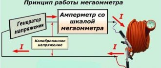
In such cases, special devices are used - megohmmeters, which measure the insulation resistance between the motor windings, cable cores, etc. The principle of operation is that a certain voltage level is applied to the object and the rated current is measured. Based on these two values, the resistance is calculated according to Ohm's law for a section of the circuit (I = U/R and R=U/I).
It is typical that megohmmeters use direct current for testing. This is due to the capacitance of the measured objects, which will pass alternating current and thereby introduce inaccuracies in the measurements.
Structurally, megaohmmeter models are usually divided into two types:
- Analog (electromechanical) - old-style megohmmeters.
Analog megohmmeter - Digital (electronic) – modern measuring devices.
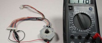
Electronic megohmmeter
Let's consider their features.
Electromechanical megohmmeter
Let's consider a simplified electrical circuit of a megohmmeter and its main elements
Simplified diagram of an electromechanical megohmmeter
Designations:
- A manual DC generator, a dynamo is used as such. As a rule, to obtain a given voltage, the rotation speed of the hand generator handle should be about two revolutions per second.
- Analog ammeter.
- An ammeter scale calibrated to indicate resistance measured in kiloohms (kOhm) and megaohm (MOhm). The calibration is based on Ohm's law.
- Resistance.
- KOhm/Mohm measurement switch.
- Clamps (output terminals) for connecting test leads. Where “Z” is the ground, “L” is the line, “E” is the screen. The latter is used when it is necessary to check the resistance against the cable shield.
The main advantage of this design is its autonomy; thanks to the use of a dynamo, the device does not require an internal or external power source. Unfortunately, this design has many weaknesses, namely:
- To display accurate data for analog instruments, it is important to minimize the mechanical impact factor, that is, the megohmmeter must remain stationary. And this is difficult to achieve by rotating the generator handle.
- The displayed data is affected by the rotational uniformity of the dynamo.
- Often the measurement process requires the efforts of two people. Moreover, one of them performs purely physical work - he rotates the handle of the generator.
- The main disadvantage of the analog scale is its nonlinearity, which also negatively affects the measurement error.
Note that in later analog megohmmeters, manufacturers abandoned the use of a dynamo, replacing it with the ability to operate from a built-in or external power source. This made it possible to get rid of characteristic shortcomings; in addition, the functionality of such devices has significantly increased, in particular, the voltage calibration range has expanded.
Modern analog model of megaohmmeter F4102
As for the principle of operation, it has remained unchanged in analog models and consists of a special gradation of the scale.
Electronic megohmmeter
The main difference between digital megohmmeters is the use of a modern microprocessor base, which can significantly expand the functionality of the devices. To obtain measurements, just set the initial parameters and then select the diagnostic mode. The result will be displayed on the information board. Since the microprocessor makes calculations based on operational data, the accuracy class of such devices is significantly higher than that of analog megohmmeters.
Separately, mention should be made of the compactness of digital megohmmeters and their versatility, for example, testing residual current devices, measuring ground resistance, phase/zero loops, etc. Thanks to this, comprehensive tests and all necessary measurements can be carried out with one device.
Test voltage standards for cables/equipment
| Operating voltage of cable/equipment | DC test voltage standards |
| 24 to 50 V | 50 to 100 VDC |
| 50 to 100 V | 100 to 250 VDC |
| 100 to 240 V | 250 to 500 V DC |
| 440 to 550 V | 500 to 1000 V DC |
| 2400 V | 1000 to 2500 V DC |
| 4100 V | 1000 to 5000 V DC |
| From 5000 to 12,000 V | 2500 to 5000 V DC |
| > 12,000 V | 5000 to 10,000 VDC |
The table above shows the recommended test voltages according to the operating voltages of installations and equipment (values taken from IEEE Guide 43-2000).
In addition, these values are specified for electrical appliances in a wide variety of local and international standards (IEC 60204, IEC 60439, IEC 60598, etc.).
In France, for example, the NFC15-100 standard provides test voltage and minimum insulation resistance values for electrical installations (500 V DC and 0.5 MΩ for rated voltages from 50 to 500 V).
However, you are strongly advised to contact the cable/equipment manufacturer for their own recommendations on the required test voltage.
Advantages of "LABSIZ"
The company carries out measurements in Moscow and the region. To order a service:
- leave a request on the website;
- answer the consultant's call;
- sign the contract - it specifies the price for insulation resistance measurements and the start date of work.
A specialist will visit the site after signing the contract. All types of tests are guaranteed. The price for measuring insulation is determined according to a single price list. Write to us and prevent short circuits today!
Safety in Insulation Testing
Before testing
A. To ensure that the test voltage is not applied to other equipment having an electrical connection to the circuit under test, the test must be performed on a disconnected, non-conducting installation.
B. Make sure the circuit is discharged. It can be discharged by short-circuiting the terminals of the equipment and/or shorting them to ground for a certain time (see discharge time).
C. If the equipment being tested is in a flammable or explosive environment, special protection is required because if the insulation is damaged, sparks may occur when the insulation is discharged (before and after testing) and during testing.
D. Due to the presence of DC voltage, which can be quite high, it is recommended that access by other personnel be restricted and personal protective equipment (such as safety gloves) suitable for working on electrical equipment be worn.
E. Use only connecting cables that are suitable for the test being performed; Make sure the cables are in good condition. At best, unsuitable cables will lead to measurement errors, but more importantly, they can be dangerous.
After testing
At the end of the test, the insulation will have accumulated significant energy which must be released before any other operations can be carried out. A simple safety rule is to allow the equipment to discharge for five times the charging time (last test time). To discharge the equipment, you can short-circuit its terminals and/or connect them to ground. All megohmmeters manufactured by Chauvin Arnoux are equipped with built-in discharge circuits that automatically ensure the required safety.
Results of work on insulation resistance measurements
Periodic electrical resistance measurements make it possible to timely assess the condition of the insulating shell and, if necessary, take measures to partially replace the wiring, which, in turn, eliminate equipment breakdowns and the possibility of a fire in the room. Verification is also required for supervisory authorities. For example, Rostekhnadzor, in the absence of a technical report and protocols with measurement results, imposes liability on the enterprise in accordance with Article 9.11 of the Code of Administrative Offenses of the Russian Federation. In addition, inspectors of the State Housing Inspectorate may require protocols of measurement results.
You should know that protocols drawn up by an electrical measuring laboratory with its own certificate of registration in Rostekhnadzor, that is, such as “MOSENERGOTEST”, are considered legally significant.
After the electrical laboratory specialists carry out resistance measurements and document all the results in the required manner, a MOSENERGOTEST employee will present the electrical laboratory’s technical report to the customer. It will include not only protocols with the results of testing the resistance of the insulating sheath of cables and wires, but also a defect sheet with comments and recommendations for eliminating defects, as well as a copy of the laboratory’s registration certificate.
If you still have questions about the work of the MOSENERGOTEST laboratory, write to us in the special feedback form on the website or call, or contact us via email. It is advisable that you voice your requirements immediately when contacting our company - this will allow us to estimate the approximate scope of work and provide you with an estimate for their implementation.
FAQ
The result of my measurements is x MOhm. This is fine?
What should the insulation resistance be? There is no single answer to this question. The exact answer to this can be provided by the equipment manufacturer or the relevant standards. For low-voltage installations, the minimum value can be considered to be 1 MOhm. For installations or equipment with higher operating voltages, a minimum value of 1 MΩ per kV can be used, while the IEEE guidelines for rotating machines specify a minimum insulation resistance of (n + 1) MΩ, where n is the operating voltage in kV .
What test leads should be used to connect the megger to the installation under test?
The wires used on megohmmeters must have specifications suitable for the measurements being made in terms of the voltages used or the quality of the insulating materials. Using inappropriate test leads may cause measurement errors or even be dangerous.
What precautions should be taken when measuring high insulation resistance?
When measuring high insulation resistance values, in addition to the safety rules stated above, the following precautions must be observed.
- Use the special G (Guard) socket (described in the dedicated section above).
- Use clean, dry wires.
- Lay the wires at a distance from each other and without contact with any objects or the floor. This will limit the possibility of leakage currents occurring in the measuring line itself.
- Do not touch or move the wires during measurement to avoid interfering capacitive effects.
- Allow the required time to stabilize the measurement.
Why don't two consecutive measurements always give the same result?
The application of high voltage creates an electric field that polarizes the insulating materials. It is important to understand that it will take a significant amount of time for insulation materials to return to their pre-test condition after testing is completed. In some cases, this may take longer than the discharge time stated above.
How do I test the insulation if I can't shut down the installation?
If it is not possible to turn off the power to the installation or equipment under test, the megger cannot be used. In some cases, it is possible to test without removing the voltage by using special clamps to measure the leakage current, but this method is much less accurate.
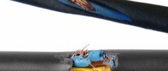
Current leakage in new conductors and its consequences
Leakage current occurs in both old and new wiring. In the first case, the cause is the natural destruction of the shell due to the end of its service life. In the second case, there may be much more reasons.
Often the conductor shell is deformed during electrical installation work Source asutpp.ru
See also: Catalog of companies that specialize in electrical work of any complexity
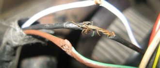
The damage is of the following mechanical nature:
- During installation - when fixing with brackets, threading through corrugation, laying in a groove.
- If the insulating layer is not properly cleaned.
- At the moment of fastening in the shield, socket, distribution box.
- As a result of careless finishing work.
A decrease in the resistance of the insulating shell leads to the appearance of a phenomenon such as current leakage. As a result, electric current from the conductor begins to penetrate the electrically conductive parts of devices, structures, structures, one way or another connected to the ground. A kind of alternative electrical circuit is formed. Only, unlike the normal one that works for the home, it only consumes electricity, and also leads to instability of the former and a high risk of such serious consequences as fire or electric shock to household members.
Advice! Checking the insulation resistance of wires and cables in your home, regardless of the frequency recommendations specified in the regulatory documentation, must be carried out at least 2 times. The first time the conductors should be checked immediately after installation, the second time - after completing the interior finishing.
Electrical insulation resistance must be performed at least 2 times - after installing the wires and after finishing the walls Source klinskiy-dom.ru
How to choose an insulation resistance meter (megger)?
When choosing an insulation resistance tester, you need to ask the following key questions:
- What is the maximum test voltage required?
- What measurement methods will be used (spot measurements, PI, DAR, DD, voltage step)?
- What is the maximum insulation resistance value that will be measured?
- How will power be supplied to the megger?
- What are the storage options for measurement results?
Insulation resistance standards for electrical circuits and installations
Standard indicators for permissible insulation resistance of electrical installations are introduced separately for each electrical facility. The requirements for this indicator differ significantly for such types of equipment as:
- Power or signal cables laid under various operating conditions.
- Operating industrial electrical installations with working wiring.
- Household appliances that have internal wiring and are equipped with a power cord.
The main indicator, the value of which is used to standardize the permissible insulation resistance, is the voltage acting in the controlled circuit. Moreover, not only its absolute value is taken into account, but also the type of power supply (single-phase or three-phase). The following is a list of some electrical devices and circuits with an indication of their corresponding insulation resistance standard:
- cable wiring located in areas and objects without deviations of climatic conditions from normal - 0.5 MOhm;
- stationary electric stoves –1 MOhm;
- switchboards with electrical wiring and cables located in them – 1 MOhm;
- electrical receivers operating at voltages up to 50 Volts - 0.3 MOhm;
- electric motors and units with a supply voltage of 100-380 Volts - at least 0.5 MOhm.
And finally, according to the PUE, for any devices connected to electrical lines with an operating voltage of up to 1 kV, this figure cannot be less than 1 MOhm. Studying the accompanying documentation for a specific sample will help determine what the resistance of the protective shell of the equipment in use should be.
Acceptable insulation resistance values
Examples of insulation resistance measurements
Insulation measurement on electrical installations, electrical equipment
Insulation measurement on a rotating machine (electric motor)
Measuring insulation on power tools
Measuring insulation on a transformer
Transformer insulation resistance is measured as follows:
a. Between high voltage winding and low voltage winding and ground
b. Between low voltage winding and high voltage winding and ground
c. Between high voltage winding and low voltage winding
d. Between high voltage winding and ground
e. Between low voltage winding and ground
When to check insulation resistance
A dielectric test of all power circuits must be carried out during commissioning. The protocol for measuring insulation resistance is one of the grounds for permitting the operation of an object. Laboratory specialists carefully check all power circuits and determine the installation resistance values. The measurements obtained give a real picture of the quality of all cable work.
The state of insulation is constantly changing; its value may be influenced by the operating conditions performed at the work site, possible emergency situations, and overload of electrical installations. Therefore, the person responsible for electrical equipment (chief power engineer, chief engineer) must draw up a periodic inspection schedule, taking into account his own electrical safety documents and the requirements of the equipment manufacturer. According to the requirements of PTEEP, it is necessary to measure insulation resistance:
- Particularly dangerous premises. The inspection is carried out at least once a year. Information about which objects can be classified into this category can be taken from the PUE. Usually these are electrical rooms, attics, technical floors, basements and rooms where boilers and boilers are installed. An accurate list of hazardous premises (according to the degree of electric shock) should be available at every enterprise. You can inexpensively order this service from electrical measuring laboratory specialists. The list of premises must coincide with the design documentation and BTI plans. Then, by a separate order for the enterprise, a special frequency is established specifically for these objects.
- Typical in terms of the level of danger of the premises. Those objects that are not included in the list of especially dangerous objects are considered ordinary. Work can be done in them at least once every 3 years. However, after any interference in the operation of devices with replacement of installation or cables, it is necessary to carry out an extraordinary check of the resistance of the dielectric sheath of the wires.
- Special purpose objects. These include catering facilities, dry cleaners, medical and educational institutions. In them, according to the requirements of the normative and technical documentation, measurements of insulation resistance should be carried out at least once a year, and for particularly dangerous premises, even more often - once every six months.
It is quite difficult to independently determine the category of premises and the frequency of cable insulation resistance measurements in Moscow - you need to use a set of regulatory documents (PUE, PTEEP, NTD) and special tables, so it is safer to contact an electrical measuring laboratory.
Choosing devices
View instruments for checking the insulation of high-voltage cables.
See also:
Why is cleaning optical connectors the most important part of working with fiber optics?
The most complete guide to choosing a twisted pair cable tester!
How do Short Circuit Indicators (SCIs) help you save time and money?