The danger of electric shock to people, damage to electrical equipment, additional load on the network and a short circuit with the possibility of fire are far from uncommon even with externally working electrical wiring. The reason for this is the thinning and loss of electrical insulating qualities of the conductor sheath. Let's look at what safety measures need to be taken in this case, what insulation resistance measurements are, how often they are carried out, why current leakage occurs and what its consequences may be, for what reasons the insulation deteriorates, what methods and instruments are used and what the instructions for taking measurements look like .
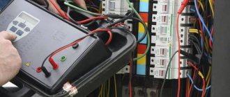
Timely checking of insulation resistance allows you to avoid an accident in the electrical network Source remkip.ru
Insulation resistance measurement - what it is, why it is carried out, frequency
The resistance of the insulating sheath of wires and cables of the electrical network characterizes the degree of protection of the outer dielectric layer from leakage or breakdown of current passing through the metal conductors. Moreover, such measurements are regularly carried out at industrial enterprises, public facilities, lighting lines, etc. The main goal is to detect current leakage and prevent serious problems.
Carrying out measurements of insulation resistance is regulated by such regulatory documents as PTEEP, POT, GOST - depending on the object/equipment and the characteristics of its power supply. The frequency of the procedure is also determined by these rules and varies from once every 6 months to 3 years. The last, longest period between inspections specifically applies to private houses. The event is officially held by representatives of Rostechnadzor or private companies with permission. The results are recorded in a special protocol.
The resistance of the insulating coating of wires is measured at least once every 3 years Source tildacdn.com
However, homeowners have much more fundamental needs for such measurements than just the requirements of the legal framework. The case concerns the safety of household members, as well as the safety of equipment, the house and adjacent objects. Thus, when a current leak occurs, the consequences may vary depending on the accompanying conditions - from frequent tripping of the RCD to a fire or electric shock to people.
Note! In order to measure the insulation resistance of electrical wiring in the house, you do not need to wait for the recommended established period - the 1st measurement every 3 years. It is necessary to pay attention to the general situation of the network. If the machine starts to operate frequently, this is the best reason to take measurements of problem areas.
Electrical measurements and control
In order to reduce the risk of fire, enterprises and organizations, regardless of their form of ownership, are required to regularly inspect the electrical network and promptly repair damaged areas. Responsibility for monitoring the condition of the electrical network rests with the chief electrician/power engineer.
In addition to regular monitoring of the state of the electrical network, each organization is required to conduct electrical measurements. Based on the results of the work performed, a report must be written that confirms the reliability and safety of the industrial power grid. All work on electrical measurements must be performed by a third-party certified laboratory.
Note! Managers and responsible persons who have not passed the Rostechnadzor inspection may be subject to administrative liability!
Current leakage in new conductors and its consequences
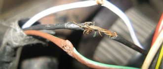
Leakage current occurs in both old and new wiring. In the first case, the cause is the natural destruction of the shell due to the end of its service life. In the second case, there may be much more reasons.
Often the conductor shell is deformed during electrical installation work Source asutpp.ru
See also: Catalog of companies that specialize in electrical work of any complexity
The damage is of the following mechanical nature:
- During installation - when fixing with brackets, threading through corrugation, laying in a groove.
- If the insulating layer is not properly cleaned.
- At the moment of fastening in the shield, socket, distribution box.
- As a result of careless finishing work.
A decrease in the resistance of the insulating shell leads to the appearance of a phenomenon such as current leakage. As a result, electric current from the conductor begins to penetrate the electrically conductive parts of devices, structures, structures, one way or another connected to the ground. A kind of alternative electrical circuit is formed. Only, unlike the normal one that works for the home, it only consumes electricity, and also leads to instability of the former and a high risk of such serious consequences as fire or electric shock to household members.
Advice! Checking the insulation resistance of wires and cables in your home, regardless of the frequency recommendations specified in the regulatory documentation, must be carried out at least 2 times. The first time the conductors should be checked immediately after installation, the second time - after completing the interior finishing.
Electrical insulation resistance must be performed at least 2 times - after installing the wires and after finishing the walls Source klinskiy-dom.ru
Causes of electrical fires
Electrical wiring faults can be reduced to two main reasons:
- physical aging. This may include damage resulting from long-term use, wear and destruction of chain components;
- obsolescence: associated with technological progress, which has made equipment that was still in good working order obsolete and irrelevant.
There is a risk of fire due to a faulty electrical circuit. The cause of the fire is:
- Poor contacts At the junction of the wires, due to oxidation of the metal and mechanical weakening of the compression of the contacts, increased resistance occurs. When current flows through the problem area, heat is generated. When the current and resistance parameters are high, energy is released that can lead to ignition of the assembly as a whole.
- Damaged electrical switches or installation of overrated switches When the maximum permissible current occurs in the network, the switch does not operate, which leads to a short circuit in the network and subsequent fire.
Reasons for deterioration of insulation
There are the following number of reasons for the decrease in the resistance value of the insulating layer:
- Initially, poor quality of the shell material, manufacturing defects.
- Damage during electrical installation work.
- Deformation under the influence of tools and materials used for finishing.
- Under the influence of overheating, when the metal core heats up when connecting powerful devices, and the coating cracks, melts, and dries out.
- During freezing and thawing of soil masses, when the cable is laid in the ground.
- Exposure to environmental factors - sunlight, temperature changes, precipitation.
- Long-term operation.
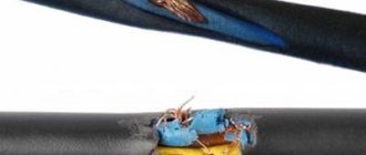
Important! The most common cause of sheath damage is careless conductor fastening. The slightest contact with sharp edges of nail heads, screws, installation tools, as well as pulling wires through cable channels is accompanied by damage to the coating. Therefore, the frequency of measuring the insulation resistance of electrical wiring should correspond to the frequency of electrical installation work.
The inclusion of powerful electrical appliances in the network is a common cause of degradation of the insulating sheath of wires Source otoplenie-gid.ru
Electrical laboratory. Functions and Features
The electrical laboratory is an independent institution whose employees have the right to conduct electrical measurements, measurements, inspect wiring and provide their assessment of the safety of the enterprise's electrical network. The organization regularly confirms its right to provide electrical measurement services by obtaining a certificate from Rostechnadzor.
During the inspection it is confirmed:
- qualifications of laboratory staff;
- equipment performance;
- the right to conduct research on electrical equipment and networks.
ETL equipment is regularly tested for the accuracy and reliability of the data obtained, and technical reports and the content of test or measurement results are confirmed by Rostekhnadzor inspections and, in the event of force majeure, are accepted by the court as evidence.
The electrical laboratory is truly an independent expert and can provide objective data on the performance of the electrical network of each business facility.
What is the work of the laboratory
Scheduled measurements should be carried out according to the algorithm developed by Rostechnadzor, but no less than once every three years. Without a report on a scheduled inspection, an enterprise may be fined, and in the event of a repeated violation, its work is in most cases suspended. To avoid difficulties associated with forced downtime, managers of enterprises and organizations can enter into an agreement with ETL for regular monitoring of the condition of electrical networks. The results of a scheduled inspection of the condition of electrical networks will be presented in a technical report, which is provided to the management of the enterprise.
Unscheduled inspection and electrical measurements are necessary in the following cases:
- major repairs, redevelopment of the building;
- liquidation of consequences of an emergency situation (fire, flood);
- taking office electrician or ch. energy;
- before selling or renting the premises of the enterprise;
- emergency event (short circuit, protection failure);
- at the request of the manager.
Who orders electrical laboratory services?
The customers are:
- commercial and industrial enterprises;
- construction organizations delivering turnkey projects;
- general education, municipal organizations;
- financial institutions;
- military facilities (small towns, training grounds, bases); scientific research centers;
- research centers and others.
The electrical laboratory does not provide services to private individuals due to the low household load on the electrical grid.
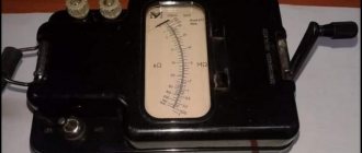
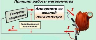
Methods and instruments for testing
In order to measure the resistance value of the conductor coating, a specialized device is used - a megohmmeter. For home electrical networks, the nominal value of which ranges from 220-380 V, the procedure is carried out within 500 V. In this case, the minimum value of the measured indicator should not be less than 500 kOhm, or 0.5 MOhm. Otherwise, this will mean that the insulation is broken and the conductor in this part of the circuit needs to be replaced.
The resistance of the electrical network in a private house is measured either between current-carrying conductors, or between each specific wire and the ground loop. The following measurement options are available:
- Phase – working zero.
- Phase – ground loop (PE).
- Phase – phase.
- The working zero is the ground loop (PE).
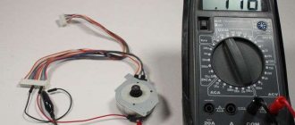
Such a universal device as a multimeter also has the ability to measure resistance. However, the function is intended to take readings of the electrical circuit itself, and not of the insulating sheath of the conductor. Therefore, in the case under consideration it is not applicable.
Algorithm for interaction with the laboratory
Before starting work, you must consult with a company employee and determine exactly what laboratory services you need. For routine monitoring of the operation of the electrical network, a contract is concluded for certain types of services - and after repairs, it may be necessary to conduct extended tests. The list of services will necessarily be specified in the agreement signed between the enterprise and ETL. The cost of the work and the date of measurements will also be indicated there. On the appointed day, ETL representatives visit the site and take the necessary measurements. Laboratory employees must be granted access to any premises of the institution. Based on the results of the work, a technical report is drawn up on the condition of the electrical equipment and network of the enterprise.
Instructions for taking measurements
In order to measure the sheath resistance of home wiring, you must follow the following instructions:
- Conduct a visual inspection of the network.
- Unplug all devices from the sockets, turn off the RCD and circuit breakers.
- The terminals are connected to the phase and zero of the input panel, and measurements are taken.
- Next, all groups are checked separately.
- Before moving on to measuring the next group, the charge is first removed from the ohmmeter.
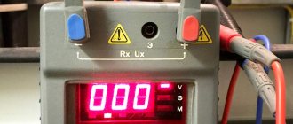
When measuring the insulation resistance of home electrical wiring, the readings should tend to the infinity edge of the instrument scale. The minimum acceptable value is 0.5 MOhm. If less, it means there is a current leak and the conductor will need to be replaced.
Registration of test results
All tests and measurements in electrical installations are carefully documented. Papers must be stored and provided to inspection authorities upon request. The report includes:
- Test program approved by the consumer management.
- Single line diagram.
- Certificate of the work contractor, containing certified copies of licenses, laboratory registration certificates.
- Protocols:
- conducting a visual inspection;
- test activities, according to the approved form.
- Defective statement.
Important: reporting documentation must be stored together with the equipment passport (the norm is contained in clause 3.6.13. PTEEP).
Briefly about the main thing
The resistance of the wire's insulating sheath determines the level of protection against electric current breakdown. The frequency of parameter measurement is subject to PTEEP, POT and GOST standards, depending on operating conditions and characteristics of electrical networks. Measuring the resistance of a home network allows you to detect leakage current in time and prevent destructive consequences.
Current breakdown can occur both in old conductors - due to natural deterioration of the sheath, and in new ones - primarily due to mechanical damage during careless installation. Among the most common reasons for a decrease in insulation resistance are the following:
- Poor quality coating.
- Damage during installation.
- Destruction during wall finishing.
- Overheating under heavy network load.
- Impact of natural environmental factors.
- Long-term operation.
The frequency of measuring the insulation resistance of internal home or external networks for powering lighting systems, equipment and various installations in the local area is once every 3 years. However, for safety reasons, the procedure must be carried out every time after electrical installation work and finishing. Measurements are carried out with a megohmmeter between live wires or conductors and the ground loop according to the instructions. The reading of the device in the normal state of the insulating coating should be at least 0.5 MOhm.
General checks and tests of electrical equipment Stages and organization of commissioning work
The commissioning work can be divided into eight stages, differing in the technology of their implementation.
- Pre-installation inspection and testing of equipment: machines and mechanisms, devices, fittings, controls and information presentation.
- Element-by-element acceptance from installation and individual testing of equipment.
- Unit-by-unit acceptance from individual tests (including the necessary control of completeness and quality of installation) of equipment of functional units. In accordance with SNiP 3.05.05-84, SNiP 3.05.06-85 and SNiP 3.05.07-85, the stages of element-by-element acceptance from installation and individual testing of equipment do not coincide in time for different types of equipment and this difference can be very significant. Unit acceptance serves to check the readiness of all types of unit equipment for unit adjustment at the time of its start.
- Unit-by-unit start-up (hereinafter referred to as “start-up”) adjustment of functional units on idle equipment (cold adjustment) and testing them under load. Transferring functional units from commissioning to operation mode, to checking construction and installation readiness and to unit-by-unit complex adjustment on operating equipment.
- Testing of a unit (or a separate boiler unit, turbine unit) with synchronization (or without it for a separate boiler unit) and a load set to check its full construction and installation readiness.
- Unit-by-unit integrated (hereinafter referred to as “integrated”) adjustment and testing of functional units, including subsystems of automated process control systems and the operational circuit of the block control panel for testing equipment modes. Trial operation of functional and technological units, including monitoring and control systems, identification and elimination of defects, transfer of functional units to industrial operation. Carrying out a comprehensive testing of the unit (installation).
- Acceptance of the unit (installation) into operation by the state commission, carrying out the necessary tests of power equipment and issuing the corresponding act.
- Two fundamentally different types of organization of commissioning work on equipment are provided: work carried out by specialists of one profession (thermal mechanics, electricians, process control system specialists, etc.) who perform commissioning operations almost independently of specialists of other professions.
The first type of work organization is used:
- during pre-installation inspection, inspection, element-by-element acceptance from installation and individual testing of equipment;
- at the initial stage of complex adjustment of units, when it is advisable to carry out initial assurance of the reliability of equipment operation in the designed volume separately by its type.
Starting from the stage of unit-by-unit acceptance from individual testing and until the acceptance of the unit (installation) by the state commission (with the exception of the initial stage of complex adjustment), commissioning and commissioning is carried out by unit teams and organized by complex working subcommittees.
The preparatory stage of commissioning begins after the release of working drawings. At this stage:
- study and analysis of design and factory documentation, determination of compliance of design documentation with regulatory documents, standard solutions and best practices, development of comments and recommendations for eliminating deficiencies;
- drawing up a project for commissioning work, including safety measures;
- development and approval of work programs for commissioning and commissioning of equipment;
- preparing a fleet of measuring equipment, testing equipment and devices, organizing and equipping an on-site laboratory, providing workplaces with instruments, tools and instructional materials;
- compiling a list of documentation, the execution of which is necessary at various stages of production and acceptance of commissioning work at each functional unit.
After completing the complex adjustment of a power unit or individual unit and its comprehensive testing, the said equipment is accepted into operation. Acceptance for operation is carried out with the appointment, if necessary, of control sampling and testing.
A comprehensive check of all subsystems of the automated process control system is also carried out, checking the joint operation of the main units and auxiliary equipment at the maximum possible load, checking the operating modes of the turbine unit, generator, transformer and auxiliary equipment when operating on the main fuel and control algorithms for functional units in stationary and variable modes;
Production of adjustment work
When setting up TU-TS-VTI devices, the setup personnel performs the following work: inspection of the equipment; measuring the insulation resistance of equipment and communication lines: setting each element of the circuit to a given mode, determined by the technical conditions and design data of the project; checking the correct interaction of all elements of the circuit; checking the operation of TM devices together with the control panel and console; training of TM devices; putting TM devices into normal operation; preparation and submission of reporting documentation.
All units and units of devices are subject to inspection. At the same time, the quality and correctness of installation, compliance of the equipment with passport data, type of equipment, device models, year of manufacture, serial number, and device capacity are checked. If design and installation defects are identified, appropriate corrections or additions must be made.
The insulation resistance is measured with a 500 V megohmmeter between the output terminals of the half-sets connected together and the housing. The insulation resistance value must be no less than that specified in the technical description for this type of device. When setting up circuit elements, you must be guided by technical descriptions and setup instructions from manufacturers. It is necessary to ensure that the parameters of all individual elements, nodes, and blocks correspond to the specified modes.
After setting up individual circuit elements, the correct interaction of circuit elements, the passage of TU, TS, VTI signals, and the operation of protective and control units in case of damage to the device or communication line are checked.
Next, the operation of the device is checked together with the control panel and console during all telemechanical operations and when the supply voltage changes within the limits established by the technical data for a specific device.
The device is trained for one month. At the same time, the following is checked: the passage of the alarm, for which notification series of all signal relays are sent from the control panel, either one or several at once; passing control commands and calling telemetry; operation of protective units. Checking the passage of alarm series, commands and the operation of protective units should be carried out 3 times a day.
Connecting external connections on the gearbox to the terminals of the half-set must be done after completing the training of the device. In this case, each individual signaling, control or telemetry call circuit is carefully dialed, marked and connected to the terminals of the semi-set according to the design. After this, the TM device is put into operation, which is confirmed by the relevant protocol and act.
Testing of telemetering devices is carried out in two stages: laboratory tests and tests after installation of the devices at the place of work. Laboratory tests are usually performed in a factory laboratory.
First, the devices included in the device are checked, each individually, and then according to the block diagram of the device - complete with communication channel equipment. Laboratory tests are carried out in the following scope: checking the markings of devices and completeness; measuring the insulation resistance of devices in relation to the housing with a 500 V megohmmeter; determination of the main error
conversion and adjustment, if necessary, of devices; determination of the main telemetry error of the device.
Tests after installation at the place of work include: external inspection and verification of compliance of the equipment with technical documentation; measuring the insulation resistance of the entire system; measurement of communication line parameters; determining the main telemetry error and, if necessary, adjusting the equipment; trial operation for at least 48 hours. After unpacking the telemetering devices (converters, receiving devices), an external inspection is carried out, which reveals defects that impede normal operation. Then check the insulation resistance of the converter with a 500 V megohmmeter type Ml-101. Before starting measurements, it is necessary to clean the transducers from dust. The megohmmeter is connected with one clamp to the housing, and the other to the pre-shorted terminals of the converter. When measuring, only clamps “L” and “3” are used. Before measurements, as a rule, the resistance of the megohmmeter wires is checked, and the readings on the scale are checked with open and short-circuited wires. When checking the insulation resistance, it is necessary to carefully monitor the place where the wires are connected so as not to apply a voltage of 500 V to the circuit elements. It is customary to measure the insulation resistance 60 s after the start of measurements.
External inspection and verification of compliance of the equipment with technical documentation after installation of the TI device consists of checking the correct installation, compliance of the markings with the installation diagrams and the completeness of the devices with technical documentation. (Testing the LC consists of checking the markings, measuring the insulation resistance both between the cores and to the ground, with a megohmmeter for a voltage of 500 In and measurement of ohmic resistance. To measure ohmic resistance, the communication line is disconnected from the primary converter and the receiving device. On the PU or CP side, a jumper is placed on the terminals, and then on the opposite side, the resistance is measured with a device (for example, an ohmmeter). Values of insulation resistance and ohmic resistance must be within acceptable limits.The insulation resistance must be equal to or higher than that specified in the passport.
The role of grounding and insulation of the electrical network
Grounding is the connection of electrical devices to the ground mass for protection against electric shock. If the device does not work properly, grounding can save a person. The simplest ground electrode is a metal rod, but in some cases it can be complex elements of various configurations.
When checking the quality of grounding, resistance measurements are made on the ground loop. If such equipment checks are carried out regularly and the condition of the ground electrode is monitored, then you can see whether the equipment is reliably isolated from voltage surges.
Electrical measuring measures when testing electrical networks
A breakdown of cable insulation or a significant voltage surge can cause failure of expensive equipment, fire, accident and other negative consequences. To prevent them, you need to timely test the power supply system:
- measurements of voltage in the electrical network, insulation resistance, ground loop;
- temperature control of cables, wire cores and busbars in contact areas;
- checking automatic installation machines of power supply lines;
- monitoring of RCDs, lightning protection systems, fuses;
- checking the condition of cable lines;
- monitoring the presence of markings, warnings and other inscriptions;
- determining the resistance of the phase-zero loop for the most remote section;
- checking the state of connection of electrical network devices to the ground loop.
After diagnostics, measurements and tests of electrical equipment, search and identification of faults, recommendations are issued for the modernization and repair of electrical networks.
Timing of electrical tests
There are no specific deadlines for submitting a technical report (TR) on tests. But the laboratory of electrical measurements, as a responsible executor, submits maintenance and related documents strictly on the date specified in the contract. The usual period for compiling a report lasts 2-3 business days, in some cases (complex equipment, large volumes of work), the period for compiling will be extended. For small power plants and electrical networks of small buildings, ETL presents the test results the very next day. An urgent examination of the condition of the power plant and electrical wiring is also possible at the request of the customer.
The contract may stipulate conditions for testing: night time, non-working days, etc. This is done so as not to affect the workflow or reduce production volumes.
Types of electrical network tests
Upon completion of electrical installation work at an enterprise or other facility, acceptance tests are immediately carried out. The results of the measurements taken are entered into a technical report, without which it is impossible to put the system into operation.
In accordance with the requirements of supervisory authorities, periodic tests of electrical networks are carried out. The frequency of their implementation is indicated in the regulatory documentation and depends on the technical features of electrical installations, equipment and networks.
Preventative testing is performed to prevent various malfunctions, short circuits, wiring fires, and non-compliance of electrical equipment with regulatory requirements.
What types of tests does the electrical measuring laboratory perform?
Tests and measurements carried out by the electrical measuring laboratory can be divided into the following types:
- acceptance tests - such tests are carried out when a facility or new equipment is put into operation, they are regulated by the PUE and are needed to assess the quality of electrical installation work and their compliance with project documentation;
- operational – are carried out to ensure control of equipment in operation, since electrical parameters can, under the influence of various factors, deteriorate over time and negatively affect the fire safety and electrical safety of the facility, all testing requirements are regulated by PTEEP;
- control - carried out when there is a need for an extraordinary check of the condition of electrical installations; they are carried out at the request of the customer after emergencies or other emergencies occur at the site;
- comparative - carried out in cases where the customer is not sure that the data on the state of electrical installations indicated in the technical report corresponds to reality and wants to check and confirm this.
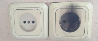
Checking grounding in a regular outlet
The presence of a grounding contact on an electrical outlet does not mean that it is grounded. Several methods can be used to check insulation and grounding. To check grounding and insulation, you will need a multimeter with a screwdriver, as well as a voltage indicator.
The phase of the socket can be determined with a tester. After this, check the contact with the indicator: if it lights up, the socket is faulty or incorrectly connected.
Then you need to turn off the machines and remove the electrical outlet, and before that make sure that three wires are connected to the outlet. When performing this sequence of actions, the socket is returned to its place, then the machines are connected and the test with a multimeter continues. How to check with a multimeter:
- First, the voltage between zero and phase is checked. If there is no voltage, then the neutral wire is broken
- further – between the ground and the phase. In this situation, there may be no voltage if there is no ground connection.
- and finally - between the ground and zero. The absence of voltage in this combination indicates zeroing
If you have not previously had to check ground insulation yourself, read the detailed instructions and consult with specialists.
remont.youdo.com
Contact the professionals!
offers its services for carrying out various electrical measurements with the issuance of protocols for measuring insulation resistance, grounding, phase-zero loops and a technical report of the appropriate sample. We have a license to carry out this type of work and a mobile electrical measuring laboratory registered with Rostekhnadzor. We carry out a full range of work to check the technical condition of electrical networks and equipment at facilities of any scale and purpose!
For detailed information, call tel. 8-800-707-22-14
or fill out the online application form.
Before ordering insulation resistance measurements
and other electrical laboratory services, you can receive comprehensive advice from our qualified specialists on the current requirements for electrical measurements and an approximate calculation of the cost of services.
Remember! Maintaining electrical networks, pantographs and electrical distribution devices in good condition is the key to the fire safety of the facility and its efficient operation!
To achieve this, we will offer the most cost-effective and technically sound solution. After completing the measurements, specialists provide a certificate of work performed and a full package of documents: protocols for electrical measurements and visual inspection, a technical report, a load map, a list of defects and a conclusion.
We guarantee a high level of service and optimal prices!
msc01.ru