The protocol for measuring insulation resistance in a single-phase network is filled out by electrical laboratories and other organizations whose activities are related to electrical installation work. It is necessary for drawing up an insulation resistance measurement report and is the basis for filling out its data.
- Form and sample
- Online viewing
- Free download
- Safely
FILES
This document is also part of the technical report on electrical measurements. Electrical engineering companies of various types can thus sum up the results of their work and report to customers or higher authorities on the conduct of relevant research.
Different types of measurements
Protocols for measuring the insulation resistance of single-phase and three-phase circuits look different.
For a single-phase circuit, three measurements are sufficient; for a three-phase circuit there should be ten (if it is five-wire).
For this reason, documents for different circuits have different appearances. Although they may be identical in appearance, the “filling” of the wire (and devices corresponding to the voltage being conducted, for example, RCDs) affects what kind of paper will be filled.
You should also pay attention to the differences in the requirements for resistance and voltage in conductors with different cross-sections of conductors.
Why is insulation resistance measured?
In this article I will try to answer all the questions related to this type of test, if suddenly there are any questions, they can be written in the comments under the article. Below is a list of topics that the article is divided into, they are also links to the part of the page where this is discussed.
- Why is insulation resistance measured?
- Who can request a protocol or conduct tests;
- Work order;
- What instruments are used to measure;
- Test frequency;
- What documents regulate testing;
- Acceptable insulation resistance values;
- Sample protocol.
Why is insulation resistance measured?
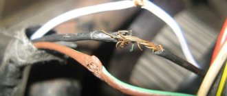
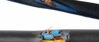
This type of electrical measuring work is one of the most basic. It is carried out in order to identify manufacturing defects in the cable, damage that occurred during the installation of the cable, as well as its careless operation. As insulation ages over time, its properties deteriorate. If the cable was repeatedly overloaded during operation or short circuits occurred on the line, this also negatively affects the service life of the insulating layer. In fact, testing allows you to prevent dire consequences, such as:
- Fire caused by a short circuit;
- Electrical shock to people, which can be fatal;
- Failure of electrical equipment, especially sensitive microelectronics;
It is good practice to check the cable in the coil or on the drum before laying it, in order to avoid inconvenient situations associated with manufacturing defects. It is especially sad to lay a fairly large piece of bad cable, large weight and cross-section.
Who can request a protocol or conduct tests
As a rule, the following services require the coveted piece of paper or a protocol:
- Administration or service of the chief power engineer of shopping and business centers;
- A management company that manages residential or non-residential real estate, HOAs, SNTs, etc.;
- The Customer or General Contractor for electrical installation work or the technical supervision hired by him to check that everything is done correctly before the final payment has been made;
- When inspecting objects in operation, a firefighter or an inspector from the Ministry of Emergency Situations may require;
- When commissioning large facilities - a representative of Rostechnadzor;
- Insurance company, when insuring real estate, especially large objects such as warehouses.
Work order.
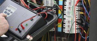
The real test is carried out with the load completely disconnected, since otherwise nothing will work; even a telephone charger plugged into the socket will not allow the test to be completed. Regardless of the type of object, such work is planned in advance so that the customer can provide access to all premises and the ability to disconnect all electrical appliances, including disconnecting lamps, from the supply line. Let's consider the procedure for carrying out work using the example of a small office center consisting of an ASU, several floors with electrical distribution panels. As a rule, it all starts with measuring the main lines from the building's ASU to the electrical distribution panels. Next, from the electrical distribution panels, the power lines for sockets and lighting, as well as other electrical equipment, are checked.
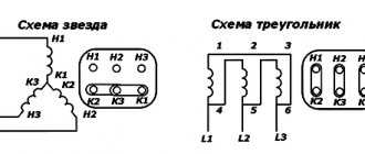
Each line is measured for 1 minute. If the line is 3-wire (220V), then 3 measurements are made: phase conductor - relative to the neutral one, phase conductor - relative to the grounding one, zero relative to the grounding one. If the line is 5-wire (380V), then much more measurements are made, namely 10: phase1 - phase2, phase1 - phase3, phase2 - phase3, phase1 - zero, phase2 - zero, phase3 - zero, then also each phase conductor relative to the grounding (PE), as well as zero relative to it. The actual work requires quite a lot of time.
What instruments are used to measure
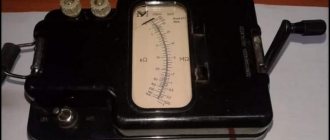
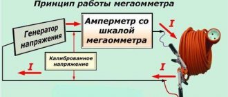
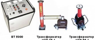
Since insulation resistance is determined in megaohms (Mohm), a special device, a megohmmeter, is used for measurements. Such a device is available in every electrical measuring laboratory, even in large electrical installation organizations. It can be either combined, which has functions for other measurements, or as a separate device such as:
- E6-24;
- ES0202/2G;
- MI 3121H.
For official testing, it is necessary that the device is in the state register and also has a valid verification. Naturally, in an electrical laboratory that checks objects every day, there are no problems with this. For an electrical installation organization that checks only for itself, for example, a cable after installing a coupling, after or before laying, any working megohmmeter will be sufficient, since they do not need to submit an official report.
Test frequency;
The frequency of work is prescribed in the PTEEP. For the main objects it is as follows:
- When commissioning the facility;
- On cranes and elevators - at least once a year;
- Stationary electric stoves - at least once a year;
- In particularly hazardous rooms and outdoor electrical installations - at least once a year;
- In all other cases - at least once every 3 years;
Despite the frequency described above, if you are a tenant, then of course you need to look at the lease agreement, it may stipulate a different frequency and the test program itself; often the administration of shopping centers sets the frequency once a year, even if you do not have premises related to especially dangerous, also requires mandatory thermal imaging inspection of electrical panels and updating of single-line diagrams. Naturally, no one forbids carrying out inspections more often, it will only be better, but for missing a check you can get a fine, even with the suspension of activities, at the discretion of the inspector.
What documents regulate testing?
PTEEP, GOST 50571 test section, Article 9.11 of the Administrative Code of the Russian Federation. PUE. Technical regulations of lessors, RD 34.45-51.300-97 scope and standards for testing electrical equipment.
Acceptable insulation resistance values
- General purpose electrical wiring - at least 0.5 Mohm;
- Control circuits - at least 1 Mohm;
- Cranes, elevators, electric stoves, stator windings of electric motors - at least 1 Mohm;
If the device readings were no more than 1 MΩ, then it is necessary to test the cable with increased voltage of industrial frequency 50 (Hz).
In reality, megohmmeter readings from 5 megohm and below, while changing sharply during the measurement process, are practically shooting through in some place in the cable, this can be clearly seen in the video at the end of the article.
Sample protocol
I am attaching a sample protocol, as well as a picture.
In any case, in reality the situation is such that if any emergency situations occur, especially a fire, as a rule they begin to raise documents and check whether the insulation resistance was measured in a timely manner and if it was not, then this is one of the options to blame everything on it.
Naturally, checking the insulation alone is not enough; it is advisable to check the object comprehensively, since in the event of a short circuit it is important that the circuit breaker operates instantly (0.4 seconds for group networks). To do this, the resistance of the phase-zero loop is measured.
Components of a protocol
The document is filled out on one side of the sheet. In the upper part on the left is the full name of the measurement contractor with address data. Information in the same format about the customer is also required. Below in the form is the name of the agreement. Next to it is the document number entered in the registers. The date of signature is also indicated here.
For the convenience of providing information, specific data on cables and their conductivity, according to measurements, are presented in the form of two tables. The first has the following columns:
- Serial number.
- The name of the accession.
- Cable brand, number of cores, their cross-section. If possible, it is necessary to indicate whether there is insulation on the cable cores and what material the conductor is made of (the default is copper, but there are also options for conductors with an outer copper sheath and an internal aluminum content). If a wire is examined for resistance, then you also need to indicate how many wires it has and whether it is insulated.
- Insulation resistance in L–N core.
- Insulation resistance in L–PE.
- Insulation resistance in N–PE.
- Conclusion on compliance. Here we mean meeting the requirements of PUE clause 1.8.37 (7th ed.) for electrical wiring and PUE clause 1.8.40 (7th ed.) for cable lines.
The second describes the equipment used for measurements and consists of columns with information such as:
- serial number;
- device name;
- type;
- factory number;
- range of available measurements;
- basic error;
- certificate number;
- date of last check;
- date of the next device check.
Both tables can contain one or several rows. Measurements cannot be carried out without equipment at all, so filling out the second table if the document exists is mandatory. At the very end of the tables, the regulatory document must be indicated (GOST, PUE, SaNPiN, PTEEP, instructions RD and SO., etc.), for compliance with which the insulation of a specific single-phase circuit was tested. Based on these tables and the information found in the documents, a conclusion must be made: whether the conductor insulation meets the stated requirements or not. It is formulated in writing, in a special column “Conclusion”. The form provides only one line for this, since one word or sentence “complies” or “does not correspond” will be enough.
As-built documentation
Download different protocols for construction:
Protocols over communication networks:
1 Protocol for measuring the OB attenuation of mounted cables in regeneration areas, example,
2 Protocol for measuring the insulation resistance of the outer polyethylene shell of the FOC (armored cover - “earth”) at the installed regeneration section, form,
3 DC cable measurement protocol, example,
4 Optical crossover installation protocol, example,
5 Optical coupling installation protocol, example,
6 Protocol for incoming inspection of building lengths OK, example.
7 OK control protocol after installation, example
8 Balanced cable testing protocol (form 16 MVLKS), form,
9 Protocol for testing coaxial cable type KM-4, MKT-4 (form 17 MVLKS), form,
10 Protocol for electrical measurements of security at the far end (Form 6 MVLKS), form,
11 Protocol of electrical measurements with direct current of single-coaxial cable type VKPA (form 11 MVLKS), form,
12 Protocol of electrical measurements with direct current of coaxial cable type KM-4 (Form 9 MVLKS), form,
13 Protocol of electrical measurements with direct current of small-sized coaxial cable type MKT-4 (form 10 MVLKS), form,
14 Protocol of electrical measurements of a symmetrical cable with direct current (form 4 MVLKS), form,
15 Protocol for electrical measurements of transient attenuation at the near end (Form 5 MVLKS), form,
16 Protocol for measurements of cable transient attenuation, form,
17 Protocol for measuring potentials on the cable sheath (Form 7 MVLKS), form,
18 UTP cable measurement protocol - twisted pair, example, .
19 Measuring protocol for RG coaxial cable, example,
20 Measurement protocol for UNITRONIC LIHCH 16x2 cable, example,
21 Protocol for measuring cables with direct current (for copper cables such as TPP), form,
22 Protocol for measuring cable lines restored using UVK-MM2, example
,
23 Protocol for measuring the construction length of a fiber-optic cable after installation, form,
24 Protocol for measuring the construction length of a fiber-optic cable after installation, example
,
25 Protocol for input control of the construction length of the fiber optic cable FOC, example,
26 Optical splitter measurement protocol, example,
27 Protocol for checking the presence of a circuit between groundings, grounded installations and elements of grounded installations, example
,
28 Protocol for measuring the insulation resistance of the outer polyethylene shell of the FOC (armored cover - ground) at the installed regeneration site, example
,
29 Protocol for checking the measurement of attenuation of the regeneration section with an optical tester, example
,
30 Test report for compatibility when splicing optical fibers from different manufacturers, example,
Protocol for electrical installation work:
1 Protocol for measuring the resistance of grounding devices, form,
2 Protocol for testing the resistance of grounding conductors and grounding devices, example 1,
3 Protocol for testing the resistance of grounding conductors and grounding devices, example 2 +,
4 Protocol for testing the resistance of grounding conductors and grounding devices, example 3
+
,
5 Protocol for testing the resistance of grounding conductors and grounding devices, example 4
+
,
6 Power cable test report, example
+ ,
7 Protocol for measuring insulation resistance, form,
8 Protocol for measuring insulation resistance, example + ,
9 Protocol for checking the insulation resistance of wires and cables, example 1,
10 Protocol for checking the insulation resistance of wires and cables, example 2
+
+
,
11 Protocol for checking the insulation resistance of wires, cables and windings, example 3 +,
12 Protocol for inspection and checking the insulation resistance of cables on a drum before installation, example,
13 Insulation test report for increased AC voltage, example + ,
14 Protocol for checking the impedance of the phase-zero loop, form,
15 Protocol for checking the phase-zero circuit in electrical installations with voltages up to 1000V with solid grounding of the neutral, example 1,
16 Protocol for testing the phase-zero circuit in electrical installations with voltages up to 1000V with solid grounding of the neutral, example 2
,
17 Protocol for checking the circuit between grounding conductors and grounded elements, example 1,
18 Protocol for checking the circuit between grounded installations and elements of a grounded installation, example
+
,
19 Protocol for checking the circuit between grounding conductors and grounded elements, example 2
+ ,
20 Protocol for checking the conditions for triggering the RCD, form,
21 Protocol for testing instantaneous releases of automatic circuit breakers in electrical installations with voltages up to 1000V, example 1,
22 Protocol for testing instantaneous releases of automatic circuit breakers in electrical installations with voltages up to 1000V, example 2
+
+
,
23 Protocol for testing an electric gas switch and setting up devices, example ++
,
24 Circuit breaker test report, example
+ ,
25 Test protocol for circuit breakers, example
+
,
26 Test report for power transformer, example 1
+
,
27 Test report for power transformer, example 2,
28 Power transformer test report, example 3
+++,
29 Battery voltage measurement protocol, example
,
30 Protocol for measuring battery insulation resistance, example,
31 Test report for increased AC voltage, example,
32 Test protocol for arresters and arresters, example,
33 Test report for testing a 10kV power cable line, example
+
,
34 Acceptance test report for cable AVBbShv 4x70, example
35 Acceptance test report for cable AVBbShv 4x185, example, .
36 Acceptance test report for cable AVBbShv 4x240, example,
37 Protocol for visual inspection of an electrical installation, example +
,
38 Protocol for visual inspection of electrical installations, example
+
+
,
39 Test report for cable line terminations, example
+,
40 Protocol for the presence and quality of connections between equipment and a grounding device, example +
,
41 Test report for busbars and connecting busbars, example
+
,
42 Cable line test report, example
+,
43 Test report for cable lines up to 1000V, example
+,
44 Protocol for checking the secondary switching of the cabinet, example +
+
,
45 Low voltage assembly test report, example +
,
Fire alarm protocol:
1 Protocol for heating cables on reels, form,
Protocol for installation of elevators:
1 Protocol for checking the operation of the elevator, form,
2 Test and measurement report for a full technical examination of the elevator (from an accredited testing laboratory), form,
3 Protocol for checking the technical documentation for the elevator (from an accredited testing laboratory), form,
Protocol of Russian Railways (railroads):
1 Test report for bushings, form,
2 Protocol for checking differential protection with RNT series relays, form,
3 Test report for single-phase voltage transformer, form,
4 Test report for three-phase voltage transformer, form,
5 Test report for oil-filled current transformer, form,
6 Test report for disconnector, form,
7 Test report for tubular arresters, form,
8 Power transformer test report, form,
9 Dry reactor test report, form,
10 Protocol for checking the impedance of the phase-zero loop, form,
11 Protocol of acceptance and preventive tests of the generator installed at the power plant, form,
12 Protocol for adjustment and testing of oil switch, form,
13 Test report for solid insulation current transformer (built-in), form ,
14 Cable test report, form,
15 Test report for support, suspension, bushing insulators, form,
16 Test report for the resistance to spreading of the ground loop, form ,
17 Protocol for checking the presence of a circuit between grounding conductors and grounded elements, form,
18 Test report for valve arresters and surge suppressors, form,
19 Insulation test report in switchgear, form,
20 Test report for mechanic belts, claws, belts, form,
21 Test report for voltage indicators, form,
22 Test report for voltage indicator for phasing, form,
23 Test report for insulating rods, clamps, form,
24 Test report for protective equipment made of dielectric rubber (gloves, galoshes, boots), form,
25 Test report for tools with insulated handles, form,
26 Oil test and analysis report, form,
27 Test report for the filter device of a traction substation, form,
28 Protocol for checking earth protection of 6-10 kV connections, form,
29 Test report for high-speed circuit breaker, form,
30 Protocol for testing differential protection with relays of the DZT-10 series, form,
31 Semiconductor converter test report, form,
Protocol on civil works:
1 Report of the results of radiographic testing of welded joints, form,
2 Report of mechanical tests of welded joints, form,
3 Report of the results of ultrasonic testing of welded joints, form,
4 Drilling protocol, form
5 Test report for control concrete samples for compressive strength, example
,
6 Soil sampling protocol, example
+
,
7 Protocol for determining the degree of soil compaction, example with appendix,
8 Protocol for determining the degree of sand compaction, example with appendix,
9 Test protocol for concrete cube samples, example,
10 Core test report example,
11 Protocol for drilling a well using the HDD method, form,
Return to the section: “Acts, protocol diagrams, etc.”
See the composition of the executive in the section: “Composition of the executive”
Download acts, protocols and more in the section: “Acts and other”
Download useful books, GOSTs, SNIPs in the section: “GOSTs and books“
Who makes the measurements
An important role is played by who carried out the resistance measurements. The protocol will not have legal force if the employees of the institution who compose and fill it out do not have the appropriate qualifications for this occupation.
Important! A specially trained electrical engineer takes measurements, checks against regulations and signs at the end to ensure that the information is correct.
Also, after the conclusion, the testing engineer and the head of the laboratory must sign. Then everything is certified by the seal of the institution that carried out the measurements. It is worth noting that, at the request of the customer, many electrical laboratories can draw up defect reports (if the inspection reveals faults in any single-phase circuit equipment) and provide a service to eliminate the identified shortcomings and problems.