When it comes to transformers and their types, all models still have similar functionality; the only way transformers can differ from each other is the scope of application and the materials chosen to complete the product. In the assortment of power elements, the toroidal transformer, characterized by successful design capabilities and good performance, takes pride of place. And the most important difference between a toroidal transformer and all other types is that the core or magnetic circuit of the product is formed in the form of a ring. However, we will consider all other technical advantages and areas of application further in more detail in the article.
What are the purpose and functionality of toroidal transformers?
- power and measuring;
- increasing or decreasing.
Such power elements are capable of converting electricity, affecting voltage or current to varying degrees.
Where and for what is a toroidal transformer used?
The power toroidal transformer has a wide range of applications, both in industrial and domestic environments. So, many ordinary people don’t think about it, but toroidal transformers literally surround us, providing us with comfort and coziness in our houses and apartments. Firstly, low-frequency transformers are involved in the formation of the power system and all major communications, not excluding ordinary sockets. Secondly, in the circuits of an uninterruptible power supply for a computer and smartphone, you can also find a transformer, which is considered an indispensable element of the circuit.
And in the field of radio engineering, electronics, and engineering one cannot do without toroidal transformers. It is obvious that such important power elements are used to create a safe and efficient power source for lighting equipment and the operation of modern medical and diagnostic equipment.
In an industrial environment, a toroidal transformer is calculated and implemented in the configuration of welding equipment circuits.
Calculation of a welding transformer on a toroidal core - Metalworker's Handbook
Calculation of a transformer with a toroidal magnetic core :: AutoMotoGarage
There was a need for a powerful power supply. In my case, there are two magnetic cores: armored tape and toroidal. Armor type: ШЛ32х50(72х18). Toroidal type: OL70/110-60.
INITIAL DATA for calculating a transformer with a toroidal magnetic core:
- primary winding voltage, U1 = 220 V;
- secondary winding voltage, U2 = 36 V;
- secondary winding current, l2 = 4 A;
- core outer diameter, D = 110 mm;
- core inner diameter, d = 68 mm;
- core height, h = 60 mm.
Calculation of a transformer with a magnetic core type ШЛ32х50 (72х18) showed that the core itself is capable of producing a voltage of 36 volts with a current strength of 4 amperes, but it may not be possible to wind the secondary winding due to insufficient window area.
Let's start calculating a transformer with a magnetic core of type OL70/110-60.
Software (on-line) calculation will allow you to experiment with parameters on the fly and reduce development time. You can also calculate using the formulas, they are given below.
Description of the input and calculated fields of the program: a light blue field - the initial data for calculation, a yellow field - data selected automatically from the tables, if you check the box to adjust these values, the field changes color to light blue and allows you to enter your own values, green field – calculated value.
Formulas and tables for manual calculation of a transformer:
1. Secondary winding power;
2. Overall power of the transformer;
Table No. 1.
Value Total power of secondary windings Pout, [W]2-15 15-50 50-150 150-300 300-1000
| Compared to conventional designs, toroidal transformers have a number of significant advantages. Despite their small size and weight, they have a significantly higher efficiency. Therefore, these devices are widely used in welding machines and voltage stabilizers. The correct calculation of a toroidal transformer in relation to specific operating conditions is of great importance. There are various calculation methods that provide results with varying degrees of accuracy. Most often, tables are used for calculations. Definition of basic parametersBefore starting calculations, it is necessary to determine the basic parameters of the transformer. First of all, this concerns the type of wires and the number of turns, on which the total length of the conductor depends. Next, you need to make the right choice of cross-section, which affects the output current and power of the device. One should also take into account the fact that with a small number of turns, the primary winding will heat up. Exactly the same situation arises when the power of consumers connected to the secondary winding exceeds the power supplied by the transformer. As a result of overheating, the reliability of the device decreases, and sometimes the transformer may ignite. As an example, a table is given that can be used to calculate a toroidal transformer operating at a network frequency of 50 Hz. The cores of the devices can be made of cold-rolled steel grades E310-330, with a thickness of 0.35 to 0.5 mm. Ordinary steel, grades E340-360, can also be used, where the thickness of the tape will be in the range from 0.05 to 0.1 mm. The symbols in the table correspond to:
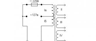
When winding a toroidal coil, only external and interwinding insulation is used. Despite the even laying of the winding wires, the winding thickness along the inner diameter necessarily increases due to the difference between the outer and inner diameters of the core. Therefore, it is recommended to use conductors whose insulation has increased mechanical and electrical strength, for example, PELSHO and PESHO brands, and in some cases - PEV-2. For external and inter-winding insulation, cambric tape, LShSS varnished fabric, 0.06-0.12 mm thick, as well as triacetate or fluoroplastic film, 0.01-0.02 mm thick, are most often used. Formulas for calculating a toroidal transformerThe main parameters for calculating a toroidal transformer are the power supply voltage (Uc) equal to 220 V, the output voltage value (Un) - 24 V, current load (In) - 1.8 A. To determine the power of the secondary winding there is a formula: P = U n x I n = 24 x 1.8 = 43.2 W. Next, the overall power of the transformer device is determined by the formula: The efficiency value and other data necessary for calculations are selected from the table in the appropriate column and row for a specific overall power. The next step is to calculate the cross-sectional area of the core using the formula: The selection of core sizes is carried out as follows: The closest type of core with standard parameters will be OL50/80-40, with a cross-sectional area S = 60 mm2, which should be no less than the design one. The inner diameter of the core is determined in accordance with the condition that dc has a value greater than or equal to dc':
Now you need to determine the number of turns in the primary and secondary windings: Since magnetic flux dissipation in any toroid is very insignificant, the voltage drop in the windings can only be determined by their active resistance. As a result, the relative value of the voltage drop in the windings of a toroidal transformer will be much less than in conventional transformers. In this regard, losses in the resistance of the secondary winding are compensated by increasing the number of turns by approximately 3%. The calculation will look like this: W1-2=133 x 1.03=137 turns. The diameters of the winding wires can be determined by the formula: Here I1 is the primary winding current, determined by its own formula: Transformers manufactured according to calculations using the table have been successfully tested at a constant maximum load operating for several hours. Thus, the calculation of a toroidal transformer allows one to obtain accurate results confirmed in practice. Using this technique, you can determine the necessary parameters for any device. | ||||
| Efficiency | 0,76-0,88 | 0,88-0,92 | 0,92-0,95 | 0,95-0,96 |
3. The actual cross-section of the steel of the magnetic core at the location of the transformer coil;
4. The calculated cross-section of the magnetic core steel at the location of the transformer coil;
5. Actual cross-sectional area of the core window;
6. The value of the rated current of the primary winding;
Table No. 2.
Value Total power of secondary windings Pout, [W]2-15 15-50 50-150 150-300 300-1000
| COS Φ | 0,85-0,90 | 0,90-0,93 | 0,93-0,95 | 0,95-0,93 | 0,93-0,94 |
7. Calculation of the wire cross-section for each of the windings (for I1 and I2);
Table No. 3.
Magnetic circuit design Current density J, [A/mm sq.] at Pout, [W]2-15 15-50 50-150 150-300 300-1000
| Ring | 5-4,5 | 4,5-3,5 | 3,5 | 3,0 |
8. Calculation of the diameter of the wires in each winding without taking into account the thickness of the insulation;
9. Calculation of the number of turns in the transformer windings;
n is the winding number, U' is the voltage drop in the windings, expressed as a percentage of the nominal value, see table.
In toroidal transformers, the relative value of the total voltage drop in the windings is significantly less compared to armored transformers.
Table No. 4.
Tor, value U' Total power of secondary windings Pout, [W]8-25 25-60 60-125 125-250 250-600
| U'1 | 7 | 6 | 5 | 3.5 | 2.5 |
| U'2 | 7 | 6 | 5 | 3.5 | 2.5 |
Table No. 5.
Magnetic circuit design Magnetic induction Vmax, [T] at Pout, [W] 5-15 15-50 50-150 150-300 300-1000
| Thor | 1,7 | 1,7 | 1,7 | 1,65 | 1,6 |
10. Calculation of the number of turns per volt;
11. Formula for calculating the maximum power that the magnetic circuit can deliver;
Sst f – the actual cross-section of the steel of the existing magnetic circuit at the location of the coil;
Sok f – actual window area in the existing magnetic circuit;
Vmax - magnetic induction, see table No. 5;
J - current density, see table No. 3;
Kok - window fill factor, see table No. 6;
Kst is the coefficient of filling of the magnetic circuit with steel, see table No. 7;
What technical advantages do toroidal transformers have?
- Cost-effective performance of a power element with a ring magnetic core. Internally, power transmission occurs with smaller size and weight.
- Compactness and small volumes of the product. That is, winding a toroidal transformer performs its task without failure, but the transformer itself is half the size compared to other models.
- Easy to install and operate. Undoubtedly, transformers with a ring core are very easy to install in the position specified according to the circuit, connect, and test before the first operational start-up. And it doesn’t matter where the installation is planned - inside or outside.
- Saving electrical impulse. About a third of the energy produced is retained both at full load and at idle.
- High thermal load capacity. The shape of the magnetic circuit – a toroid – contributes.
With so many technical advantages, the toroidal transformer wins in many respects. For example, compared to armored and rod transformers, it has low dissipation rates, therefore it is safe and simply indispensable for sensitive electronic equipment.
Functional characteristics of the device
The standard design of the toroidal device is made in the form of a single-phase power transformer with step-down or step-up properties. There are more than two windings in a toroidal core.
The operating principle of such a transformer is no different from rod or armored structures. Its main function is also to convert one electrical voltage value to another. However, the design features of the core make it possible to produce devices with significantly less weight and dimensions. This contributes to the growth of technical and economic characteristics and other indicators of the toroidal transformer.
The shape of the cores is of great importance for this type of electrical machines. Their ring configuration is considered the most optimal, providing significant savings when winding such a transformer. This is due to the fact that the winding is symmetrically and evenly distributed on the surface of the core. Due to this, its length decreases, which leads to a decrease in winding resistance and a simultaneous increase in efficiency.
What are the advantages of a toroidal transformer core?
Recall that the core or magnetic circuit of the toroidal transformer 220 is manufactured in the form of a ring. And this is almost an ideal form in physical terms. For its production, tape-shaped permalloy is most often used in production, and the material consumption is small, and rejection and trimming on the conveyor is reduced. At the second stage of the sequential manufacturing of the transformer, a winding is applied to its core and distributed evenly without flaws over a given surface. The length of the winding wires is short, so the resistance force in the segment is also reduced. And this provides the toroidal transformer with high efficiency. The core of the toroidal transformer itself plays an important role in this.
Definition of Toroidal Transformer Design
For those interested in the issue, we recommend studying the book by S.V. Kotenev, A.N. Evseev on calculating the optimization of toroidal transformers (Hot Line - Telecom publication, 2011). We remind you: the publication is protected by copyright law. Professionals will find the strength (means) to purchase a book if necessary. According to the chapters, the calculation begins by determining the idle speed parameters. It describes in detail how to find active and reactive currents and calculate key parameters.
The printed publication, despite some controversial presentation, simultaneously makes it clear why a transformer connected to the circuit, without a load, does not burn out (the current energy is consumed by magnetization). Although it would seem that the obvious outcome of the event was predicted.
The number of turns of the primary winding is selected from the condition that the magnetic induction does not exceed the maximum value (before entering the saturation mode, where the value does not change with increasing field strength). If the design is carried out for a 230 volt household network, a tolerance is taken in accordance with GOST 13109. In our case, this means an amplitude deviation within 10%. We remember: the entire industry switched to 230 volts in the 21st century (220 is not used, it is cited in the literature as a “legacy of a difficult past”).
What must be taken into account when calculating a toroidal transformer
In order to apply the standard physical formula, you first need to know the parameters of the voltage that will be supplied to the primary winding of the product (symbol for the formula - U), the outer and inner diameter of the core or magnetic circuit (symbol for calculations - D and d), and, The main thing is not to forget about the thickness of the magnetic circuit - H.
An important indicator is the area of the core window (previously recorded in the records - S). The intensity of excess heat removal largely depends on it. These core gap areas range from 80 to 100 cm, and the cross-section is half as large.
Just in case, let us remember the calculation formulas in the article: S0 = * d2 / 4., Sc = H * (D – d)/2.
Universal welding machine with toroidal core
Why “multi-welding”? Because this welding transformer (CT) has many important additional functions. If in a traditional “welder”, which has a magnetic circuit assembled from U- and W-shaped plates, there is sometimes nowhere to squeeze in at least one or two auxiliary turns, then in the proposed donut-shaped design there was plenty of free space.
As a result, he is able to cook with AC/DC, charge batteries, melt metal, power electric burners in Skillful Hands circles with safe voltage, and also do a lot of other things. It’s time to even pose the question differently: what other winding and for what purpose would the user of such a CT additionally want to have?!
Indeed, the core of the “welder”, which has the shape of a “donut”, called a torus in mathematics and technology, has a great future. Understanding this, but not having at their disposal special industrially manufactured toroidal magnetic cores intended exclusively for transformers, home-made manufacturers are forced to adapt cylindrical ersatz from the stators of old electric motors with a power of 1-1.5 kW for their STs. For this purpose, the housings of electric motors are usually simply broken, the windings laid in the grooves are thrown away as unnecessary, the protrusions of the poles are cut out, and all this is only so that a thickness of copper can be wound onto the resulting blanks (rather reminiscent not of donuts, but of excessively heavy, lopsided, bottomless barrels) to achieve “ super goals" - cook steel with "five"!
I am convinced that there is no need to damage electric motors, even if they have become unusable - a zealous owner will always be able to rewind burnt out windings and replace worn-out bearings. A rebuilt engine is capable of much more...
And for the toroidal magnetic circuit I propose, 5 - 6 kg of scrap transformer steel is enough. Moreover, here you can be content with even the same amount of roofing iron (annealed) as the starting material.
The technology for manufacturing a magnetic circuit from such raw materials is quite simple (Fig. 1). All scrap flat transformer steel is cut with scissors into strips of approximately equal width.
Rice. 1. Formation of a toroidal magnetic circuit: 1 - base of the mold; 2 - external cylinder-formwork (“corolla” of the gear for starting the GAZ-53 car with a starter); 3 - internal cylinder-formwork (60 mm section of steel pipe 100×6, slightly machined, wrapped in two or three layers of paper); 4 - initial mass (plates 60-70 mm wide, cut from scrap from W- and U-shaped transformer steel plates, coated with quick-drying office glue, gum arabic or oil paint and laid over the roof, followed by filling the voids with roofing waste)
Practice shows that most often you have to deal with rectangles 60-70 mm wide or slightly smaller analogues, cut from U- and W-shaped plates. All “iron transformer” waste, as well as roofing waste, are also used. After smearing both sides with some quick-drying glue such as stationery (“liquid” glass), gum arabic, or even cheap oil paint, they are tightly laid with a slight overlap in the formwork (as when pouring a hollow concrete column) from available materials.
In the author's technology, the inner cylinder of the formwork (Fig. 1) is a 60 mm section of steel pipe 100×6 mm. Inside, it must be sharpened slightly into a cone and wrapped (to make it easier to later remove from the “cast” magnetic circuit) with two or three layers of paper strip. And as an external one, a removable “rim” of the gear is used (internal diameter is about 250 mm) - from the starter starting system of the GAZ-53 car.
Of course, other suitable workpieces that can withstand the mechanical stresses that arise during the “casting” of the toroidal magnetic circuit can be used for formwork. And they are considerable, especially when you have to hammer small plates into all the slot holes (preferably, they correspond to the width of the set).
Once the glue has dried, the toroidal core can be considered almost ready. True, it still needs to be made of one-sided rounded half-rings - “half-bubble” - from insulating material. At least from plywood - for better installation of future windings and to avoid short circuits to the sharp edges of the magnetic circuit.
This will also be facilitated by preliminary wrapping of the torus with two or three layers of keeper tape, fiberglass or fabric strip impregnated with drying oil.
Now about the windings of the “welder”. Science asserts, and practice clearly proves, that a transformer operates in the most advantageous mode for it if a current equal to 5 A passes through its windings through 1 mm2 of the cross-section of a copper wire. Under extreme conditions, this figure can increase to 13 A, but at This causes the wires to get very hot and burn out.
For welding, even with a 3-mm electrode, a current of at least 80 A is required. This means that the cross-section of the cores of the copper cable or power (welding) bus must correspond to it. Taken with a substantial margin, for a good-quality homemade welding transformer it is usually in the range from 25 to 35 mm2.
Starting from the already mentioned “minimum welding” 80 A and taking into account the widely practiced ratio of turns of the mains and power windings of approximately 5:1, we find: the current of the mains winding must be at least 16 A. It follows that to install the mains winding it is necessary to take a copper wire with a cross-section not less than 3.2 mm2. However, perhaps the best option is PEV2 with a diameter of 2-2.5 mm.
It is generally accepted (and this is confirmed by practice) that with a “cast” magnetic core having a cross-sectional area along the transformer steel equal to 40 cm2, each turn of the winding will correspond to a voltage of 1 V. Taking into account the possible instability of the power supply, the network winding should be made with a reserve.
The reference point is 250 turns. Moreover, after the 190th, it is advisable to provide (without cutting the wires!) taps every ten turns. Of course, the switch for them must be quite reliable, ensuring good electrical contact in order to avoid large energy losses and strong heating during operation of the CT.
Actually, winding a network winding is a rather difficult operation. It has to be done using long wooden shuttles (Fig. 2). Do everything carefully, avoiding overlapping of turns, formation of knots and damage to the layer of insulating varnish on the wire.
Otherwise, you can expect the appearance of interturn short circuits and overheating of the transformer.
Rice. 2. Laying the turns of the network winding of the “welder” (interlayer insulating gaskets are not shown): 1 - toroidal magnetic circuit; 2 - one-sided rounded half-ring - “half-bubble” made of insulating material (2 pcs.); 3 - fastening insulating gasket (2-3 layers of keeper tape, fiberglass or fabric strip impregnated with drying oil); 4 - network winding wire (PEV2, diameter 2-2.5); 5 - wooden shuttle
If you place the core on two supports with a soft coating (lining), which prevents damage to the wire insulation when winding the CT, then the entire work will take about two hours. It is advisable to finish it “in one pass” so that the winding does not weaken and is as dense as possible, with insulating gaskets between the layers.
After the network has been wound, it’s a good idea to check it at idle. If even after a long period of operation the magnetic circuit with the winding becomes only barely warm, then everything is in order. Significant heating is evidence that either there are few turns, or there is an interturn short circuit (or even a breakdown of the winding to the housing!).
Secondary insulation - welding or power - must be laid on the two-three-layer insulation of the network winding. And this is from 40 to 80 turns of a copper bus or multi-core cable. The latter is preferable for the following reasons: welding sleeves can be immediately made from it; winding is significantly easier; the service life of the welding winding increases while simultaneously simplifying the operating conditions, which is especially important when experimenting with such a CT. In addition, connecting the rectifier is simplified and it becomes possible to effectively regulate the welding current and voltage by performing a simple operation - winding or unwinding turns of the cable.
For homemade welding machines that are not too powerful, the following work schedule is desirable: a minute for welding, two for a technological break to cool the welding machine. The use of small fans gives good results. Probably, even more can be achieved by using the simplest heat-emitting radiators to cool the “welder,” as well as mineral oils that can improve the insulation of the CT windings.
A good welding transformer should have a steeply falling characteristic. This can be achieved by dividing the winding into two equal parts. On one side of the core, half of the network and half of the power windings are wound, and on the other - the rest (and in order not to get confused later - in the same sequence).
Apparently, it is worth recalling that a transformer is a reversible device: if you connect the alternating voltage for which it is designed to any winding, then the others appear to be those for which they were intended. By the way, many radio amateurs do the same when determining the windings in an unknown transformer.
Taking into account the above, it is not at all necessary to wind the network (primary) winding of the vehicle first, and then the welding (secondary) winding on top of it. The order of winding, as well as their serial numbers, is only a condition for faster and more familiar orientation in the circuit diagram of the “welder”. Therefore, if, say, you need to wind one of the windings with a fairly rigid busbar, when laying it you will have to resort to a mallet, then, of course, it is more convenient to place such “copper” first on the core, so as not to damage the more pliable and vulnerable wires of the remaining windings.
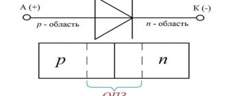
And further. If there is enough wire for one winding, and very little for another winding, then first proceed to the one where your capabilities are limited. Because if there is a clear shortage of cable or busbar for the power (welding) winding, but in the presence of powerful diodes-semiconductor valves, it becomes profitable to abandon welding with alternating current in favor of direct current (Fig.
3). In this case, the voltage from the CT, and therefore the number of turns in the welding winding, is sufficient to be kept to a minimum. If the bus has damaged insulation, then it is recommended to first anneal it with cooling in water (the copper will become soft), insulate it with shellac and fiberglass, and only then begin to wind it onto the magnetic circuit.
Fig 3. Circuit design of a welding rectifier with a current regulator for a homemade multi-welding transformer (R1 - a spiral of nichrome wire with a diameter of 3-5 mm with a movable knife-shaped contact)
Do-it-yourselfers often have difficulties connecting the power cable to the product being welded: either the contact is poor or there is nothing to “grab” to. Two types of devices can help in such situations (Fig. 4): a magnetic contact and an alligator clip. Both homemade products are extremely easy to make, fast and easy to attach.
If there is no proper contact, it is enough to rub them a little on the part.
Rice. 4. Options for devices for ground contact - magnetic (a) and alligator clip (b): 1 - welding cable; 2 - handle; 3 — steel plate; 4 - ring magnet - “stuck”; 5- screw (quantity and location - at the installation site); 6 - half of a homemade “toothed jaw” clothespin (from a piece of steel pipe of a suitable size, 2 pcs.); 7 — steel axle, riveted on both sides; 8 - spring.
It’s also a good idea to equip the CT network winding with a standard AP automatic machine, designed for at least 30 A - with its help it is convenient to turn off the transformer during pauses between welding. This will significantly save electricity, create favorable conditions for timely cooling of the device, and make work safer.
Well, the presence of a powerful rectifier (Fig. 3) will allow, as already noted, to use the resulting unit when charging batteries or organizing multi-station power supply, for example, low-voltage soldering irons and electric burners in “Skillful Hands” school clubs. Moreover, such a unit is truly indispensable, for example, when performing galvanic work at home or starting a car in cold conditions.
It is very interesting and promising to equip the CT with an additional winding containing only one full turn of an annealed copper busbar 5x50 mm or a thick stranded copper cable with a diameter of about 20 mm (with ends made of sections of thick-walled copper pipe). As practice has shown, with the help of such a winding it is possible to perform hot open forging, hardening and bluing, soldering and surfacing; bending of metal strip, pipe, thick steel rod, round timber, brittle wire; casting of tin, zinc, lead; unscrewing “stuck” bolts, studs and nuts; spot welding, hot fit and a number of other operations.
How to smoothly regulate the current? Yes, at least in the way mentioned above - by adjusting the power (cable) winding. When winding part of it from the magnetic circuit, the voltage decreases with a simultaneous increase in the current from the CT, but, in particular, the conditions for ignition of the arc worsen.
And vice versa: rewinding the cable leads to an increase in the transformed voltage with a simultaneous decrease in the current supplied to the load. In this case, the electric arc ignites better.
Or another option, when the welding cable is connected to the product not directly, but through several turns of wire with high resistance (for example, nichrome). How many resistant turns are there are so many stages of welding current adjustment. The arc is ignited in almost the same way in all cases.
The CT current can be adjusted using a combined valve made of transformer steel and non-ferrous metal. In this case, a cross cut is made on the magnetic core.
Plumbers, motorists, repairmen and just those who like to do things with their own hands, this “welder” with such universal properties is for you.
R. KRAVTSOV, Yeisk, Krasnodar region. Modeler-constructor 2004 No. 2.
Is it possible to make a toroidal core yourself?
A geometrically correct toroidal core is not so easy to reproduce independently, especially by novice inventors. Firstly, you need to have at your disposal a special permalloy tape, also sometimes called transformer steel. Secondly, familiarize yourself with the rules for forming a torus of rectangular cross-section. The actions are familiar - you need to roll the material into a roll. Actions are consistent and careful, if necessary, go back a step.
A special wooden shuttle with technical semicircular cutouts can be a help in this matter, especially if you need to calculate how much material is needed for winding. The wire for the winding is always taken with an allowance. Recommended reserve is 20-30%.
Thus, it becomes clear that a toroidal transformer can give a head start to other existing power elements. And all because it is simple, reliable and functional. The existing core is created in an advantageous form, which is easy to work with not only at the stage of product manufacture, but also during installation, operation and repair. It is possible to make such a transformer yourself, but this will require perseverance, knowledge, the desire to create a product, the desire to make calculations and look for alternatives.
Selection and production of a toroidal core
The best material for the manufacture of a toroidal magnetic core is transformer strip steel. To make the core, this tape is rolled into a roll shaped like a torus of rectangular cross-section. If there is such a tape or a core made from it, then there will be no special problems in the manufacture of a magnetic core for a toroidal transformer.
Characteristics of welding transformers.
If the internal diameter d is small, you can unwind part of the tape from the inside of the torus, and then wind it on the outer surface of the core. As a result, both diameters will increase, and the area of the internal part of the magnetic circuit will increase. True, the cross-sectional area of the core S0 will decrease somewhat. If necessary, you can add tape from another magnetic circuit.
A good ready-made toroidal core can be taken from a laboratory autotransformer LATR 1M designed for a current of 9 A. You just need to rewind its windings. It happens that the stator magnetic circuit of a suitable electric motor is used to make a toroidal core for a transformer.
Another way to manufacture a toroidal core is to use plates from a faulty powerful industrial or power transformer, which at one time powered a tube color TV, as a material. First, a hoop with a diameter of about 26 cm is made from these plates using rivets. Then, inside this hoop, they begin to insert the plates end-to-end, one after another, holding them with your hand from unwinding.
After setting the required cross-section S0, the magnetic circuit is ready. To increase S0, two toroids of the same size can be made and then joined together. The edges of the toroids should be slightly rounded using a file. Two rings should be made from electrical insulating cardboard, having an internal diameter d and an external diameter D, as well as two strips on the inner and outer sides of the torus. After placing them on the toroid, the core is wrapped over the cardboard spacers with keeper or woven insulating tape. The magnetic core is ready, and you can start winding the windings.