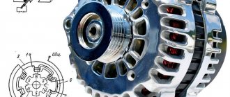
How the device works
To convert one voltage level to another, pulse voltage converters using inductive energy storage devices are often used. According to this, three types of converter circuits are known:
- Inverting.
- Raising.
- Downgrades.
These types of converters have five elements in common:
- Key switching element.
- Power supply.
- Inductive energy storage (choke, inductor).
- A filter capacitor that is connected in parallel with the load resistance.
- Blocking diode.
The inclusion of these five elements in different combinations makes it possible to create any of the listed types of pulse converters.
Circuit of a simple voltage inverter.
Regulation of the output voltage level of the converter is ensured by changing the width of the pulses, which control the operation of the key switching element. Stabilization of the output voltage is created by the feedback method: a change in the output voltage creates an automatic change in the pulse width.
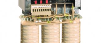
A typical representative of a voltage converter is also a transformer. It converts AC voltage of one value to AC voltage of another value. This property of a transformer is widely used in radio electronics and electrical engineering.
Table - Main characteristics of the voltage converter.
Material on the topic: What is called a trigger in electronics.
Linear and pulse converters
When considering the features of the use of converters, it will be useful to pay attention to the classification by which they are divided into linear and pulsed. In fact, these criteria reflect the two most important principles of operation of converters
Those that are linear can operate on the principle of analog circuitry, in which the converted signals are generated at a smooth pace. A pulse converter involves a more active representation of signals both at the output and during their internal processing. However, if this operation is carried out only at the internal stage of signal processing, the corresponding device can generate virtually the same indicators as in the case when a linear converter is used. Thus, the concept of linear or pulse processing can only be considered in the context of the principle of operation of the key hardware components of a device of the corresponding type.
Pulse converters are mainly used in cases where the infrastructure used involves processing high-power signals. This is due to the fact that the efficiency of the corresponding devices in such cases is much higher than when they are used to process signals of lower power. Another factor in choosing these solutions is the use of transformer or capacitor devices as part of the infrastructure used, with which pulse converters have optimal compatibility.
In turn, a linear converter is a device that is used within the framework of an infrastructure in which low-power signals are processed. Or if there is a need to reduce interference generated by the operation of the converter. It is worth noting that the efficiency of the solutions under consideration in high-power infrastructure is not the most outstanding, therefore these devices most often emit a larger amount of heat than switching converters. In addition, their weight and dimensions are also significantly larger.
But, one way or another, in practice, the operation of a converter according to the pulse principle may imply the formation of its transfer function in linear form. Therefore, before introducing the corresponding signal converters into the infrastructure, their internal structure should be examined in relation to the applied signal processing circuitry.
What is a voltage converter
A converter is an electrical device that converts electricity with certain parameters or quality indicators into electricity with other values of parameters or quality indicators. The parameters of electrical energy can be the type of current and voltage, their frequency, number of phases, and voltage phase. According to the degree of controllability, electrical energy converters are divided into uncontrolled and controlled. In controlled converters, the output variables: voltage, current, frequency can be adjusted.
According to the element base, electricity converters are divided into electric machine (rotating) and semiconductor (static). Electric machine converters are implemented based on the use of electrical machines and currently find relatively rare application in electric drives. Semiconductor converters can be diode, thyristor and transistor.
Based on the nature of electricity conversion, power converters are divided into rectifiers, inverters, frequency converters, AC and DC voltage regulators, and AC voltage phase number converters.
Modern automated electric drives mainly use semiconductor thyristor and transistor converters of direct and alternating current. The advantages of semiconductor converters are broad functionality for controlling the process of converting electricity, high speed and efficiency, long service life, convenience and ease of maintenance during operation, ample opportunities for implementing protection, alarms, diagnostics and testing of both the electric drive itself and technological equipment.
Operating principle of a voltage converter.
At the same time, semiconductor converters also have certain disadvantages. These include: high sensitivity of semiconductor devices to overloads of current, voltage and the rate of their change, low noise immunity, distortion of the sinusoidal shape of current and network voltage.
How are capacitors indicated in the diagram?
Read more
What is the difference between parallel and series connection of resistors?
Read more
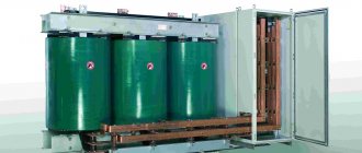
Oil transformers - what they are, device and principle of operation.
Read more
Classification
By the nature of the transformation
| Converters | |||
| Rectifiers≈ → = | Inverters= → ≈ | Frequency and phase converters≈ → ≈ | Voltage= → = inverter + rectifier≈ → ≈ Transformer |
Rectifiers
Main article: Rectifier
A rectifier is a device designed to convert the energy of an alternating current source into direct current.
Inverters
Main article: Inverter (electrical engineering)
Inverter
- a device whose task is the opposite of a rectifier, that is, converting the energy of a direct current source into alternating current energy.
Inverters are divided into two classes: grid driven
(dependent) and
autonomous
.
Dependent inverters
Slave inverters
convert the energy of a direct current source into alternating current and release it into the alternating current network, that is, they carry out the conversion inverse to the rectifier.
Autonomous inverters
Autonomous inverters
- devices that convert direct current into alternating current with a constant or adjustable frequency and operate on an autonomous (not connected to the alternating current network) load.
In turn, autonomous inverters are divided into:
- AIN
- AIT
- AIR
Frequency converters
Main article: Frequency converter
Frequency converter
- a secondary power source that produces alternating electric current with a frequency different from the frequency of the current source.
Voltage converters
- power supplies: uninterruptible power supplies
- Pulse (DC)
- Phase (AC)
- Managed
- Uncontrollable
Features of application
At the moment, such equipment is used in almost all industries and every day it is increasingly used in the life of every person, in particular as part of the equipment of cars or trucks. The operating frequency of voltage inverters (voltage converters) does not exceed one hundred kilohertz. Plus, a voltage converter (voltage inverter) can be used as a generator. In principle, a generator and an inverter are quite similar, but you should not assume that these types of equipment are the same in purpose and operating principle.
Boost converter.
There are significant differences in the generator and voltage converter circuits. In addition, compared to a diesel or gasoline generator, a voltage inverter (voltage converter) has a number of advantages, in particular:
- the voltage inverter (voltage converter) has significantly smaller dimensions and weight;
- The voltage inverter (voltage converter) does not need to constantly monitor a whole list of parameters that are mandatory when operating diesel power plants or gasoline generators. These parameters include fuel level, engine oil level and pressure, coolant temperature and level. All these parameters, for example, when operating a voltage inverter (voltage converter) from a car engine are controlled independently, in addition, with relatively low-power consumers (say, up to 1000 W), turning on the car generator for a long time is not required at all and, naturally, no fuel is consumed;
- at idle, the voltage inverter (voltage converter) has a meager energy consumption (about 5 W), in contrast to a diesel or gasoline generator, which at idle consumes up to fifty percent of the consumption at maximum load;
- absence of mechanical wear, respectively, better fault tolerance and longer service life;
- the fluctuation in the output frequency of the voltage inverter (voltage converter) is minimal and, as a rule, does not exceed hundredths of a percent;
- the voltage inverter (voltage converter) is environmentally friendly (does not make noise and does not emit exhaust gases) and allows you to connect alternative energy sources (for example, solar panels or wind generators);
- a voltage inverter (voltage converter) can be used as a starter-charger, as an uninterruptible power supply, as a battery restorer;
- and, finally, a voltage inverter (voltage converter) is simply significantly (up to several times!) cheaper.
Table - Popular models of voltage converters.
The list of potential users of voltage inverters (voltage converters) can be very wide. Here are producers of various works in remote conditions or with frequent power outages, and lovers of outdoor recreation who want to preserve the opportunity to enjoy the “benefits of civilization”, and prudent owners of various industries or protected objects, etc. and so on.
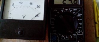
Material on the topic: Principles of operation of a multimeter and features of choice.
In particular, the use of voltage inverters (voltage converters) in conjunction with various autonomous power sources provides very big advantages; the fuel savings alone are worth it, and there is also a stored “reserve of electricity”, so to speak, just in case.
It will be interesting➡ Why do you need a frequency converter
True, when choosing voltage inverters (voltage converters), it is necessary to remember that many consumers of electric current (especially refrigerators and pumps) have a starting power several times higher than the rated power (usually, you can look at the device’s passport) and it is this that should be taken as a basis when calculating the required voltage inverter (voltage converter).
Converter 24V to 12V
Application of multi-level inverters [ edit | edit code ]
Multilevel inverters include an array of power semiconductors and capacitor voltage sources, the output of which generates voltages with stepped waveforms. Switch commutation allows capacitor voltages to be added that reach high output voltages, while power semiconductors only have to withstand reduced voltages. The figure on the right shows a schematic diagram of one phase segment of inverters with a different number of levels for which the power of semiconductors is represented, represented by an ideal switch with several positions.
A two-level inverter generates an output voltage of two values (levels) relative to the negative terminal of the capacitor, while a three-level inverter generates three voltages, and so on.
Let's imagine that m
is the number of phase voltage steps relative to the negative terminal of the inverter, then the number of steps in voltage between two load phases
k
,
k = 2 m + 1
and number of steps p
in phase voltage of three-phase load in connection
p = 2 k − 1
There are three different topologies for multi-level inverters: diode clamped (neutral clamped); fixed to the capacitor (mounted capacitors); and cascaded multi-element with separate DC supplies. In addition, several modulation and control strategies have been developed or adopted for multi-level inverters including the following: multi-level sinusoidal pulse width modulation (PWM), multi-level selective harmonic cancellation, and space vector modulation (SVM).
The main positive aspects of multi-level inverters are as follows:
1) They can generate output voltages with extremely low distortion and lower dv/dt.
2) They draw input current with very low distortion.
3) They generate less common mode (CM) voltage, thus reducing stress in motor bearings. Moreover, by using sophisticated modulation techniques, CM voltages can be eliminated.
4) They can operate with lower switching frequency.
Topology of cascaded multilevel inverters
The various inverter topologies presented here are based on the series connection of single-phase inverters with separate DC sources. The figure on the right shows the power supply circuit for one phase section of a nine-level inverter with four cells in each phase. The resulting phase voltage is synthesized by adding the voltages generated by the different sections.
Each single-phase full bridge inverter generates three terminal voltages: + Vdc, 0, and – Vdc. This is made possible by connecting capacitors in series with the ac side through four power switches. The resulting output AC voltage swing is -4 Vdc to 4 Vdc with nine levels and a stepped waveform, almost sine wave, even without the use of filters.
To convert electricity, or more precisely, voltage, you can use various devices, such as transformers, generators, chargers. All of them are electrical energy converters. Since many modern devices require not only alternating but also direct voltage to power them, it is not always possible to use an energy source such as a rechargeable battery for these purposes. It is she who produces the ideal constant voltage through a chemical reaction. Previously, only low-frequency transformers, paired with a rectifier and a smoothing filter, were used to convert and reduce voltage. However, they were very large in size. With the growth and development of innovative technologies in everyday life and in production, electronic devices began to appear that require miniature converting devices. This is how pulsed DC voltage converters appeared. Their miniature size is required more for portable mobile devices than for stationary ones.
All pulse converters can be divided into the following groups:
- Boost, buck, invert;
- With and without stabilization;
- With and without galvanic isolation;
- Regulated and unregulated;
- Having different ranges of input and output voltage.
However, pulse converters are assembled using more complex circuits than their predecessors, classic step-down rectifiers.
Types of converters
When choosing a converter model, you must also take into account the characteristics of electricity consumption by various devices; taking into account the characteristics of consumption, electrical appliances can be divided into 2 groups.
The first group is electrical appliances, when turned on and at the beginning of operation, the short-term power consumption (the so-called peak starting load) is several times higher than the rated power. This group includes, for example, pumps, compressors and refrigerators; to connect them, you often have to use isolation transformers.
Expert commentary
Lagutin Vitaly Sergeevich
Engineer with a degree in Computer Software and Automated Systems, MEPhI, 2005–2010.
Ask a Question
The real power of some devices, for example, pumps based on asynchronous motors and equipment based on them (air conditioners, refrigerators), is approximately 1.5 times greater than the rated power, this is due to the fact that the power is usually indicated without taking into account losses (net power). For devices in this group, it is necessary to select a voltage converter with a maximum permissible power that significantly exceeds the rated power of the device.
The second group is electrical appliances whose starting power does not exceed the rated power, these include televisions, computers, lamps, heaters that consume constant power, as well as tools with commutator-type engines (drills, cutting machines, planes, concrete mixers, lawn mowers, etc.). which consume rated power only when a load is applied, for devices in this group it is enough to select a voltage converter with a maximum permissible power slightly exceeding the rated power of the device.
Electronic voltage converter.
Pulse devices
Pulse converters are used in cases where it is necessary to convert one voltage level to another. Most often they are assembled on the basis of inductive or capacitive energy storage devices. They are distinguished from other power sources by their high level of efficiency, reaching 95% in some cases. Schematic electrical circuits of pulse converters are made using 4 elements:
- switching element;
- energy storage (inductor, inductor, capacitors);
- blocking diode;
- a capacitor connected in parallel with a load resistance.
Combinations of the listed components can form any type of pulse converter. The output voltage is determined by the width of the pulses that control the switching element. This creates a reserve of energy in the inductor. Stabilization is realized through feedback, that is, the pulse width changes depending on the value of the output voltage.
Switching voltage converter.
To create high-frequency currents, converters assembled using oscillatory circuits are used. In this case, the direct current voltage supplied to the alternating voltage generator (multivibrator, trigger) is also the supply voltage. The output pulses are usually rectangular in shape. The resulting alternating voltage can be increased, decreased, etc.
In addition, it is easy to straighten and obtain the desired polarity. To do this, use the appropriate connection of diodes, and the rectifier is assembled, for example, using a bridge circuit. The voltage at the output of pulse converters must be stabilized. For this purpose, various types of stabilizers are used (pulse or linear). True, due to low efficiency, the latter are rarely used.
As for pulse stabilizers, they use pulse width or frequency pulse modulation in their work. In the first case, the duration changes; in the second, the frequency of the pulses changes. There are devices with a combined stabilization method.
Car models
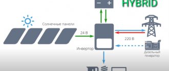
With the increase in the number of cars, the need to use various household appliances during their operation, including those operating on 220V alternating voltage, has increased. For this purpose, automobile inverters were developed, with the help of which the constant voltage from a car battery +12 V (cars) or +24 V (trucks) is converted into alternating 220 V. You can connect an electric razor or electric drill to them, charge a laptop, etc.
A car inverter is a voltage generator whose shape is close to a sinusoid. In this case, the current at the output of the device does not depend on the value of the current at the input and it can be adjusted practically from zero to maximum. In the same way, it is theoretically possible to adjust the frequency and voltage. In a simplified way, the electrical circuit of a car converter can be represented as a transformer, the primary windings of which are supplied with voltage through thyristor switches. Alternately turning on the windings, the thyristors create alternating current at the output of the transformer.
Automotive voltage converters
In this case, a modified (stepped) sinusoid is formed, but this does not in any way affect the performance of most household appliances. Converters for use in cars have a fairly high efficiency, which reaches 90%, which indicates a fairly high quality of the resulting sinusoid. During the operation of the device, the consumer has the opportunity to choose one of three operating modes:
- An operating mode that ensures long-term operation of the inverter at rated power.
- Overload mode, which allows you to get significantly more power from the device than when operating in normal mode. However, in this mode the inverter should not operate for more than 30 minutes.
- The starting mode is used when it is necessary to obtain instant power under high load (starting an electric motor, etc.).
It will be interesting➡ How to choose a digital-to-analog converter (DAC)
When operating the inverter, it is not recommended to constantly turn it on at maximum power. It is necessary to select its operating mode based on the load size. When choosing a converter for a car, the main attention should be paid to its power. Its value must obviously be greater than the power of the connected devices. In addition, the type of electrical appliances connected is also important. If you plan to connect devices that consume significant currents when starting up to a car inverter, then you need to purchase a device with the appropriate power (from 300 to 2000 W).
Appliances
Currently, voltage converters are widely used in everyday life. They began to be used at home as backup or emergency power sources, the task of which is to ensure the operation of household appliances in the event of an unauthorized shutdown of the centralized power supply network. Typically, a home voltage converter is a combination of an inverter with one or more batteries. In cottages and country houses (dachas), they are also supplemented with devices capable of charging batteries.
Circuit diagram of a household voltage converter.
In some cases, solar panels or wind generators can be used for this. Low-power household appliances are most often connected to inverters intended for home use:
- TVs;
- computers, etc.
In this case, it is necessary to remember about electrical appliances, for example, refrigerators, electric pumps, etc., which require a “pure sine wave” power supply to operate, which requires the purchase of much more expensive devices. In places where there is no centralized power grid, it is possible, by calculating the required electrical power, to organize a power supply system for the whole house. However, this will require the purchase of fairly expensive equipment.
Household voltage inverter.
For example, the cost of an inverter with a capacity of 10...60 kW is at least $20,000. The use of this kind of devices is advisable in the case of organizing power supply systems based on alternative energy sources. If we compare a classic uninterruptible power supply (UPS) operating online with voltage conversion, then the combination of “battery + inverter” components looks preferable for a number of reasons, including:
- gentle operation of batteries;
- large selection of batteries;
- possibility of parallel connection of several converters, etc.
On the domestic electrical equipment market, pulse converters are presented in a fairly wide range. The products of these manufacturers are of high quality and have a large number of different functions. Thus, DC/AC converters provide protection for deep discharge of batteries by controlling the minimum input voltage. They also control the parameters of the output signal.
Additional material on the topic: How to check the battery using one multimeter.
Transformerless devices
Features of a voltage converter from 12 V to 220 V. Recently, they have become very popular, since their production, and in particular the production of transformers, requires a lot of money, because their winding is made of non-ferrous metal, the price of which is constantly growing. The main advantage of such converters is, of course, the price. Among the negative aspects, there is one thing that significantly distinguishes it from transformer power supplies and converters. As a result of a breakdown of one or more semiconductor devices, all the output energy can reach the terminals of the consumer, and this will certainly damage it.
Here is the simplest AC to DC voltage converter. The role of the regulating element is played by the thyristor. The situation is simpler with converters that do not have transformers, but operate on the basis and in the mode of a voltage-increasing device. Here, even if one or several elements fail, dangerous destructive energy will not appear on the load.
Transformerless voltage converters.
The most common schemes
There are several classic standard circuits that are most often used in pulsed-DC converters. They provide different ratios between input and output voltage. These diagrams reveal the very essence of converters and their operating principle.
Step-down voltage converter and its circuit
It is used to power consumers whose load is expressed by high currents and low voltage. This is a first-priority circuit that can replace a classic low-frequency converter, in turn, will increase efficiency and reduce the size and weight of the device. The VT transistor acts as an electronic switch; its operation lies between the two modes of misfire (complete closing) and saturation (full opening). Each detail is calculated directly for a specific consumer and voltage source. The main disadvantage of this circuit is the likelihood of breakdown and the appearance of a full large input voltage at the consumer. This will undoubtedly cause the powered device to malfunction.
Boost converter and circuit
It can be used to obtain voltage at a consumer or load greater than the energy sources. It is used for backlighting laptop computer displays and for other electronic devices where it is necessary to make more out of a small voltage. Here the process of appearance of self-induction EMF takes place, which appears after the transistor opens. All accumulated energy in the throttle goes to the load. In this case, the voltage at the inductor terminals changes its polarity.
Inverting circuit
Can be used to produce voltage that has reverse polarity. In this case, the value of U out can be less or greater than U in. The energy that accumulates in the inductor is directed to the load through a smoothing capacitor.
As can be seen from these circuits, they all do not have galvanic isolation, that is, direct isolation of the secondary output voltage from the input.
Here is one such circuit containing a transformer. The energy that accumulates in the magnetic field of the primary winding of the transformer is transferred to the load through the secondary winding. The transformer in this case can be both step-up and step-down. It is used very often in network sources where there is a need to reduce the input voltage from several hundred volts to units or tens.
At the moment when the transistor turns off, the transformer’s inductance can cause a high-voltage jump or surge on the collector, which is undoubtedly very bad and can lead to breakdown of the semiconductor element. For this purpose, an RC chain is installed from a capacitor and an inductor, which can be connected in parallel to the switch or the primary winding. Such a flyback pulse converter is widely used in many network sources of electric current with low power of the order of 100 W.
Another circuit with a transformer and direct connection of a diode is shown in the diagram below.
Used in power supplies of about 250 W. All of these converters discussed above are called single-cycle, because during one conversion period only one pulse will be sent to the load. Their main advantage is the simplicity of the circuit, consisting of just one transistor operating in switch mode, and the disadvantage is the magnetization of the core, which prevents the full use of this magnetic material with maximum efficiency. The transfer of energy to the consumer and the preparation of the transformer for the next demagnetization cycle is carried out with a certain pause, which reduces their output power.
Here are several practical circuits implemented in life, the basis of which is a pulse converter. The first of them has a control element made on a microcircuit, in turn, both circuits are made on field-effect transistors. They are calculated for voltage for loads from 5 to 12 Volts.
Operating principle
The voltage converter generates the supply voltage of the required value from another supply voltage, for example, to power certain equipment from a battery. One of the main requirements for the converter is to ensure maximum efficiency. Conversion of alternating voltage can be easily accomplished using a transformer, as a result of which such direct voltage converters are often created on the basis of an intermediate conversion of direct voltage to alternating voltage.
- A powerful alternating voltage generator, which is powered by an original direct voltage source, is connected to the primary winding of the transformer.
- An alternating voltage of the required magnitude is removed from the secondary winding, which is then rectified.
- If necessary, the constant output voltage of the rectifier is stabilized using a stabilizer, which is switched on at the output of the rectifier, or by controlling the parameters of the alternating voltage generated by the generator.
- To achieve high efficiency, voltage converters use generators that operate in switching mode and generate voltage using logic circuits.
- The output transistors of the generator, which switch the voltage on the primary winding, go from a closed state (no current flows through the transistor) to a saturation state, where the voltage across the transistor drops.
- In voltage converters of high-voltage power supplies, in most cases, self-inductive emf is used, which is created at the inductance in cases of sudden interruption of the current. A transistor acts as a current interrupter, and the primary winding of the step-up transformer acts as an inductance. The output voltage is created on the secondary winding and rectified. Such circuits are capable of generating voltages up to several tens of kV. They are often used to power cathode ray tubes, picture tubes, and so on. This ensures efficiency above 80%.
Schematic diagram of a transformerless voltage converter.
Why does world practice need different voltages?
Electrification has been carried out on a massive scale since the beginning of the 20th century. A large number of people took part, each pursuing, in addition to objective, their own interests. Edison promoted constant voltage, Tesla, out of spite, promoted variable voltage. Dolivo-Dobrovolsky had reason to dislike the second scientist (a conflict of interest in the field of three-phase networks); perhaps he introduced the 50 Hz frequency in defiance of the United States; Europe listened to the opinion of an engineer closer to that vicinity.
As for the USSR, there is no doubt: the 220 volt voltage was left only for military and strategic reasons of confrontation in the Cold War. The diameter of the cigarette corresponded to the caliber of the cartridge for the fastest transfer of equipment to the production of specific products.
Device repair
Repair of these devices to convert one type of voltage to another is best done in service centers, where the personnel are highly qualified and will subsequently provide guarantees for the work performed. Most often, any modern high-quality converters consist of several hundred electronic parts, and if there are no obvious burnt elements, then it will be very difficult to find a breakdown and fix it.
It will be interesting➡ How to choose a digital-to-analog converter (DAC)
Some Chinese inexpensive devices of this type, in general, are in principle deprived of the possibility of repairing them, which cannot be said about domestic manufacturers. Yes, they may be a little bulky and not compact, but they can be repaired, since many of their parts can be replaced with similar ones.
What is the purpose of signal converters?
Signal converters are devices that can truly be presented in the widest range of solutions. This term is actually collective and can refer to equipment used in different segments of the economy and classified according to completely different criteria. The main types of signals that the devices in question can convert are:
— electric;
— sound;
— temperature;
- technological nature.
Depending on the tasks facing the user of the signal converter, the structure of the corresponding device can combine modules that process several different types of data. Conversion, therefore, can be carried out within one type of signal (for example, from one frequency to another) or be a mechanism that involves translation between different categories of signals. For example, electrical to sound.
The most common devices include a converter of analog signals to digital (and vice versa, if this is provided for by the structure of the internal modules of the device). Let's consider the features of its work.
A simple homemade voltage inverter 12-220V on two transistors
As a transformer I used ferrite cups with the following dimensions: diameter - 35 mm, height - 20 mm. First, the primary winding is wound; it contains 14 turns of wire with a diameter of 0.5 mm; after winding, it must be wrapped in one layer of electrical tape. The secondary winding of the transformer is wound with a wire with a diameter of 0.2 mm and contains 220 turns; we also wrap it with electrical tape in one layer on top. That's it, the transformer is ready, all that remains is to assemble the halves and place them on the bolt.
Using trial and error, I selected transistors for the circuit, focusing on the minimum current consumption of the circuit. The result was a pair of KT814 and KT940, then the resistance and capacitance were selected. As a result of my experiments, I got the following circuit with the indicated denominations, it is shown above. This design of a simple voltage inverter is perfect for powering an energy-saving lamp with a power of 8,9,11 watts. Lamps with a power of 20 watts do not want to work, most likely the secondary is rather weak - I did not redo it. The 9-watt lamp shines as brightly as when powered directly from the 220V AC mains. The current consumption of the voltage converter circuit ranges from 0.5 – 0.54 Amperes.
Interesting read: How to easily check your computer's power supply for faults.
If you use the KT817 transistor and similar ones instead of the KT940 transistor, then the current consumed by the voltage inverter circuit and the lamp increases to 0.86 Ampere. This design of a simple voltage inverter is available for production by all radio amateurs and beginners. The advantages of this design are obvious: ease of manufacture and reliability in operation.
It should be noted that many radio amateurs live in rural areas and do not have the opportunity to purchase imported parts; moreover, although they are inexpensive, the same field-effect transistors cost money, which can immediately burn out or fail if there is an error, not to mention microcircuits. And most often, a radio amateur has limited supplies of radio components. This is how a simple voltage inverter appeared, assembled from parts obtained from Soviet trash. Having a battery with a capacity of 7 Ampere-Hours, it is not difficult to calculate how long it will last - I checked it personally.
Homemade voltage converter.
FAQ
How does the recommended charging current of up to 0.3C affect the battery plates?
For a conventional lead-acid battery, at charge currents of 0.25-0.3 C, an accelerated hydrogen evolution reaction will occur, which will lead to drying and swelling of the battery. In Carbon series batteries, as a result of the capacitive effect and an increase in the number of plates, large currents will be evenly distributed across the plates, which will prevent negative reactions due to the splitting of water in the electrolyte.
Why doesn't the voltage converter work?
Voltage converter malfunctions often occur due to the use of inappropriate wires (for example, aluminum instead of copper). Many inverter models are power sensitive. They are designed to operate only from rechargeable batteries or stabilized power sources. Such devices cannot be connected to solar panels or gas generators.
What difficulties may arise when repairing a voltage converter?
The main difficulty lies in choosing analogs of transistors and transformers in the absence of original components. The remaining elements of the electrical circuit - for example, resistors, capacitors or diodes - do not have design features, so you can use any available parts that are suitable in voltage, power and rating.
Converter with master oscillator-multivibrator
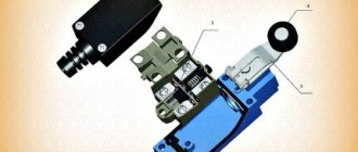
To obtain an output voltage of 30...80 V, P. Belyatsky used a converter with a master oscillator based on an asymmetrical multivibrator with an output stage loaded on an inductive energy storage device - inductor (choke) L1 (Fig. 7).
Rice. 7. Circuit of a voltage converter with a master oscillator based on an asymmetrical multivibrator.
The device is operational in the supply voltage range of 1.0. ..1.5 V and has an efficiency of up to 75%. In the circuit, you can use a standard inductor DM-0.4-125 or another with an inductance of 120...200 μH.
An embodiment of the output stage of the voltage converter is shown in Fig. 8. When a 7777-level (5 V) rectangular control signal cascade is applied to the input of the cascade, the output of the converter, when powered from a 12 V source, produces a voltage of 250 V at a load current of 3...5 mA (load resistance is about 100 kOhm). Inductance of inductor L1 is 1 mH.
As VT1, you can use a domestic transistor, for example, KT604, KT605, KT704B, KT940A(B), KT969A, etc.
Rice. 8. Option for the output stage of the voltage converter.
Rice. 9. Diagram of the output stage of the voltage converter.
A similar circuit of the output stage (Fig. 9) made it possible, when powered from a voltage source of 28V and a current consumption of 60 mA, to obtain an output voltage of 250 V at a load current of 5 mA. The inductance of the inductor is 600 μH. The frequency of control pulses is 1 kHz.
Depending on the quality of the inductor, the output voltage can be 150...450 V with a power of about 1 W and an efficiency of up to 75%.
Phases of operation of a buck converter
Coefficient D affects the duration of opening or closing the key:
Phase 1 – pumping. When the switch transistor is open, the current from the battery, accumulator or other source flows in the direction from the inductor L to the load Rн and the charging capacitor Cout. At the same time, the capacitor and inductor accumulate electricity. The current iL increases smoothly under the influence of the inductance of the inductor. This stage is called pumping. When the load voltage reaches a fixed value, the transistor VT is switched off and the discharge stage starts.- Phase 2 – discharge. The VT transistor is closed, and the inductor does not accumulate energy, because source is disabled. A change in the value and direction of the current flowing through the inductor winding is prevented by inductance L (self-induction effect). As a result, the flow of current does not stop in an instant, and it shorts along the “diode-load” line. For this reason, a VD diode is called a discharge diode. Typically, a high-speed Schottky diode is used for these purposes. At the end of the 2nd phase, the process is repeated cyclically.
The limit value of Uout in this circuit is equal to Uin and cannot exceed it. To obtain Uout˃ Uin, boost converters are used.
2Example of connecting a logic level converter
Let's look at a practical example of how a level converter works.
To do this, let's connect to some 3-volt sensor, for example, temperature and humidity sensor HTU21D . This sensor is controlled via an I2C interface and requires a 3V control signal. At the same time, the Arduino generates a 5V signal. This is where a logic level converter comes to our aid. Let's connect the devices according to this scheme:
Connection diagram of the HTU21D sensor to Arduino via a logic level converter
In order to use the sensor, download the HTU21D library (it is also attached at the bottom of the article). Let's install the library as usual. Let's download the example SparkFun_HTU21D_Demo (File Examples SparkFun HTU21D humidity and temperature sensor breakout). The port monitor will display the measured temperature and humidity values. In real life it looks like this:
Working with the HTU21D sensor via Arduino and converter
Will the HTU21D sensor burn out if connected directly to the Arduino without a level converter? Hardly. But it will operate at higher voltage, which will shorten its service life indefinitely. In addition, the sensor may heat up, which means it will distort the readings of both temperature and humidity. “Glitches” in management are also possible. Therefore, it is better to connect the HTU21D sensor to Arduino via a level converter. As a last resort, if it is not there, you can connect the SDA and SCL lines of the sensor through limiting resistors with a resistance of ~330 Ohms.
The following article describes how to work with the HTU21D sensor in more detail.
Design
To change the level of the current supply voltage, specialized pulse converters with inductive circuits built into them are most often used. In accordance with the task facing them, all known models of converter devices are divided into the following classes:
- Inverting circuits;
- Boosting electronic units;
- Buck converters.
Regardless of the type of these devices, they all work on the same principle, providing the required functionality and quality of the generated signals. The similarity of devices of this class is most often revealed by the following characteristic features:
- Availability of its own power module;
- The switching elements included in the circuit are represented by powerful semiconductor transistors;
- Energy storage devices in the form of a separate choke or coil;
- Filter capacitors connected in parallel with the load resistance;
- Special diodes used as a blocking element.
Switching blocks
The use of all the elements listed above in the required combinations makes it possible to obtain any of the known categories of pulse devices.
Advantages and disadvantages of converter devices
Surge protection device
The advantages of most well-known models of converting devices include:
- High efficiency of converting standard network voltages into a user-friendly form with simultaneous control of their main parameters;
- Compactness and mobility of individual samples of inverter devices, allowing their use as automotive converters;
- Good efficiency indicators with efficiency approaching 90%;
- Versatility and reliability of converter devices, providing the ability to connect any types of consumers;
- Possibility of compensating for electricity losses by increasing the output voltage.
Important! The listed advantages of converting devices allow them to be installed in the most critical components of security and lighting systems, as well as in control modules for the operation of heating boilers, pumping stations and other special equipment.
The advantages of these devices also include the presence of such additional options as the ability to switch indicators of measured quantities from input to output voltage. Let's add to this the admissibility of adjustment within certain limits of controlled output parameters.
Quite removable disadvantages of converters of this class include sensitivity to operation in conditions of high humidity (this does not apply to models produced in a moisture-proof design). Let's add to this the high cost of conversion systems.
How does a universal DC-DC converter work?
The principle of its operation has significant similarities with the circuit of a DC boost-type inverter, but in addition a capacitor C1 and a coil L2 are used. Thanks to them, the device is used in voltage reduction mode. Such converters are used in situations where Uin has a large range of values. For example, there are models that convert Uin = 4–35 V to Uout = 1.23–32 V. Externally, a universal converter can be easily recognized by the presence of 2 coils - L1 and L2.
Our previous blog article provides an overview and comparison table of secondary batteries.
Standby voltage source. Scheme. Principle of operation.
I updated the wiki. , Mon., 04/02/2:13
Material from.
The +5VSB voltage generated by this source is supplied to the power supply connector for the motherboard (purple wire, pin 9 of the 20-pin ATX connector). Used to power the motherboard, USB (not always), as well as to power the rest of the PSU filling. There are various ways to implement this power supply unit: on discrete elements or integrated circuits.
LET'S CONSIDER VARIOUS DIAGRAMS OF STANDARD VOLTAGE SOURCES: