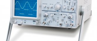
About virtual oscilloscopes.
I once had a fix idea: sell an analog oscilloscope and buy a digital USB oscilloscope to replace it. But, having wandered around the market, I discovered that the most budget oscilloscopes “start” at $250, and the reviews about them are not very good. More serious devices cost several times more.
So, I decided to limit myself to an analog oscilloscope, and to build some diagram for the site, use a virtual oscilloscope.
I downloaded several software oscilloscopes from the network and tried to measure something, but nothing good came of it, since either it was not possible to calibrate the device, or the interface was not suitable for screenshots.
I had already abandoned this matter, but when I was looking for a program to measure the frequency response, I came across the “AudioTester” software package. I didn’t like the analyzer from this kit, but the Osci oscilloscope (hereinafter I will call it “AudioTester”) turned out to be just right.
This device has an interface similar to a conventional analog oscilloscope, and the screen has a standard grid that allows you to measure amplitude and duration. https://oldoctober.com/
The disadvantages include some instability of work. The program sometimes freezes and in order to reset it you have to resort to the help of Task Manager. But all this is compensated by the familiar interface, ease of use and some very useful functions that I have not seen in any other program of this type.
Attention! The AudioTester software package includes a low frequency generator. I don't recommend using it because it tries to control the audio card driver itself, which can result in permanent audio muting. If you decide to use it, take care of a restore point or an OS backup. But, it’s better to download a normal generator from “Additional materials”.
Another interesting program for the Avangard virtual oscilloscope was written by our compatriot O.L. Zapisnykh.
This program does not have the usual measuring grid, and the screen is too large for taking screenshots, but it does have a built-in amplitude voltmeter and frequency meter, which partially compensates for the above disadvantage.
Partly because at low signal levels both the voltmeter and the frequency meter begin to lie a lot.
However, for a novice radio amateur who is not used to perceiving diagrams in Volts and milliseconds per division, this oscilloscope may be quite suitable. Another useful property of the Avangard oscilloscope is the ability to independently calibrate the two available scales of the built-in voltmeter.
So, I will talk about how to build a measuring oscilloscope based on the AudioTester and Avangard programs. Of course, in addition to these programs, you will also need any built-in or separate, most budget audio card.
Actually, all the work comes down to making a voltage divider (attenuator) that would cover a wide range of measured voltages. Another function of the proposed adapter is to protect the audio card input from damage when high voltage comes into contact with the input.
Return to top to menu.
Self-powered option
At home, radio amateurs usually use stationary devices. But sometimes a situation arises when you need to repair something located far from home. In this case, you will need a portable, self-powered oscilloscope.
Before starting assembly, prepare the following components:
- Unnecessary Bluetooth headphones or audio module.
- Android tablet or smartphone.
- Lithium-ion battery size 18650.
- Holder for him.
- Charge controller.
- Jack 2.1 x 5.5 mm.
- Connector for connecting test leads.
- The probes themselves.
- Switch.
- Plastic shoe sponge box.
- Shielded wire with a cross section of 0.1 mm².
- Tact button.
- Hot melt adhesive.
You need to disassemble the wireless headset and remove the control board from it. Unsolder the microphone, power button and battery from it. Set the board aside.
Instead of Bluetooth headphones, you can use a Bluetooth audio module.
Use a knife to scrape off the remaining sponge from the box and clean it well using detergents. Wait until it dries and cut out holes for the button, switch and connectors.
Solder the wires to the sockets, holder, button and switch. Place them in place and secure with hot glue.
The wires must be connected as shown in the diagram:
Explanation of symbols:
- Holder.
- Switch.
- Contacts “BAT + and “BAT –”.
- Charge controller.
- Contacts “IN + and “IN –”.
- Jack 2.1 x 5.5 mm connector.
- Contacts “OUT+ and “OUT –”.
- Battery contacts.
- Control board.
- Power button contacts.
- Tact button.
- Probe socket.
- Microphone contacts.
Next, solder the wires to the charge controller and control board, then place them inside the case and secure with hot glue. Close the box with a lid and snap it shut.
Then download the virtual oscilloscope application from the play market and install it on your smartphone. Turn on the Bluetooth module and synchronize it with your smartphone. Connect the probes to the oscilloscope and open its software on your phone.
When you touch the signal source with the probes, a curve showing the signal level will appear on the screen of your Android device. If it doesn't appear, it means a mistake was made somewhere.
You should check the correct connection and serviceability of the internal components. If everything is ok, you need to try to start the oscilloscope again.
Technical data and scope.
Since there is an isolation capacitor in the input circuits of the audio card, the oscilloscope can only be used with a “closed input”. That is, only the variable component of the signal can be observed on its screen. However, with some skill, using the AudioTester oscilloscope you can also measure the level of the DC component. This can be useful, for example, when the multimeter reading time does not allow you to record the amplitude value of the voltage on a capacitor charging through a large resistor.
The lower limit of the measured voltage is limited by the noise level and background level and is approximately 1 mV. The upper limit is limited only by the parameters of the divider and can reach hundreds of volts.
The frequency range is limited by the capabilities of the audio card and for budget audio cards is: 0.1Hz... 20kHz (for a sine wave signal).
Of course, we are talking about a rather primitive device, but in the absence of a more advanced device, this one may well do.
The device can help in repairing audio equipment or be used for educational purposes, especially if it is supplemented with a virtual low-frequency generator. In addition, using a virtual oscilloscope it is easy to save a diagram to illustrate any material, or for posting on the Internet.
Return to top to menu.
Programs that emulate the operation of an oscilloscope
Virtual oscilloscopes process signals received at the input of a computer or laptop. These programs have an interface similar to the screen of a real oscilloscope. Some applications are designed to work with devices based on sound cards, others interact with USB oscilloscopes.
Programs running through audio input:
- Digital Oscilloscope;
- SoundCard Oszilloscope;
- Russian development "Avangard".
Software for USB oscilloscopes:
- Aktakom OscilloscopePro.
- Simplescope.
All virtual devices are two-channel, equipped with frequency generators and analyzers. The measurements and oscillograms can be saved on a PC. Usually they do not need to be installed. After unpacking the archive and launching the program, the interface of a real oscilloscope with settings regulators appears.
Working methods
A computer is a digital device, so to measure an analog parameter it is necessary to convert the signal into discrete form. For this, an ADC is used - an analog-to-digital converter. A DAC (digital-to-analog converter) is used to output data.
The computer's sound card samples incoming analog signals that are connected to the LINE IN and MIC inputs.
Therefore, the audio card can be used as an ADC to supply the measured signal to a computer or laptop. Since a person hears sound in the range of 4Hz-20kHz, then, accordingly, the audio card operates in the low-frequency spectrum. The resulting oscilloscope will also operate in the specified range.
Another drawback in the operation of the “sound” oscilloscope is the limitation on the voltage supplied to the input. It should be within 0.5V for MIC input and up to 2V for LINE IN. Connecting a signal with an amplitude of more than 2V will damage the sound card or computer.
Due to the design features of the audio card - the presence of a decoupling capacitor at the input, the direct component of the electric current will not be shown on the oscilloscope. But using the app, you can measure it. It is better to send the signal to the LINE IN input, since it has the lowest noise level. The minimum signal level that can be measured is about 1 mV.
The use of such oscilloscopes is limited in frequency. They can take readings from amplifiers, tape recorders, various audio devices, as well as microcircuits operating at frequencies up to 20 kHz.
At high frequencies, USB oscilloscopes with more capabilities are used. The disadvantage of such devices is their high price.
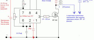
Electrical diagram of the oscilloscope hardware.
The drawing shows the hardware part of the oscilloscope - “Adapter”.
To build a two-channel oscilloscope, you will have to duplicate this circuit. The second channel can be useful for comparing two signals or for connecting external synchronization. The latter is provided in AudioTester.
Resistors R1, R2, R3 and Rin. – voltage divider (attenuator).
The values of resistors R2 and R3 depend on the virtual oscilloscope used, or more precisely on the scales it uses. But, since the “AudioTester” has a division price that is a multiple of 1, 2 and 5, and the “Avangard” has a built-in voltmeter with only two scales interconnected by a ratio of 1:20, then using an adapter assembled according to the above the circuit should not cause inconvenience in both cases.
The input impedance of the attenuator is about 1 megohm. In a good way, this value should be constant, but the design of the divider would be seriously complicated.
Capacitors C1, C2 and C3 equalize the amplitude-frequency response of the adapter.
Zener diodes VD1 and VD2, together with resistors R1, protect the linear input of the audio card from damage in the event of accidental high voltage entering the adapter input when the switch is in the 1:1 position.
I agree that the presented scheme is not elegant. However, this circuit solution makes it possible in the simplest way to achieve a wide range of measured voltages using only a few radio components. An attenuator built according to the classical scheme would require the use of high-megaohm resistors, and its input impedance would change too significantly when switching ranges, which would limit the use of standard oscilloscope cables designed for an input impedance of 1 MOhm.
Return to top to menu.
Assembling an oscilloscope from a tablet
To stabilize the signal and expand the input voltage range, you can use an oscilloscope circuit for a tablet. It has been used for a long time and successfully to assemble devices for the computer.
For this purpose, KS 119 A zener diodes with resistors of 10 and 100 kOhm are used. The first resistor and zener diodes are connected in parallel. A second and more powerful resistor is connected to the input of the electrical circuit. This expands the maximum voltage range. Ultimately, additional interference disappears and the voltage increases to 12 volts.
Necessary software for assembling an oscilloscope based on a tablet and Android
To work with such a circuit, you will need a program that can draw graphs based on the incoming audio signal. Many such options can be easily found in the Market. With them, you can choose additional calibration and achieve maximum accuracy for a professional oscilloscope from a tablet or other functional device.
Wideband frequency using a separate gadget
A wide range of frequencies with the help of a separate gadget is achieved by its set-top box with an analog-to-digital converter, which provides signal transmission in a digital version. Due to this, higher measurement accuracy is achieved. In practice, it is a portable display that accumulates information from individual devices.
Protection from the "fool".
To protect the linear input of the audio card from accidental high voltage, zener diodes VD1 and VD2 are installed parallel to the input.
Resistor R1 limits the current of the zener diodes to 1 mA, at a voltage of 1000 Volts at the 1:1 input.
If you really intend to use an oscilloscope to measure voltages up to 1000 Volts, then as resistor R1 you can install MLT-2 (two-watt) or two MLT-1 (one-watt) resistors in series, since the resistors differ not only in power, but also according to the maximum permissible voltage.
Capacitor C1 must also have a maximum allowable voltage of 1000 Volts.
A little clarification of the above. Sometimes you want to look at a variable component of relatively small amplitude, which nevertheless has a large constant component. In such cases, you need to keep in mind that on the screen of an oscilloscope with a closed input, you can only see the alternating voltage component.
The picture shows that with a constant component of 1000 Volts and a swing of the variable component of 500 Volts, the maximum voltage applied to the input will be 1500 Volts. Although, on the oscilloscope screen we will only see a sine wave with an amplitude of 500 Volts.
Return to top to menu.
Problems when creating an oscilloscope
Problems can arise both for a beginner and for someone who knows how to make an oscilloscope in practice from an ordinary home computer. To minimize the chances, it is better to study the entire theory before work or setup, and also buy materials with a reserve if there is a need to make a console.
Possible difficulties:
- Problems with the circuit. The circuit for a simple oscilloscope is easy in itself, but if difficulties arise, you can use video guides.
- Programs are not installed. If the software refuses to work on the computer, check compatibility (complies with operating system requirements, presence of all necessary parts in the PC).
- The result is not displayed on the screen. This is an internal configuration problem - specify the correct path so that saving and reproducing analysis results occurs correctly.
Most of the problems that arise can be easily solved with subsequent attempts, minimal theoretical knowledge and experience - you just have to have a little patience.
How to measure the output impedance of a line output?
You can skip this paragraph. It is designed for lovers of small details.
The output impedance (output impedance) of a line output designed to connect phones (headphones) is too low to have a significant impact on the accuracy of the measurements we will perform in the next paragraph.
So why measure output impedance?
Since we will use a virtual low-frequency signal generator to calibrate the oscilloscope, its output impedance will be equal to the output impedance of the Line Out of the sound card.
By making sure that the output impedance is low, we can prevent gross errors when measuring the input impedance. Although, even under the worst circumstances, this error is unlikely to exceed 3... 5%. Frankly, this is even less than the possible measurement error. But it is known that errors have a habit of “running up”.
When using a generator to repair and tune audio equipment, it is also advisable to know its internal resistance. This can be useful, for example, when measuring ESR (Equivalent Series Resistance) or simply the reactance of capacitors.
Thanks to this measurement, I was able to identify the lowest impedance output in my audio card.
If the audio card has only one output jack, then everything is clear. It is both a line output and an output for phones (headphones). Its impedance is usually small and does not need to be measured. These are the audio outputs used in laptops.
When there are as many as six sockets and there are a couple more on the front panel of the system unit, and each socket can be assigned a specific function, then the output impedance of the sockets can differ significantly.
Typically, the lowest impedance corresponds to the light green jack, which by default is the line output.
| Color/location | Switch state | |
| Phones (Ohm) | Line Out (Ohm) | |
| Lime / Rear | 5 | 230 |
| Grey/Rear | 7 | 230 |
| Lime/Front | 12 | 80 |
| Laptop | 0,7 | Doesn't switch |
An example of measuring the impedance of several different audio card outputs set to “Telephones” and “Line Out” modes.
As can be seen from the formula, the absolute values of the measured voltage do not play a role, therefore these measurements can be made long before calibrating the oscilloscope.
Calculation example.
R1 = 30 Ohm.
U1 = 6 divisions.
U2 = 7 divisions.
Rx = 30(7 – 6) / 6 = 5 (Ohm).
Return to top to menu.
Converting a Computer to an Oscilloscope
After clarifying the initial computer data and personal needs, they begin to select an electrical circuit.
To get acquainted with professional solutions, you can study the designs of serial measuring instruments
Set-top box diagram
For high-quality reproduction without extensive practical experience, it is better to choose relatively simple designs. However, the electrical circuit presented below is quite capable of ensuring minimal signal distortion while simultaneously performing protective functions.
This adapter circuit can be created quickly without unnecessary difficulties
Description:
- the set-top box resistors are evaluated in conjunction with the Rin of the computer in order to correctly calculate the divider parameters;
- capacitors equalize the frequency response;
- Zener diodes installed in the manner shown in the figure prevent damage to the computer’s audio input when a high-amplitude signal is supplied (switch position “1:1”);
- additional current protection is provided by R1.
You can hardly count on complete passport data, especially if you have old computer equipment. Most likely, you will have to measure the impedance at the sound card input. To do this, a reference signal (50 Hz, sinusoid) is created at the output of the same block using a special “Virtual Generator” program. The following calculation is performed using the formula:
Rx=R1*(U1/(U2-U1)).
Example:
60*(120/(520-120))= 18 kOhm.
Knowing the input resistance, create a voltage divider using one of the presented circuits
Set-top box collection
To eliminate the parasitic influence of external electromagnetic radiation, the set-top box is placed in a metal case. It can be created from a suitable duralumin sheet with a thickness of 1.5-2 mm. A CP-50 type connector is attached to the input so that standard probes can be connected without problems. The output is a flexible cable with a Jack plug that matches the input jack of the computer audio card. For assembling a simple electrical circuit, surface-mounting technology is quite suitable.
How to measure the input impedance of a linear input?
To calculate the attenuator for the linear input of an audio card, you need to know the input impedance of the linear input. Unfortunately, it is impossible to measure the input resistance using a conventional multimeter. This is due to the fact that there are isolation capacitors in the input circuits of audio cards.
The input impedances of different audio cards can vary greatly. So, this measurement will still have to be done.
To measure the input impedance of an audio card using alternating current, you need to apply a sinusoidal signal with a frequency of 50 Hz to the input through a ballast (additional) resistor and calculate the resistance using the given formula.
A sinusoidal signal can be generated in a software low-frequency generator, a link to which is in the “Additional Materials”. Amplitude values can also be measured using a software oscilloscope.
The picture shows the connection diagram.
The voltages U1 and U2 must be measured with a virtual oscilloscope in the corresponding positions of the SA switch. There is no need to know the absolute voltage values, so the calculations are valid until the device is calibrated.
Calculation example.
R1 = 50kOhm.
U1 = 100
U2 = 540
Rx = 50 * 100 / (540 – 100) ≈ 11.4 (kOhm).
| Color/Location | Impedance (kOhm) |
| Red/Rear | 82 |
| Black/Rear | 75 |
| Lime/Front | 11,4 |
| Pink/Front | 50 |
| Laptop | 8,5 |
Here are the results of impedance measurements of various line inputs.
As you can see, the input resistances differ significantly, and in one case, almost an order of magnitude.
Return to top to menu.
Oscilloscope and its functions
This is an electronic device on the screen of which the waveform is observed. A number of options are available during operation:
- recording instantaneous characteristics;
- analogy of phase shifts and signal shapes with other pulses;
- control and monitoring of sinusoidal, triangular and square waves;
- pulse sweep to measure rise time.
Simply put, this is a television receiver where the electrical signal is monitored visually. Knowing the principles of operation and the circuit diagram of the device, they assemble the oscilloscope with their own hands.
Devices can be classified according to the following indicators:
- features of work and purpose;
- number of signals viewed at once;
- method of information processing;
- type of playback device.
According to the features of the work, they are divided into models: high-speed, stroboscopic, universal, memory and special. The number of simultaneously sent signals is one, two or more.
Important! Multichannel n-oscilloscopes display n-graphs on the screen, reading readings from the n-th number of signal inputs. Analog and digital devices share methods for processing received information.
Signal display units are represented by cathode ray tubes “CRT” or matrix panels
Analog and digital devices share methods for processing the received information. Signal display units are represented by cathode ray tubes (CRTs) or matrix panels.
How to calculate a voltage divider (attenuator)?
The maximum unlimited amplitude of the audio card input voltage, at the maximum recording level, is about 250 mV. A voltage divider, or as it is also called an attenuator, allows you to expand the range of measured voltages of an oscilloscope.
The attenuator can be constructed using different circuits, depending on the division coefficient and the required input resistance.
Here is one of the divider options that allows you to make the input resistance a multiple of ten. Thanks to the additional resistor Rext. you can adjust the resistance of the lower arm of the divider to some round value, for example, 100 kOhm. The disadvantage of this circuit is that the sensitivity of the oscilloscope will depend too much on the input impedance of the audio card.
So, if the input impedance is 10 kOhm, then the division ratio of the divider will increase tenfold. It is not advisable to reduce the resistor of the upper arm of the divider, since it determines the input resistance of the device, and is the main element in protecting the device from high voltage.
So, I suggest you calculate the divider yourself based on the input impedance of your audio card.
There is no error in the picture; the divider begins to divide the input voltage already when the scale is 1:1. Calculations, of course, need to be done based on the actual ratio of the divider arms.
In my opinion, this is the simplest and at the same time the most universal divider circuit.
Using the presented formulas, you can calculate the attenuator for the adapter if you agree with the proposed circuit.
An example of divisor calculation.
Initial values.
R1 – 1007 kOhm (result of measuring a 1 mOhm resistor).
Rin. – 50 kOhm (I chose the higher-impedance input of the two available on the front panel of the system unit).
Calculation of the divider in the switch position 1:20.
First, using formula (1), we calculate the division coefficient of the divider, determined by resistors R1 and Rin.
(1007 + 50)/ 50 = 21,14 (once)
This means that the total division ratio in the switch position 1:20 should be:
21,14*20 = 422,8 (once)
We calculate the resistor value for the divider.
1007*50 /(50*422,8 –50 –1007) ≈ 2,507 (kOhm)
Calculation of the divider in the switch position 1:100.
We determine the overall division ratio at the switch position of 1:100.
21,14*100 = 2114 (once)
We calculate the resistor value for the divider.
1007*50 / (50*2114 –50 –1007) ≈ 0,481 (kOhm)
To make calculations easier, take a look at this link: How to pair Notepad with the Windows Calculator to make calculations easier?
If you are going to use only the Avangard oscilloscope and only in the 1:1 and 1:20 ranges, then the accuracy of resistor selection may be low, since the Avangard can be calibrated independently in each of the two available ranges. In all other cases, you will have to select resistors with maximum accuracy. How to do this is written in the next paragraph.
If you doubt the accuracy of your tester, then you can adjust any resistor with maximum accuracy by comparing ohmmeter readings.
To do this, instead of a permanent resistor R2, a tuning resistor R* is temporarily installed. The resistance of the trimming resistor is selected so as to obtain the minimum error in the corresponding division range.
Then the resistance of the trimming resistor is measured, and the constant resistor is already adjusted to the resistance measured by an ohmmeter. Since both resistors are measured with the same device, the ohmmeter error does not affect the measurement accuracy.
And these are a couple of formulas for calculating the classic divisor. A classic divider can be useful when a high input impedance of the device (mOhm/V) is required, but you don’t want to use an additional dividing head.
Return to top to menu.
Oscilloscope connected via USB
There are many options for making homemade USB oscilloscopes, but not all of them are accessible to beginners. The simplest option would be to assemble it from ready-made components. They are sold in radio stores. A cheaper option would be to buy these radio components in Chinese online stores, but you need to remember that components purchased in China may arrive in a faulty condition, and money for them is not always returned. After assembly, you should get a small set-top box that connects to a PC.
This version of the oscilloscope has the highest accuracy. If the problem arises of which oscilloscope to choose for repairing laptops and other complex equipment, it is better to opt for it.
For production you will need:
- Board with separated tracks.
- Processor CY7C68013A.
- AD9288−40BRSZ analog-to-digital converter chip.
- Capacitors, resistors, chokes and transistors. The values of these elements are indicated on the circuit diagram.
- Soldering gun for sealing SMD components.
- Wire in varnish insulation with a cross-section of 0.1 mm².
- Toroidal core for winding a transformer.
- A piece of fiberglass.
- Soldering iron with a grounded tip.
- Solder.
- Flux.
- Solder paste.
- Memory chip EEPROM flash 24LC64.
- Frame.
- USB connector.
- Socket for connecting probes.
- Relay TX-4.5 or other, with a control voltage of no more than 3.3 V.
- 2 AD8065 operational amplifiers.
- DC-DC converter.
You need to collect according to this scheme:
Usually, radio amateurs use the etching method to make printed circuit boards. But you won’t be able to make a double-sided printed circuit board with a complex layout in this way yourself, so you need to order it in advance from a factory that produces such boards.
To do this, you need to send a drawing of the board to the factory, according to which it will be manufactured. The same factory makes boards of different quality. It depends on the options selected when placing your order.
In order to receive a good payment in the end, you need to specify the following conditions in your order:
- The thickness of fiberglass is at least 1.5 mm.
- The thickness of the copper foil is at least 1 OZ.
- Through metallization of holes.
- Tinning of contact pads with lead-containing solder.
After receiving the finished board and purchasing all the radio components, you can begin assembling the oscilloscope.
The first to assemble is a DC-DC converter that produces voltages of +5 and -5 volts.
It must be assembled on a separate board and connected to the main one using a shielded cable .
Solder the microcircuits to the main board carefully, without overheating them. The temperature of the soldering iron should not be higher than three hundred degrees, otherwise the soldered parts will fail.
After installing all the components, assemble the device into a suitable-sized case and connect it to the computer with a USB cable. Close jumper JP1.
You need to install and launch the Cypress Suite program on your PC, go to the EZ Console tab and click on LG EEPROM. In the window that appears, select the firmware file and press Enter. Wait for the message Done to appear, indicating the successful completion of the process. If the message Error appears instead, it means that an error occurred at some stage. You need to restart the flasher and try again.
After flashing the firmware, your self-made digital oscilloscope will be completely ready for use.
How to select or adjust voltage divider resistors?
Since radio amateurs often have difficulty finding precision resistors, I will talk about how you can adjust common resistors for a wide range of applications with high accuracy.
High-precision resistors are only several times more expensive than conventional ones, but on our radio market they are sold for 100 pieces, which makes their purchase not very advisable.
Using trim resistors.
As you can see, each arm of the divider consists of two resistors - a constant one and a trimmer one.
Disadvantage: cumbersome. Accuracy is limited only by the available accuracy of the measuring instrument.
Selection of resistors.
Another way is to select pairs of resistors. Accuracy is ensured by selecting pairs of resistors from two sets of resistors with a large spread. First, all resistors are measured, and then pairs are selected whose sum of resistances most closely matches the circuit.
It was in this way, on an industrial scale, that the divider resistors for the legendary TL-4 tester were adjusted.
The disadvantage of this method is that it is labor intensive and requires a large number of resistors.
The longer the list of resistors, the higher the selection accuracy.
Adjusting resistors using sandpaper.
Even industry does not shy away from adjusting resistors by removing part of the resistive film.
However, when adjusting high-resistance resistors, it is not allowed to cut through the resistive film. For high-resistance film resistors MLT, the film is applied to a cylindrical surface in the form of a spiral. Such resistors must be filed extremely carefully so as not to break the circuit.
Precise adjustment of resistors in amateur conditions can be done using the finest sandpaper - “null sandpaper”.
First, the protective layer of paint is carefully removed from the MLT resistor, which obviously has a lower resistance, using a scalpel.
The resistor is then soldered to the “ends”, which are connected to the multimeter. By careful movements of the “zero” skin, the resistance of the resistor is brought to normal. When the resistor is adjusted, the cut area is covered with a layer of protective varnish or glue.
What a “zero” skin is is written here.
In my opinion, this is the fastest and easiest way, which, nevertheless, gives very good results.
Return to top to menu.
How to make a 15 V model
During assembly, linear resistors are used, the resistance of which is at the limit level - 5 MΩ. This allows the zener diode to operate in a gentle mode. When selecting capacitors, the threshold voltage is first measured by the tester.
Attention! The test results obtained, when using tuning resistors for the device, can be inaccurate. It is appropriate to use linear resistors
When assembling, do not forget to mount a port connected through a probe to the microcircuit, while a divider is connected through the bus. The use of vacuum diodes in the assembly will allow you to control the level of oscillation amplitude.
15V Oscilloscope
Construction and details.
The elements of the adapter circuit are housed in a rectangular duralumin housing.
The attenuator division ratio is switched using a toggle switch with the middle position.
The standard CP-50 connector is used as the input jack, which allows the use of standard cables and probes. Instead, you can use a regular 3.5mm Jack audio jack.
Output connector: standard 3.5mm audio jack. The adapter connects to the linear input of the audio card using a cable with two 3.5mm jacks at the ends.
The assembly was carried out using the hinged mounting method.
To use the oscilloscope you will need another cable with a probe at the end.
How to make it is written in detail here.
Return to top to menu.
Device and purpose
The circuit diagram of an oscilloscope is difficult for a novice radio amateur to understand, so it should not be considered as a whole, but first broken down into separate blocks:
Each block is a separate chip, or board .
The signal from the device under test is supplied through the Y input to the input divider, which sets the sensitivity of the measuring circuit. After passing through the pre-amplifier and delay line, it reaches the final amplifier, which controls the vertical deflection of the indicator beam. The higher the signal level, the more the beam is deflected. This is how the vertical deflection channel is designed.
The second channel is horizontal deflection, needed to synchronize the beam with the signal. It allows you to keep the beam in the place specified by the settings.
Without synchronization, the beam will float off the screen.
There are three types of synchronization: from an external source, from the network and from the signal being studied. If the signal has a constant frequency, then it is better to use synchronization from it. The external source is usually a laboratory signal generator. Instead, a smartphone with a special application installed on it is suitable for these purposes, which modulates the pulse signal and outputs it to the headphone jack.
Oscilloscopes are used in the repair, design and configuration of various electronic devices. This includes diagnosing vehicle systems, troubleshooting household appliances, and much more.
The oscilloscope measures:
- Signal level.
- Its shape.
- Pulse rise rate.
- Amplitude.
It also allows you to sweep a signal down to thousandths of a second and view it in great detail.
Most oscilloscopes have a built-in frequency counter.
How to calibrate a virtual oscilloscope?
To calibrate an oscilloscope, you need to have at least some kind of measuring instrument. Any pointer tester or digital multimeter that you trust will do.
Due to the fact that some testers have too high an error when measuring alternating voltage up to 1 Volt, we perform calibration at the maximum possible voltage, but unlimited in amplitude.
Before calibration, we make the following settings.
Disable the audio card equalizer.
“Line output level”, “WAVE level”, “Line input level” and “Recording level” are set to the maximum gain position. This will ensure repeatability of the result during further measurements.
Having reset the generator settings just in case using Command > Get Generator Default Setting, set the “Gain” (level) to 0db.
We select the generator frequency of 50Hz using the “Frequency Presets” switch, since all amateur instruments for measuring alternating voltage can operate at this frequency, and our adapter cannot yet operate correctly at higher frequencies.
Switch the adapter input to 1:1 mode.
Looking at the oscilloscope screen, use the Trim generator knob to select the maximum unlimited signal level.
The signal may be limited both at the input of the audio card and at its output, and the accuracy of calibration may be significantly reduced. AudioTester even has a special overload indicator, which is highlighted in red in the screenshot.
Using a tester, we measure the voltage at the generator output and calculate the corresponding amplitude value.
Example.
Voltmeter reading = 1.43 Volts (rms).
We get the amplitude value.
1,432*√2 = 2,025 (Volt)
The “Options > Calibrate” command brings up the “AudioTester” calibration window.
And although the dimension in “mVrms” is indicated next to the input window, which in theory should mean the root mean square value, in reality, in the “oszi v2.0c” oscilloscope from the “AudioTester” kit, the entered values correspond to... it’s not clear what. Which, however, does not at all prevent you from accurately calibrating the device.
By entering values in small increments, you can precisely adjust the size of the sine wave image to the amplitude value calculated above.
The picture shows that the signal amplitude is a little more than two divisions, which corresponds to 2.02 Volts.
The accuracy of the display of the amplitude of the signals received from the 1:20 and 1:100 inputs will depend on the accuracy of the selection of the corresponding divider resistors.
When calibrating the Avangard oscilloscope, the values obtained during measurement by the tester must also be multiplied by √2, since both the voltmeter and the Avangard calibrator are designed for amplitude values.
Enter the resulting value into the calibration window in millivolts - 2025 and press Enter.
To calibrate the second range of the Avangard oscilloscope, which is about, you must first calculate the real division factor by comparing the readings of the built-in voltmeter in two divider ranges: 1:1 and 1:20. The oscilloscope voltmeter should be in the “12.5” position
Example.
122 / 2323 = 19,3
Then you need to correct the “calibr” file, which can be opened in Notepad. On the left is the file before editing, and on the right is after.
The "calibr" file is located in the same directory as the current copy of the program.
In the eighth line we enter the real division coefficient corresponding to the divider of the first (left) channel.
If you have built a two-channel adapter, then in the ninth line we make an amendment for the second (right) channel.
Return to top to menu.
Functional Features
The main function of an oscilloscope is to provide a graph of voltage over time. Typically the Y axis represents voltage and the X axis represents time. This can be useful:
- to measure parameters such as clock frequencies, duty cycles of pulse-width modulated signals, propagation delay, or rise and fall times of sensor signals;
- to warn the user about the presence of failures in the system or interceptors;
- for research (observation, recording, measurement) of amplitude and time parameters.
For information. The measurement ranges are huge. For example, on a relatively cheap oscilloscope you can adjust from 5 mV/cm to 5 V/cm (vertical scale) and from 2 µs/cm to 20 s/cm (horizontal scale).
Other device features:
- Display and calculate the frequency and amplitude of an oscillating signal;
- Show voltage and time. This function is most often used in experimental laboratories;
- Help resolve any faulty project components by reviewing the expected outcome;
- Show changes in AC or DC voltage.
Waveforms of parameters
To better understand the functions of the device, you need to become familiar with the terms used and what they represent:
- Bandwidth indicates the range of frequencies that the device can accurately measure;
- Gain accuracy measures how accurately the vertical system attenuates or enhances the signal. The value is indicated in percentage error;
- Time base or horizontal precision indicates how accurately the horizontal system represents the timing of a signal. This is displayed as a percentage error;
- Rise time is another way of describing the usable frequency range of an instrument. The rise time must be taken into account when measuring pulses and steps. The instrument cannot accurately display pulses with a rise time faster than the oscilloscope's specified rise time;
- Vertical sensitivity measures how much a vertical amplifier can boost a weak signal. Vertical sensitivity is usually specified in mV/div (millivolts per division). The smallest voltage that a general purpose oscilloscope can detect is typically about 1 mV per vertical division of the screen;
- Sweep Speed – This setting specifies how quickly the trace can move across the screen. This is usually specified in ns/div (nanoseconds per division);
- The sampling rate on a digital oscilloscope indicates how many samples per second the A to D converter can take. The maximum sampling rate is usually specified in MPs (megapixels per second). The faster the oscilloscope can sample, the more accurately it can represent the subtle details of the signal. The minimum sample rate can also be important if you need to watch slowly changing signals over long periods of time. Typically, the sampling rate changes with changes made to the control to maintain a constant number of waveform points in the waveform record;
- The record length of a digital oscilloscope indicates the number of waveforms the device can acquire per record. The maximum recording length depends on its memory. It is possible to obtain a detailed image of the signal over a short period of time, or a less detailed image over a longer period of time.
How to equalize the amplitude-frequency response of the adapter?
The linear input of the audio card, and the adapter circuits themselves, have some input capacitance. The reactance of this capacitance changes the division ratio of the divider at high frequencies.
To equalize the frequency response of the adapter in the 1:1 range, you need to select the capacitance of capacitor C1 so that the amplitude of the signal at a frequency of 50 Hz is equal to the amplitude of the signal with a frequency of 18-20 kHz.
Resistors R2 and R3 reduce the influence of the input capacitance and create an increase in the frequency response in the high frequency region. This rise can be compensated by selecting capacitors C2 and C3 in the corresponding ranges of 1:20 and 1:100.
I selected the following capacitances: C1 – 39pF, C2 – 10nF, C3 – 0.1nF.
Now that the Y channel of the oscilloscope's vertical deviation is calibrated and linearized, you can see what certain periodic signals, and more, look like. “AudioTester-e” has “waiting scan synchronization”.
Return to top to menu.
Use in everyday life
During operation, the following recommendations should be used:
- the computer together with the set-top box is grounded before performing measuring operations;
- use a range suitable for a certain signal amplitude;
- stop working if the electrical insulation is damaged or other dangerous faults are detected.
The presented oscilloscopes for PC, when properly assembled and configured, provide fairly high accuracy. However, we must not forget that even specialized devices in this category are intended rather to study the shape of signals. Such problems can be solved using the equipment discussed in the publication.
The best oscilloscope software for Windows PC
The following sections provide brief overviews of popular specialized programs. When choosing, you should pay attention to ease of learning, interface language, and other details, taking into account the needs of a particular user.
FrequencyAnalyzer
The program was created for processing audio signals. It is permissible to change the measurement frequency. User-selectable 8 (16) digit conversion helps establish the required accuracy. The disadvantage is the lack of a Russified version.
Winscope
This online oscilloscope does more than just show the signal. When you select the appropriate mode, Lissajous figures are displayed on the screen. The user can examine the spectral distribution in the range from 20Hz to 20kHz.
Sound oscilloscope
The 2ray Oscilloscope is well suited for studying two signals. If necessary, waveforms can be saved as graphic files. The clear interface simplifies the use of the program.
Oscilloscope Spectrum in real time
Multi-Instrument contains not only an oscilloscope, but also a generator. This software suite is complemented by a spectrum analyzer. Such equipment is suitable for complex testing of radio equipment.
Product customization
After assembling the USB oscilloscope, the last step is to the EEPROM flash 24LC64 memory chip For this:
- Download and install the Cypress Suite application on your computer.
- Launch the program and go to the EZ Console .
- Click on the inscription “ LG EEPROM ”.
- A window with the firmware file . Select it and run it with the Enter .
- If the error “ Error ” appears, start the firmware operation again.
- After the process has completed successfully, the message “ Done ” should appear. The oscilloscope is ready for use.
Before launching an oscilloscope based on an external audio adapter, do the following:
- Save the files miniscope.exe, miniscope.ini and miniscope.log from the downloaded archive in a separate folder. Open miniscope.exe .
- After starting the program, go to the settings and perform the actions shown in the pictures.
The device is ready for use.
Calibration is necessary for the device, which operates through an attenuator and an internal sound card. To do this, apply a signal with a known amplitude and frequency to the gadget. Having achieved a stable scan, turn on the measuring grid . By coordinating the actions of the trimming resistor with the adjustments on the control panel, bring the grid values to the original values.
If you cannot display the values correctly, you can adjust the grid using the audio controls on your computer. To do this, open the volume control located on the taskbar and, moving the slider, get the desired signal level.
Finished products must be grounded . Be careful when connecting a signal to the audio adapter port.
Purchasing an expensive oscilloscope can be an overwhelming task for a novice radio amateur. Various computer attachments and corresponding programs allow you to replace the device and make an oscilloscope from your computer. In addition to saving money, it becomes possible to save the data of the measured signal on a computer and automate the calculations of parameters.
Using PPR1 series resistors
Devices containing elements of this line are very popular. Due to their high sensitivity, they are used for monitoring electrical equipment. To create this meter you will need a CRT, a pulse modulator, a rectifier and contactors with plates. The installation of a kenotron is justified by the accuracy of the readings obtained. The operational type device requires the installation of a controller.
The resistance value is not higher than 34 Ohms, and the signal conductivity is 4.2-4.5 Ohms. A USB port is connected through a low conductivity modulator. Spectral expanders for the circuit are taken of the pulse type.
Important! It is necessary to organize voltage stabilization, fix the expander next to the comparator, which will reduce heat losses.
Converting a Computer to an Oscilloscope
After clarifying the initial computer data and personal needs, they begin to select an electrical circuit.
Set-top box diagram
For high-quality reproduction without extensive practical experience, it is better to choose relatively simple designs. However, the electrical circuit presented below is quite capable of ensuring minimal signal distortion while simultaneously performing protective functions.
Description:
- the set-top box resistors are evaluated in conjunction with the Rin of the computer in order to correctly calculate the divider parameters;
- capacitors equalize the frequency response;
- Zener diodes installed in the manner shown in the figure prevent damage to the computer’s audio input when a high-amplitude signal is supplied (switch position “1:1”);
- additional current protection is provided by R1.
You can hardly count on complete passport data, especially if you have old computer equipment. Most likely, you will have to measure the impedance at the sound card input. To do this, a reference signal (50 Hz, sinusoid) is created at the output of the same block using a special “Virtual Generator” program. The following calculation is performed using the formula:
Example:
60*(120/(520-120))= 18 kOhm.
For your information. By installing a “tuning” resistor in parallel, you can precisely adjust the parameters of the divider.
More than just an oscilloscope
Modern laboratory digital oscilloscopes have unrivaled capabilities for studying the parameters of electrical signals. Such devices are found in many industrial workshops, but they are quite expensive and take up significant space on the desktop. The emergence of a new technological solution, implemented in the form of a USB set-top box, has made it possible to significantly reduce the cost of such devices and make them more accessible to radio amateurs - developers who repair electronic devices on their own. Such devices are practically not inferior in performance to their desktop counterparts.
USB models are miniature and do not require additional power supplies. They use the monitor screen as its own display, and allow you to view high-quality, high-resolution waveforms without distortion. Using a high-speed analog-to-digital converter (ADC), the input signal is converted to digital and transmitted to a PC for further processing. All received data can be saved to your hard drive. The devices are equipped with professional software with a clear user interface, with which you can control the device from the keyboard or mouse.
For a complete fault analysis of electronic circuits, it is usually necessary to use several devices: a logic analyzer, a spectrum analyzer, a chart recorder, a DDS generator. Some USB models contain a set of functions inherent in all the measuring instruments listed above, so purchasing such a device will make your life much easier and save money. One of the popular models in this segment is the Instrustar isds205a, a two-channel oscilloscope with a built-in data logger and spectrum analyzer.
The assortment of our online store includes Hantek USB oscilloscopes and Instrustar oscilloscopes - the world's leading manufacturers. You can buy a USB oscilloscope right now on our website. Our specialists will help you decide on the appropriate model and advise you on any issue that interests you.
Buy a USB oscilloscope and we will deliver it to you in any city in Russia, including the cities: Moscow, St. Petersburg, Novosibirsk, Yekaterinburg, Voronezh, Vladivostok, Krasnodar, Bryansk, Rostov-on-Don, Nizhny Novgorod, Chelyabinsk, Kazan, Krasnoyarsk , Omsk, Samara, Volgograd, Barnaul and others. We ship by EMS, Russian Post, SDEK, Business Lines and other transport companies. Payment upon receipt.