The quality of work when using inverter equipment is largely determined by the welding arc, its stability and reliability. However, surges and drops in the mains voltage can lead to a failure, and the arc spontaneously turns off. To avoid such situations and ensure stable operating conditions, a special device is used - an oscillator for the inverter. It is connected in parallel to the main device, and its function is to directly excite the arc and maintain it during the entire welding process.
Electrical circuit of the oscillator
Schemes and designs of welding oscillators may differ based on operating conditions and frequency of use.
Typically, these devices are connected in two ways:
- Consistently. This connection allows you to weld aluminum workpieces.
- Parallel. Used when working with stainless steel and for short-term welding.
A typical circuit consists of the following electrical components:
- Standard single-circuit spark gap design. This part is essentially a generator and ensures the formation of damped oscillations. It consists of a capacitor and inductors connected in parallel. Tungsten electrodes serve as contacts.
- There are two chokes, also made on the basis of inductors.
- Powerful step-up transformer. Converts standard mains voltage up to 6000 V and frequency up to 250 kHz.
- Transformer installed at the output. Transfers the generated voltage to the welding inverter circuit.
- Control circuit parts. This includes a stabilizer, start-up control elements, and a feedback loop with a current sensor.
- Security system elements. Made in the form of safety circuits that protect the circuit from overloads, and the worker himself from electric shock.
Tips for making a plasma cutter from an inverter with your own hands
As a rule, sheet metal is cut by plasma in large production facilities, and this is done when manufacturing parts of complex configurations. Industrial machines cut any metals: steel, copper, brass, aluminum, super-hard alloys. It is noteworthy that it is quite possible to make a plasma cutter yourself, although the capabilities of the device in this case will be somewhat limited. In large-scale production, a homemade manual plasma cutter is unsuitable, but it will be possible to cut out parts in your workshop, workshop or garage. There are practically no restrictions regarding the configuration and hardness of the workpieces being processed. However, they relate to cutting speed, sheet size and metal thickness.
Interaction with the inverter
The principle of operation of the equipment that stabilizes the operation of the inverter is to additionally supply high voltage to the electrode. It arrives periodically, along with the main output voltage of the welding unit itself. The voltage comes in the form of pulses with characteristic amplitude modulation. Their parameters can reach 6 kV, and the frequency is in the range of 150-500 kHz.
The duration of the generated pulses is insignificant, so they have a very low duty cycle, quite sufficient to obtain the required power - up to 300 W. Their impact leads to the formation of a short-term electrical breakdown between the part and the electrode, increasing the reliability of the contact. The oscillator starts when the electrode approaches the metal by approximately 5 mm. Under the influence of electrical impulses, the air gap is ionized, after which an instantaneous discharge occurs.
Types of oscillators
The welding oscillator can only be used as an additional device. By itself, it cannot provide a working process, due to its low power and the inability to independently connect and melt metals. The main purpose of the device is to ignite the arc and maintain its stable state without contact of the electrode with the metal surface.
This result was achieved by generating high voltage at high frequency, capable of breaking through the air space between the metal and the electrode. A zone of ionized air is created, through which the main welding current then begins to flow.
Depending on the operating modes, all oscillators can be divided into the following groups:
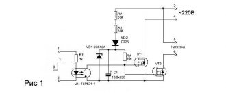
- Continuous devices (Fig. 1). Capable of delivering current with voltages of up to 6000 volts and a frequency of about 250 kHz. This additional potential combines with the main welding current to instantly ignite the arc at a certain distance from the workpiece. High frequency ensures stability, regardless of the inverter current parameters. Due to the low power, the additional current is completely safe for the welder. The device is connected to the inverter using a parallel or serial circuit. The latter option is used more often and does not require additional high voltage protection.
- Pulse oscillators (Fig. 2). Very convenient when performing welding work with alternating current. These devices have the ability to constantly maintain an arc with changing polarity of electricity. They easily ignite the arc in the absence of any contact between the electrode and the workpiece. In general, pulsed instruments have some advantages over continuous oscillators.
- Devices using storage capacitors. These components are installed in a general circuit and subsequently ensure the operation of the device in charge-discharge mode. The capacitors are filled with energy using a charging module. At the moment of operation, the energy of the charged capacitors is transferred to the arc. They are then disconnected from the discharge circuit and automatically connected to the charging module. If there is a threat of arc interruption, the capacitors are switched to the working circuit of the welding equipment.
Some nuances
If you need to choose an electrode for welding non-ferrous metals, you should pay attention to several basic subtleties. Very often, special wire is used for these purposes.
Very often, special wire is used for these purposes.
The wire comes in several different types and must be fully compatible with the materials that will be fastened together.
It should be remembered that such wire quickly loses all its useful properties when exposed to open air, especially if it is saturated with moisture.
The wire itself is quite soft, and therefore special roller mechanisms are used to feed it to the workspace.
Currently, wire of this class is produced in accordance with GOST in special coils.
In the photo below you can see the wire that is used for welding aluminum parts.
Rods are also very often used for welding aluminum. In this case, an arc welding machine operating under direct current is used.
In both cases, the welding scheme for non-ferrous metal remains virtually unchanged, with the exception of some details.
It should be remembered that all work should be carried out in the direction from right to left with smooth movements as carefully as possible.
The size of the arc from the metal surface to the electrode should not exceed two and a half millimeters.
A specially designed additive must be supplied, and the supply must be carried out in short forward-return movements.
Video:
The electrode and wire used should form a right angle with each other with a small protrusion from the tip of the device.
In the case where tungsten-based electrodes are used, even small transverse vibrations should not be allowed.
Particular importance should be paid to preparing the surface for work.
They must be thoroughly cleaned mechanically or chemically; in addition, the metal should be degreased using certain compounds.
In general, soldering is somewhat similar to welding metal, but there are several nuances.
Soldering is performed using fluxes and solder, and it forms a fairly strong bond between the metals.
Both soldering and welding of non-ferrous metals must be carried out not only in accordance with generally accepted technology, but also according to strictly established rules.
The devices and equipment used for this must be correctly configured in accordance with the selected modes and technical features of the workpieces.
You should also carefully select electrodes and filler materials, which must meet the requirements of GOST and satisfy the equipment.
Video:
Particular attention must be paid to compliance with safety regulations, especially if the work is performed at home. You should use special protective clothing that will help protect your skin from hot metal.
You should also use a mask while working.
You should use special protective clothing that will help protect your skin from hot metal. You should also use a mask while working.
If all the work is done in accordance with the technology and established rules, then the seam will be not only smooth and dense, but also of the highest quality.
In any case, you should approach the work as collectedly and responsibly as possible, taking into account all the subtleties and nuances, and then the welding process will be easy.
How to make the device yourself
If you have certain knowledge and practical skills in working with electronics, making an oscillator for an inverter yourself will not be difficult. There may be several options for the device, therefore, when choosing the most suitable scheme, it is necessary to determine the operating conditions and other initial data.
Typically, the following factors are taken into account:
- Purpose of the equipment. It is advisable to determine as accurately as possible what material you will have to work with. Each metal has its own characteristics, which are taken into account when drawing up the diagram.
- Basic parameters of current and voltage: alternating or direct, mains voltage characteristics, etc.
- The amount of permissible electrical power. Determined by the input power of conventional circuits, not exceeding 250 W. An increase in this indicator will inevitably entail an increase in the cost of parts and the entire device as a whole.
- The value of the generated secondary voltage is usually no more than 3 kW.
In the household, welding of aluminum blanks is most often required. Therefore, you need to choose a scheme that most fully provides this type of work. First you need to choose a suitable transformer that can increase the voltage from the usual 220 to 3000 V.
At the next stage, a spark gap is installed that allows a spark to pass through. Next, an oscillatory circuit is included in the circuit. It must contain a blocking capacitor that ensures the generation of high-frequency pulses. With its help, the device acquires all the necessary indicators. The welding arc is given stability and its ignition is greatly simplified.
Upon completion of assembly, the functionality of the finished device is checked. First, a start-up is performed, causing the arrester to start and create high-frequency pulses using a step-up transformer. After the arc occurs, a powerful magnetic field appears, which enters a coil with a winding of thick wire. Here this field is converted into an electric current, connected by the plus to the torch, and by the minus to the workpiece. Gas enters the same torch, passing through a special valve, and welding begins.
Diagnostics of a homemade inverter and its preparation for operation
Making an inverter welding machine is half the battle
An equally important task is to prepare it for work, during which the correct functioning of all elements is checked, as well as their settings
The first thing you need to do when checking a homemade welding inverter is to apply a voltage of 15 V to the PWM controller and one of the cooling fans. This will allow you to simultaneously check the functionality of the controller and avoid overheating during such a test.
Checking the output voltage with a tester
After the capacitors of the device are charged, a relay is connected to the electrical supply, which is responsible for closing the resistor. If you apply voltage directly to the resistor, bypassing the relay, an explosion may occur. After the relay operates, which should happen within 2-10 seconds after applying voltage to the PWM controller, you need to check whether the resistor has shorted.
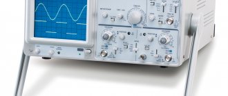
When the relays of the electronic circuit operate, rectangular pulses should be generated on the PWM board and supplied to the optocouplers. This can be checked using an oscilloscope. The correct assembly of the diode bridge of the device also needs to be checked; for this, a voltage of 15 V is applied to it (the current should not exceed 100 mA).
The transformer phases may have been incorrectly connected when assembling the device, which can lead to incorrect operation of the inverter and the generation of strong noise. To prevent this from happening, the correct phase connection must be checked using a dual-beam oscilloscope. One beam of the device is connected to the primary winding, the second to the secondary. The phases of the pulses, if the windings are connected correctly, should be the same.
Using an oscilloscope to diagnose an inverter
The correct manufacturing and connection of the transformer is checked using an oscilloscope and connecting electrical devices with different resistances to the diode bridge. Based on the noise of the transformer and the readings of the oscilloscope, they conclude that it is necessary to improve the electronic circuit of the homemade inverter apparatus.
To check how long you can continuously work on a homemade inverter, you need to start testing it from 10 seconds. If the device’s radiators do not heat up during operation for such a duration, you can increase the period to 20 seconds. If such a time period does not negatively affect the condition of the inverter, you can increase the operating time of the welding machine to 1 minute.
