Transformer
A transformer is a static electromagnetic device having two or more inductively coupled windings on any magnetic circuit and designed to convert, through electromagnetic induction, one or more systems (voltages) of alternating current into one or more other systems (voltages), without changing the frequency.
The transformer performs alternating voltage conversion and/or galvanic isolation in a wide variety of applications - electrical power, electronics and radio engineering.
Structurally, a transformer can consist of one (autotransformer) or several insulated wire or tape windings (coils), covered by a common magnetic flux, wound, as a rule, on a magnetic core (core) of ferromagnetic soft magnetic material.
Under what conditions can current and magnetic flux arise and flow in an electrical circuit?
According to the laws of physics, in order for a magnetic field to form and an electric current to appear in the system, a number of factors must be taken into account that must be implemented. Firstly, magnetic fluxes and electric current can be formed and flow successfully in cases where a closed power circuit has been technically created. Secondly, the created system must contain either magnetic or electrical resistance. And there must also be an external impulse, that same external source of voltage for the created energy circuit. As an addition, we note that inductive reactance indicators are very important for creating conditions for normal operation of the transformer.
Basic principles of transformer operation
The operation of a transformer is based on two basic principles:
- A time-varying electric current creates a time-varying magnetic field (electromagnetism)
- A change in the magnetic flux passing through a winding creates an emf in that winding (electromagnetic induction)
One of the windings, called the primary winding, is supplied with voltage from an external source. The alternating magnetizing current flowing through the primary winding creates an alternating magnetic flux in the magnetic core. As a result of electromagnetic induction, an alternating magnetic flux in the magnetic circuit creates in all windings, including the primary, an induced emf proportional to the first derivative of the magnetic flux, with a sinusoidal current shifted 90° in the opposite direction with respect to the magnetic flux.
Some transformers operating at high or ultra-high frequencies may not have a magnetic core.
The voltage shape in the secondary winding is related to the voltage shape in the primary winding in a rather complex way. Thanks to this complexity, it was possible to create a number of special transformers that can serve as current amplifiers, frequency multipliers, signal generators, etc.
The exception is the power transformer. In the case of the classic AC transformer proposed by P. Yablochkov, it converts the sinusoidal input voltage into the same sinusoidal voltage at the output of the secondary winding.
In the case of a power transformer operating in the Motovilov Converter circuit, it converts the direct power current of the primary winding into the direct power current of the secondary winding with a rectangular alternating voltage on both windings. The latter is rectified into a constant voltage so that constant currents at a constant voltage act at the input and output of the Motovilov circuit.
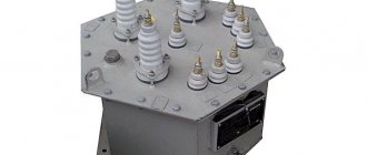
VOLTAGE TRANSFORMER DEVICE
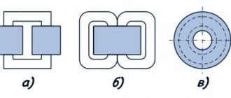
The main components that make up a transformer are the core and windings. Transformer cores are of two types - armored and rod. To work with low-frequency voltages, including 50 Hz, rod magnetic cores are used. In turn, they are divided into:
- W-shaped;
- U-shaped;
- toroidal.
Special transformer iron is used to make the core. Transformer parameters, such as no-load current (TCC) and efficiency, largely depend on the quality of the iron. The core is made of thin sheets of iron, isolated from each other by a layer of oxide or varnish. This is done in order to reduce core losses due to eddy currents.
Both W-shaped and U-shaped cores can be assembled from separate plates, or ready-made halves can be used, made from solid iron strips wound on a special mandrel, glued and cut into two parts - twisted cores. Such cores are called PL.
Each type has its own advantages and disadvantages:
Stacked cores. They are most often used to assemble a magnetic circuit of arbitrary cross-section, which is limited only by the width of the plates. It should be borne in mind that transformers with a core cross-section close to square have the best parameters.
Disadvantages are the need for tight tightening, the increased magnetic field of the transformer dissipation and the low fill factor of the coil window (the actual metal area in the core is less than the geometric dimensions due to the loose fit of the plates).
Twisted. They are even easier to assemble, since the entire core consists of two parts for the U-shaped magnetic core and four for the W-shaped one. The characteristics are much better than those of a type-setting magnetic core. Disadvantages - the contacting surfaces must have a minimum gap to avoid weakening of the magnetic field.
When impacted, the plates of the halves often peel off and are very difficult to align for a tight fit. There is only a certain range of magnetic core sizes.
Toroidal. They are a ring made of transformer iron tape. They have the best characteristics of all types of cores, minimal performance characteristics and an almost complete absence of magnetic dissipation field.
The main disadvantage is the difficulty of winding, especially large-diameter wires.
A classic transformer has one primary winding and one or more secondary windings. The windings are insulated from each other to eliminate the possibility of a breakdown between windings. Both the primary and secondary windings can have taps.
In W-shaped transformers, all windings are wound on the central rod, and in U-shaped transformers, the primary can be placed on one rod, and the secondary on the other. Much more often, the windings are divided in half and wound on both rods. Then both halves of the windings are connected in series.
This winding improves the characteristics of the transformer and reduces the amount of wire for the windings.
Main parts of the transformer design
The main parts of the transformer design are:
- magnetic circuit
- windings
- frame for windings
- insulation
- cooling system
- other elements (for installation, access to winding terminals, transformer protection, etc.)
In practical transformer design, the manufacturer chooses between three different basic concepts:
- Rod
- Armored
- Toroidal
Neither of these concepts affects the performance or operational reliability of the transformer, but there are significant differences in their manufacturing process. Each manufacturer chooses the concept that it considers most convenient from a manufacturing point of view, and strives to apply this concept throughout the entire production volume.
While bar-type windings enclose a core, armor-type core encloses the windings. If you look at the active component (i.e. the core with windings) of the rod type, the windings are clearly visible, but they hide the rods of the core magnetic system behind them. Only the upper and lower yoke of the core are visible. In an armor-type design, the core hides the main part of the windings.
Another difference is that the axis of the rod-type windings, as a rule, has a vertical position, while in an armored structure it can be horizontal or vertical.
Common transformer modes: what options exist
Acceptable technical characteristics of transformers allow units to operate in different conditions. Thus, new equipment that has just been put into operation is undergoing testing. If necessary, then under the supervision of specialists. Sometimes the initial stage of work is called commissioning of equipment. As soon as the first stage is successfully completed, the next and most important one starts - the nominal mode, when the current transformers and their characteristics work for the result, according to the instructions and technical parameters. In case of failures in the system, abnormal operating modes of power equipment may appear, and such conditions include idling, short circuit, which provokes breakdowns and shutdowns in the network, as well as overvoltage, which can disrupt the operation of the well-coordinated mechanism of the electrical main.
Transformer operating modes
Idle mode
This mode is characterized by an open secondary circuit of the transformer, as a result of which no current flows in it. No-load current flows through the primary winding, the main component of which is the reactive magnetizing current. Using the no-load test, you can determine the efficiency of the transformer, the transformation ratio, as well as losses in the core (the so-called “steel losses”).
Load mode
This mode is characterized by the operation of a transformer with a connected source in the primary circuit and a load in the secondary circuit of the transformer. The load current flows in the secondary winding, and the current flows in the primary winding, which can be represented as the sum of the load current (calculated from the ratio of the number of turns of the windings and the secondary current) and the no-load current. This mode is the main operating mode for the transformer.
Short circuit mode
This mode is obtained as a result of short-circuiting the secondary circuit. This is a type of load mode in which the resistance of the secondary winding is the only load. Using the short circuit experiment, it is possible to determine the heating losses of the windings in the transformer circuit (“copper losses”). This phenomenon is taken into account in the equivalent circuit of a real transformer using active resistance.
Idle mode
When the secondary current is equal to zero (no-load mode), the induced emf in the primary winding almost completely compensates for the voltage of the power source, therefore the current flowing through the primary winding is equal to the alternating magnetizing current, there are no load currents. For a transformer with a core made of soft magnetic material (ferromagnetic material, transformer steel), the no-load current characterizes the amount of losses in the core (for eddy currents and hysteresis) and the reactive power of the magnetization reversal of the magnetic core. The power loss can be calculated by multiplying the active component of the no-load current by the voltage supplied to the transformer.
For a transformer without a ferromagnetic core, there are no losses due to magnetization reversal, and the no-load current is determined by the inductance resistance of the primary winding, which is proportional to the frequency of the alternating current and the magnitude of the inductance.
The voltage on the secondary winding is determined to a first approximation by Faraday's law.
Short circuit mode
In short circuit mode, a small alternating voltage is applied to the primary winding of the transformer, and the terminals of the secondary winding are short-circuited. The voltage at the input is set such that the short circuit current is equal to the rated (calculated) current of the transformer. Under such conditions, the magnitude of the short circuit voltage characterizes the losses in the transformer windings, the losses in the ohmic resistance. The power loss can be calculated by multiplying the short circuit voltage by the short circuit current.
This mode is widely used in measuring current transformers.
Load mode
When a load is connected to the secondary winding, a load current appears in the secondary circuit, creating a magnetic flux in the magnetic circuit directed opposite to the magnetic flux created by the primary winding. As a result, the equality of the induced emf and the power source emf is violated in the primary circuit, which leads to an increase in the current in the primary winding until the magnetic flux reaches almost the same value.
The instantaneous magnetic flux in the magnetic circuit of the transformer is determined by the time integral of the instantaneous value of the emf in the primary winding and, in the case of a sinusoidal voltage, is shifted in phase by 90° with respect to the emf. The EMF induced in the secondary windings is proportional to the first derivative of the magnetic flux and for any current shape coincides in phase and shape with the EMF in the primary winding.
What is the difference between a current transformer and a voltage transformer and a power transformer?
There are differences in the operation of CT and.
- The primary current of the CT does not depend on the secondary load, which is typical for VTs. This is determined by the fact that the resistance of the secondary winding of the CT is an order of magnitude less than the resistance of the primary circuit and, in general, the closer it is to zero, the more accurate the device. In voltage transformers and power transformers, the primary current depends on the magnitude of the secondary load current.
- The CT always operates with a closed secondary winding and the value of its secondary load resistance does not change during operation.
- It is not allowed to operate a CT with an open secondary winding; for VT and power transformers, when the secondary winding is opened, a transition to idle operation occurs.
CT accuracy classes
Types of transformers
Power transformer
AC power transformer is a transformer designed to convert electrical energy in electrical networks and in installations intended for receiving and using electrical energy. The word “power” reflects the operation of this type of transformer with high power. The need to use power transformers is due to the different operating voltages of power lines (35-750 kV), city electrical networks (usually 6.10 kV), the voltage supplied to end consumers (0.4 kV, also known as 380/220 V) and the voltage required for the operation of electrical machines and electrical appliances (various from units of volts to hundreds of kilovolts).
A DC power transformer is used to directly convert voltage in DC circuits. The term “power” shows the difference between such transformers and measuring devices of the “DC Transformer” class.
Autotransformer
An autotransformer is a variant of a transformer in which the primary and secondary windings are directly connected, and due to this they have not only an electromagnetic connection, but also an electrical one. The autotransformer winding has several terminals (at least 3), by connecting to which you can obtain different voltages. The advantage of an autotransformer is higher efficiency, since only part of the power is converted - this is especially significant when the input and output voltages differ only slightly.
The disadvantage is the lack of electrical insulation (galvanic isolation) between the primary and secondary circuits. The use of autotransformers is economically justified instead of conventional transformers for connecting effectively grounded networks with voltages of 110 kV and higher with transformation ratios of no more than 3-4. A significant advantage is lower consumption of steel for the core, copper for windings, lower weight and dimensions, and ultimately lower cost.
Current transformer
Current transformer is a transformer powered by a current source. A typical application is to reduce the primary current to a value used in measurement, protection, control and signaling circuits, in addition, the current transformer provides galvanic isolation (different from shunt current measurement circuits). The rated current of the secondary winding is 1A, 5A. The primary winding of the current transformer is connected to the circuit with the measured alternating current, and the measuring instruments are connected to the secondary winding. The current flowing through the secondary winding of a current transformer is equal to the primary winding current divided by the transformation ratio. ATTENTION! The secondary winding of the current transformer must be reliably short-circuited or short-circuited to the low-impedance load of the measuring instrument. If the circuit is accidentally or intentionally broken, a voltage surge occurs, which is dangerous for the insulation, surrounding electrical appliances and the life of technical personnel! Therefore, according to the rules of technical operation, it is necessary to short-circuit unused secondary windings, and all secondary windings of current transformers must be grounded.
Voltage transformer
Voltage transformer - a transformer powered by a voltage source. Typical applications are the conversion of high voltage to low voltage in circuits, measuring circuits and relay protection and automation circuits. The use of a voltage transformer allows you to isolate the logical protection circuits and measurement circuits from the high voltage circuit.
Pulse transformer
A pulse transformer is a transformer designed to convert pulse signals with a pulse duration of up to tens of microseconds with minimal distortion of the pulse shape. The main application is the transmission of a rectangular electrical pulse (maximum steep front and cutoff, relatively constant amplitude). It serves to transform short-term video voltage pulses, usually periodically repeated with a high duty cycle. In most cases, the main requirement for IT is the undistorted transmission of the shape of the transformed voltage pulses; When an IT input is exposed to a voltage of one form or another, it is desirable to obtain a voltage pulse of the same shape at the output, but perhaps of a different amplitude or polarity.
Isolation transformer
An isolation transformer is a transformer whose primary winding is not electrically connected to the secondary windings. Power isolation transformers are designed to improve the safety of electrical networks in case of accidental simultaneous contact with the ground and live parts or non-current parts that may be energized in the event of insulation damage. Signal isolation transformers provide galvanic isolation of electrical circuits.
Matching transformer
Matching transformer is a transformer used to match the resistance of various parts (cascades) of electronic circuits with minimal distortion of the signal shape. At the same time, the matching transformer ensures the creation of galvanic isolation between sections of the circuits.
Peak transformer
Peak transformer is a transformer that converts a sinusoidal voltage into a pulse voltage with a polarity changing every half cycle.
Twin throttle
A dual choke (counter inductive filter) is a transformer with two identical windings. Thanks to the mutual induction of the coils, it is more efficient than a conventional inductor with the same dimensions. Twin chokes are widely used as input filters for power supplies; in differential signal filters of digital lines, as well as in audio technology.
Transfluxor
A transfluxor is a type of transformer used to store information. The main difference from a conventional transformer is the large amount of residual magnetization of the magnetic circuit. In other words, transfluxors can act as memory elements. In addition, transfluxors were often equipped with additional windings that provided initial magnetization and set their operating modes. This feature made it possible (in combination with other elements) to build circuits of controlled generators, comparison elements and artificial neurons on transfluxors.
Transformer condition diagnostics
Damage or deviations from normal operation that occur in power transformers can be caused by design flaws, hidden defects, violations of transportation rules, installation technology, operation, or poor-quality repairs. Timely identification of an emerging defect allows you to take measures to prevent its development and maintain the operating condition of the transformer. The most typical damage to transformers is the following: damage to windings and insulation, active steel, porcelain and internal insulation of inputs, contacts of the voltage regulation device, auxiliary components and devices. Diagnostics of the transformer condition is complex: it is carried out at the transformer manufacturing stage, before putting it into operation and during operation. After completion of installation, before commissioning, tests are carried out to the extent specified by the PUE: determining the conditions for switching on the transformer, measuring the insulation characteristics and direct current resistance of the windings, checking the operation of the switching device and taking a pie chart, testing the tank with radiators with hydraulic pressure, checking the condition of silica gel, phasing transformer, transformer oil test, inrush test for rated voltage. All work on diagnosing transformers during its operation is divided into four groups:
- not requiring touching the operating transformer;
- not requiring disconnection, but associated with the need to touch the transformer or its auxiliary devices;
- performed on a disconnected transformer;
- performed on a transformer taken out for repair.
The first group of works includes periodic external inspections with monitoring of the readings of signaling devices and monitoring and measuring equipment. During periodic inspections the following is checked:
- state of external insulation, i.e. bushing insulators: are there any cracks or chips of porcelain on them, what is the degree of surface contamination, is there corona corrosion observed;
- serviceability of measuring instruments, thermometers, oil indicators, exhaust pipe membrane, gas relay. The window of the latter must be filled with oil;
- presence or absence of oil leakage;
- state of contact connections accessible for observation. Their increased heating can be detected using thermal indicators or by the appearance of the contact and the tire: the appearance of tarnished colors, darkening, burnout of paint, “flowing” air over the contact. Very high heat can cause the contact to glow, especially at night.
Effective heating control is carried out using a thermal imager (a microprocessor device with a display that measures temperature at a distance, without direct contact with the controlled object). At the same time, all control equipment is inspected, based on the readings of which one can judge the occurrence of some kind of malfunction or the danger of its occurrence. The temperature of the upper layers of oil is controlled by a thermometer. If this temperature exceeds the permissible limit, first of all you should pay attention to the health of the cooling system. If no faults are found in it, then the increase in temperature is most likely due to the occurrence of internal damage in the transformer: a turn short circuit in the winding, deterioration in the condition of contact connections, deterioration in oil circulation due to a decrease in the cross-section of the oil channels due to swelling of the insulation or the presence of a foreign object. A decrease in the oil level below the permissible level may be due to leaks in the tank or radiators, deterioration of the oil breathing system through the conservator, or insufficient amount of oil filled. Operating a transformer with a reduced oil level is not allowed, as this can lead to accelerated aging of the oil, activation of the gas relay and shutdown of the transformer, and deterioration of the cooling system. If the level drops so much that the winding insulation is partially in the air, an air flashover may occur with a short circuit between the windings, which is a serious accident. During inspections, other violations of the normal operation of the transformer may be revealed, for example, such as increased hum, most often caused by increased vibration of the transformer or its elements, violation of external contact connections, accompanied by characteristic crackling, failure of fastening of the busbar, deformation of any elements, damage drainage system, etc. Personnel who notice any malfunction in the operation of the transformer during inspection must inform the relevant service of the enterprise about this and take the necessary measures to eliminate the malfunction, if this is possible without shutting down the transformer. If internal damage is detected, the transformer must be turned off by maintenance personnel with prior notification to superior duty personnel. The second group of measures for diagnosing the condition of transformers includes taking oil samples to check its electrical properties, chemical or chromatographic analysis of gases dissolved in the oil. This also includes measuring the vibration of the tank or other parts of the transformer, monitoring partial discharges, sampling gas from a gas relay triggered by a signal, etc. A significant part of the damage to transformers does not appear at all during external inspection, especially if it is incipient internal damage. A significant part of them can be determined by checking the condition of the oil. Internal damage such as local overheating, partial discharges, minor sparking in contacts, etc., to a greater or lesser extent, affect the properties of transformer oil. In addition, a change in the properties of the oil occurs when it is moistened, contaminated, or air or other gas enters it during the natural aging of both the oil itself and the solid insulation. Oil sampling must be done carefully to avoid moisture, oil contamination and interference. Otherwise, the test or oil analysis results will be unreliable. To take an oil sample, it is necessary to clean the drain plug or tap from dirt and dust, drain a certain amount of oil into a foreign container and collect the required sample. The sample container must have a capacity of at least 0.5 liters with a ground-in stopper and pre-washed twice with the oil intended for testing. It must be taken into account that a sharp change in temperature can cause moisture condensation inside the container, so the latter should be opened after it has reached ambient temperature. Currently, chromatographic analysis of gases dissolved in transformer oil has become widespread, and in recent years special attention has been paid to furan compounds. Special techniques have been developed that allow the presence of certain sets of gases with their concentrations to identify various damage to the transformer, including damage to paper insulation, the presence of an electric arc, a short circuit to the frame, etc. The third group of measures for diagnosing the condition of the transformer, carried out with the transformer switched off, includes tests and determination of the insulation condition of windings, magnetic cores, high-voltage bushings, switching devices and auxiliary equipment. This includes all types of preventive tests, audits, etc. The fourth group of activities carried out on a transformer removed for repair involves a more complete analysis of the condition of individual parts in order to determine or clarify the scope of repair work. However, the final decision on the need to take the transformer out for repair is made based on the results of diagnostic measures of the first three groups. The most unreliable elements of transformers are oil-filled bushings and on-load transformer ratio switching devices (OLTC). Experts have recognized that it is advisable to equip power transformers of power centers with condition monitoring systems under operating voltage. Such systems have been developed and offered for use by foreign and domestic companies. At the same time, the spent insulation life can be monitored, the concentration of certain gases can be monitored, the operation of the transformer cooling system can be controlled, the level of partial discharges in the bushings and inside the transformer tank, the level of acoustic discharges, the state of the on-load tap changer, etc. can be monitored. However, the implementation of these systems is hampered by their high cost. Systems for periodic and automated monitoring of the insulation condition of oil-filled bushings under operating voltage (as recommended by the Guiding Documents) are becoming increasingly widespread. Is the insulation complex conductivity module controlled? , or tg? insulation of inputs, or level of partial discharges.
Damage or deviations from normal operation that occur in power transformers can be caused by design flaws, hidden defects, violations of transportation rules, installation technology, operation, or poor-quality repairs. Timely identification of an emerging defect allows you to take measures to prevent its development and maintain the operating condition of the transformer. The most typical damage to transformers is the following: damage to windings and insulation, active steel, porcelain and internal insulation of inputs, contacts of the voltage regulation device, auxiliary components and devices.
terms of Use
CT requires a high degree of reliability with high voltage and power values. This affects the quality of operation and prevention. Routine work is carried out for proper, complete maintenance, repair, testing, and adjustment. Transformers and equipment are located in the place where personnel are constantly on duty. Daily inspection schedules, control and measurement devices check the operating condition of the electrical network and transformers.
Monitor the readings of instrument sensors, measure:
- Temperature.
- Pressure.
- Oil level.
- Degree of desiccant depletion.
- Condition of oil regenerators.
Also read: What is a transformer
Checks for oil leaks in the transformer cage, outdoor switchgear, closed switchgear, mechanical damage in the housing, flange joints (oil, coolant), radiators, fans, pipe sections. The number of operating fans and the oil level in the gas analyzer are monitored at a certain transformer load. For each mode, its own number of operating equipment, parameters of the cooling medium, gas, water, oil are given. In devices with permanent staff duty, inspections are done less frequently: once every 30 days. At least once every ½ year, an inspection of outdoor switchgear, indoor switchgear, indoor switchgear, and transformer points is carried out.
According to the maintenance schedule, during maintenance, oil is added and unsuitable transformer oil is replaced with a new composition. The quality of the oil is determined by chemical laboratory analysis. The PUE, instructions for transformers and equipment provide criteria for oil requirements, visual inspection, and color. In emergency situations or sudden changes in outside air temperature, unscheduled inspections are carried out.
Protection is subject to verification. Once every 365 days for major repairs, the oil is taken for laboratory analysis. The frequency of maintenance of voltage regulation devices of power transformers is associated with checking the contacts of copper and brass for oxidability. They perform preventive maintenance, cleaning, lubrication, reassembly, and tightening with a torque wrench to reduce the transition resistance in the contact assembly.
In order to change the oxide film, 2 times every 365 days the transformers are disconnected from the electricity, their load is removed to 0, the switches are placed in various adjustable positions several times. Methods of changing positions are done during the transitional autumn-winter period until the maximum load is gained.
Transformer protection
The standard type of protection according to the PUE is installed:
- Zero sequence current protection against external ground faults, clause 3.2.63.
- Protection against currents caused by external short circuits, clause 3.2.64.
- Operational acceleration of protection against currents caused by external short circuits with a time delay of 0.5 seconds, clause 3.2.65 (AT substations, ST block generator).
- Gas protection of the additional transformer clause 3.2.71.
- Protection of the on-load tap-changer contact device with a pressure relay, a separate gas relay, clause 3.2.71.
- Differential current protection of low voltage side circuits (AT) clauses 3.2.70 – 3.2.71.
- Differential phase overload protection.
- From internal damage: level + oil pressure, winding temperature, steel core, presence of gases.
CT protection panel: