Electrical causes of fires are one of the most common causes of fires - almost every fifth fire. Are electrical causes of fires always sufficiently justified?
As many years of experience and practice in studying fires have shown, in order for the investigator and investigator to put forward and finally accept a version of the cause of the fire, sometimes it is enough to detect a melted electrical conductor at the site of the fire.
Knowing that a short circuit has a sufficient thermal impulse and is capable of igniting the insulation of live parts and flammable materials located near electrical installations, some experts believe that they have correctly identified the cause of the fire. In the future, they are not interested in the remaining elements and devices for protecting the electrical network of the fire object. This conclusion about the authenticity of the cause of the fire is incorrect.
To objectively solve crimes and to reasonably determine the cause of a fire, it is necessary to conduct a complete and high-quality study of the entire electrical network of the fire site, record fragments of electrical devices found in the fire, and correctly remove the material evidence necessary for instrumental research.
When investigating fires, elements of the electrical network (protection devices, switching devices, sections of cables and wires with copper and aluminum conductors) that have characteristic traces of exposure to a short-circuit arc or temperature destruction must be removed from the fire site as material evidence.
The sequence of actions of persons involved in fire investigations has been repeatedly indicated in the specialized literature. We consider it useful to systematize and repeat them again.
On this topic ▼
Fire in the apartment
Possible reasons and what to do
The possibility of a fire arising from electrical installations must be put forward and worked out in all cases where there was electrical equipment at the fire site. Inspection of electrical installations is quite difficult, so it is advisable to carry it out with the involvement of energy specialists. Moreover, it should be borne in mind that this inspection cannot be limited only to the premises in which the combustion occurred, because To work out versions of the possibility of a fire from electrical equipment, it is necessary to know the state of the entire electrical network, starting from the power source (transformer substation) to the most remote consumers of electricity located at the fire sites.
Versions about the causes of fires associated with the operation of electrical installations are the widest group of causes. This is primarily due to the power supply at manufacturing enterprises, in agriculture and in everyday life, the possibility of failure of electrical products, as well as the low quality of technical maintenance of electrical equipment. It should be noted that the involvement of electrical equipment in fires is often “established” without sufficient grounds. This requires a more in-depth and competent study of all those phenomena that preceded the fire and took place during its process, which are essential in establishing the true cause of the fire when working out the put forward versions of the possible cause of the fire.
It should be borne in mind that almost all ignition sources associated with the operation of electrical installations have a large reserve of thermal energy and are capable of igniting most flammable substances and materials.
Causes of electrical fires include:
- electric arc;
- short circuit;
- overload of electrical circuits;
- higher contact resistance;
- sparking;
- electrical network overvoltage;
- transition of electric current to metal grounded structures of buildings and structures;
- transfer of electric current to low-current electrical lines (radio, telephone, etc.);
- thermal effects of electric heating devices;
- thermal effects of electric incandescent lamps, their emergency mode and melting of bulbs;
- emergency operation of fluorescent lamps.
On this topic ▼
Children's prank with fire
Cause of fire and consequences
To improve the quality of inspection of electrical equipment during a fire, it is advisable to consider in more detail each of the reasons listed above, bearing in mind that the appearance or presence of some of them is provided for by the normal operation of electrical installations. For example, electric arcs occur during electric welding work; sparking occurs in commutator motors, magnetic starters and contactors; the presence of heated or glowing parts is present in heating devices, etc.
You need to know that overvoltage of the electrical network, high transient resistance and overload of the circuit can lead to a short circuit, the occurrence of an electric arc, and vice versa, a short circuit can lead to overload of the electrical network, to sparking, the formation of an electric arc, to the transition of electric current to metal grounded designs, etc.
That is, some emergency modes transform into others that are more dangerous in terms of the possibility of fires.
Let's take a closer look at the above ignition sources.
Electric arc
Electric arc
An electric arc has a very high temperature (1500-4000 °C) and can ignite almost any combustible material, in direct contact with it, as well as through radiant heat. An electric arc is formed as a result of a stable electrical discharge between two metal elements of an electrical installation that have different potentials. In an electric arc, intense ionization of the gas gap occurs, melting and burning of the metal. In addition, there is intense splashing of molten metal particles, which have a large supply of thermal energy, which, falling on flammable materials, can ignite them.
On this topic ▼
First aid for electric shock
A stable electric arc can most often occur during a short circuit in gas pipes or armored cables and much less often in electrical wires. In this case, as the current-carrying core of an electrical conductor, armor, pipe, or other protective shell melts and burns, the arc can move along their surfaces towards the power source, leaving point or distributed penetration along the length. During an electric arc, short-term storage currents flow through the circuits. Therefore, when an electric arc is formed in emergency mode, secondary (side) phenomena characteristic of a short circuit occur in the electrical circuit. In this case, ignition sources often appear not only at the site of arc formation, but also in other places in the electrical circuit, but towards the power source. In cases not provided for by the normal operation of electrical installations, the occurrence of an electric arc most often occurs during a short circuit.
One of the well-known examples of the use of an electric arc in production is electric welding, in which significant currents flow through the conductors and a large amount of thermal energy is released.
The process of electric arc welding is usually accompanied by the occurrence of:
- parts, structures or their individual sections heated to a high temperature or even hot to be welded;
- scattering of relatively large particles of molten metal over considerable distances;
- heating of contact elements and electrical conductors in places of loose connections;
- sparking in places of poor quality connection or connection of electrical wires to the welding machine, welded parts and structures.
Electrical causes of fire
Thoughtless use of electricity both at home and at work, failure to comply with safety regulations can become a fire factor. Connecting an excessive number of devices to the network can lead to overheating of the cable or contacts; poor insulation can cause sparking.
If the automatic defense systems malfunction or there is no control, the fire center expands, covering ever larger areas.
Short circuit
One of the sources of fire is a short circuit that occurs when the insulating layer of cables, wiring, and conductive parts is damaged.
Causes:
1. Worn-out equipment. 2. Failure to comply with the maintenance schedule. 3. Incorrect choice of cable cross-section during installation or design. 4. Incorrect wire connection. 5. Mechanical damage to the cable insulation.
A short circuit can produce a slight spark or a sudden release of a large number of sparks, often accompanied by an increase in temperature at the fault site. The location of fuels and lubricants and other substances susceptible to combustion nearby provokes a high fire hazard.
Voltaic arc
Serious errors during installation and operation of equipment are indicated by the appearance of an electric arc. Its occurrence can result in severe injuries to personnel and a major fire.
An electric arc is a discharge passing from one electrode to another without physical contact, through the environment - air, oil, vacuum. It is characterized by a loud sound, a bright flash of light, and the release of a large amount of thermal energy.
Causes of arcing:
1. High dust content of the atmosphere. 2. Foreign objects on the equipment body. 3. High humidity, as well as water leaks and condensation. 4. Insulation failure resulting from corrosion, high temperature or mechanical damage. 5. Incorrect equipment connection, installation errors.
Electric arcs often cause large fires.
Transition resistance
If the wiring is installed incorrectly at the junction of the wires with contacts or current collectors, the transition resistance may increase.
Reasons for the increase in contact resistance:
1. Replacing the design connection with twisting. 2. Refusal to install specialized lugs and clamps when connecting electrical appliances. 3. Reducing the contact area of electrical installation devices. 4. Using acid to solder wires.
An attempt to reduce the amount of work by violating technology can result in major losses for the organization and personnel injuries.
Overload of power supply circuits
Overloading of electrical circuits occurs during emergency operation of installations, accompanied by an increase in voltage.
Overloading the power grid results in:
1. High voltage supplied to the network. 2. Incomplete short circuit inside system consumers. 3. Greater power of the connected consumer (in comparison with the calculated one). 4. Malfunctions of the equipment in use, leading to item 3 of this list. 5. Excessive number of devices connected to the network.
To avoid such developments, you should not skimp on protection devices.
Network overvoltage
When there is a voltage surge in the supply network, electrical appliances fail and short circuits occur.
Causes of overvoltage:
1. Lightning strike on an electrical installation. 2. Emergency overload, a sharp increase (decrease) in energy consumption in the general network. 3. Transient – occurs when the network is interrupted or damaged. 4. Electrostatic.
To protect against voltage surges in the external network, a transformer and grounding are used.
Order a consultation
Leave your contacts and we will contact you within 5 minutes. Applications are accepted around the clock!
Short circuit
Among the causes of electrical fires, a short circuit is the most common, although it can often be a consequence of some other emergency situation in the electrical circuit.
A short circuit occurs when electrical wires with damaged insulation are connected, wires come into contact with metal grounded structures of buildings and structures, foreign metal objects come into contact with bare wires, or breakdown of charred or broken insulation of wires and other electrical installation products. As a result of a short circuit, due to a sharp increase in current in the electrical circuit, the temperature of the conductors increases significantly, which leads to ignition of the insulation of electrical wires and cables and is most often accompanied by melting of the metal of the conductors.
Overload of electrical circuits
Overload is a phenomenon in which current loads appear in the electrical network, windings of electrical machines, instruments and apparatus that exceed the long-term permissible ones.
The most common causes of overloading electrical circuits are:
- incomplete or non-metallic short circuit through some contact resistance;
- overvoltage in the electrical network;
- operation of a three-phase motor on two phases due to a break in the third or tripping of one of the fuses;
- jamming, overloading of a mechanism driven by an electric motor (for example, a conveyor line motor);
- incorrect choice of electric motor for a given working mechanism (underestimated power in relation to the required);
- jamming of the electric motor shaft due to insufficient lubrication, or destruction of bearings and shaft misalignment;
- inclusion into the electrical network of powerful electricity consumers not provided for in the calculations.
High contact resistance
High transition resistance is the resistance of a section of an electrical circuit at the junction of individual elements (the junction of wires, connecting them to electrical receivers, contact elements, etc.) in which, if they are not executed correctly, the resistance is higher compared to the resistance of the electrical circuit before these areas and after them
Most often, large transient resistances occur in the following cases:
- in places where wires are connected to each other, when instead of soldering, welding, crimping or bolt clamps, twisted wires with aluminum and copper conductors are used;
- in places where wires are connected to switches, electric motors and other devices without special clamps and tips;
- in switches, magnetic starters, switches, plug connectors (sockets, plugs) on contact elements with a decrease in the effort applied to turn on, failure to turn on, burning, etc.;
- at contact points. made using threaded connections in electrical equipment that is subject to vibration during operation, and especially in cases where there are no devices against self-unscrewing;
- at the junctions of wires made by soldering, but with the use of acids in surface preparation, which almost always remain at the soldering site and subsequently cause increased oxidation of the junctions or nearby sections of the wires.
The formation of ignition sources when large transient resistances occur, as a rule, is possible in the bridges of the appearance of transient resistances described above. The direct source of ignition in this case can be:
- elements of electrical installations heated to a high temperature by heat generated by electric current in a place of high transition resistance;
- electrical sparks or particles of molten and hot metal that occur at the site of a “poor” electrical contact.
High contact resistance may cause a short circuit.
Protection measures
It is much easier to prevent a wiring fire in an apartment than to try to recover from the consequences of a fire. Therefore, to prevent wiring fires, certain safety precautions should be observed:
- At the stage of installation or replacement of electrical wiring, it is necessary to provide a margin for the cable cross-section. This will allow you to increase power if you connect any new device without the risk of fire.
- Ensure that wires are insulated from flammable materials using non-flammable gaskets. For example, on wooden walls it is important to use a special corrugated pipe, textolite strip, asbestos plates and other non-combustible materials. A metal strip can only be used if it is grounded through an RCD, since in the event of a fire in the wiring, potential will transfer to the metal.
- When replacing wiring, you should use a copper cable specifically designed for domestic premises. Despite its high cost compared to aluminum wiring, it is much more reliable. And modern insulating materials do not support combustion, which makes it impossible for such wiring to catch fire.
- Do not connect wires inside walls. Such components cannot be detected until a fire occurs. Therefore, all conductors from the box to the consumer, switch or socket must be solid. And at the connection points they must be connected with factory clamps, avoiding twists.
- If there is a connection between aluminum and copper conductors in the house, such a point should be fixed using a brass sleeve or a special terminal clamp. Even the use of a brass gasket and tightening with a bolt does not provide a 100% guarantee, since the gasket is destroyed and oxidized over time due to the flow of electric current.
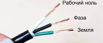
Figure 2: Wire Connection - Do not use shields, cabinets or boxes made of flammable materials. Since in the event of a fire in the same electrical panel, the housing itself will support the combustion. Which will lead to the spread of fire to adjacent elements of the building. If metal distribution panels are used, the fire will not spread beyond its boundaries.
- Use short circuit protection both between cable cores and to ground. It is necessary to select an RCD in such a way that it allows you to de-energize the network in the event of a fault in the wiring or devices, when connecting a load that is too large for wiring, and in other emergency situations.
Figure 3: Connecting machines - Refuse to use faulty devices - if you notice damage to the insulation, unusual noise and other signs, take it for repair. The operation of such devices not only threatens their breakdown, but can also lead to a fire in the wiring.
- When repairing equipment or any elements of the electrical network, turn off the power to the room. Since the cause of a fire is often an artificial short circuit made by a careless repairman during work.
- When leaving home, be sure to turn off the power to each device whose operation is not necessary in your absence. Since the cause of a short circuit and further fire in the wiring can be an unloaded device. And if you are away from the apartment for a long time, it is better to turn off the input machine.
It should be noted that the best way to prevent a fire is a fire alarm. Especially for wooden houses or rooms with flammable finishes. Since it will notify about burning wiring even before the critical spread of the flame. Despite the additional costs, this solution will ensure fire safety for your home.
Sparking
Sparking
Sparking in electrical installations is a very common phenomenon and occurs both during normal operation of individual consumers of electrical energy and in emergency mode. Sparking is formed during contact and arc electric welding, turning switches, magnetic starters, contactors, switches on and off, on rings and commutators of electric motors when brushes do not fit tightly to them, and in places of poor-quality connection of wires to consumers of electrical energy, when individual sections of wires come into contact with each other or with grounded structures, etc. During sparking, ignition sources are formed that have energy and temperature sufficient to ignite many flammable substances and materials.
Sparking in non-flammable and non-explosive environments, as well as in the absence of flammable materials and structures in the immediate vicinity, does not pose a great danger.
What to do in case of a wiring fire?
If the apartment smells of burnt wiring, you notice smoke or an open fire in places where wires run or connect, or on electrical appliances that are turned on, you must take the following measures:
- Turn off the electricity, preferably at the input circuit breaker, in order to ensure a simultaneous break in both phase and zero. Without this, there is a high probability of electric shock in case of fire.
- If possible, protect the source of the fire or localize the fire. Under no circumstances should you touch hot elements to prevent burns.
- If there is a fire, begin to extinguish it.
If for some reason the operating conditions of the electrical wiring do not allow it to be de-energized, then the wiring must be extinguished using special means that do not conduct electric current.
Overvoltage in an electrical circuit
Due to the fact that power supply sources have limited power, connecting or disconnecting electrical consumers from them leads to a change in voltage in the electrical network. To compensate for the decrease in voltage, when a large number of consumers are turned on simultaneously, the voltage of the power supply is increased. Therefore, when most consumers are turned off, the voltage in the electrical network becomes higher than the nominal one (127, 220, 380 V). The magnitude of overvoltage can vary and the differences are most often observed in rural areas.
The cause of overvoltages in the electrical network can also be the failure of the speed controller at local power plants, when, figuratively speaking, the generator engine goes into overdrive. Overvoltage can occur: during short circuits; when “high” voltage enters low-voltage networks; during lightning discharges; electromagnetic induction, etc.
The fire hazard of overvoltage, depending on the specific conditions, may include the following:
- increasing the likelihood of a short circuit;
- increasing the current load in certain sections of the electrical circuit and the possibility of overload;
- increasing heat generation in electric heating devices;
- increasing the likelihood of emergency conditions in incandescent lamps;
- increasing the likelihood of failure of individual elements of household electrical consumers (TVs, radios, power supplies, etc.), as well as industrial electrical equipment.
Transfer of electric current to grounded metal structures
The transition of electric current to metal grounded structures of buildings and structures that have an electrical connection to the ground (roofs, drainpipes, heating and water supply system pipes, metal beams, meshes under a layer of plaster, etc.) occurs as a result of their contact with one of live phase wires. In the event of contact between them, significant duck currents are generated, which can lead to operation of the electrical protection if it is selected correctly. In this case, the danger of electric current passing to metal structures is limited to the point where the wire touches the structure, where significant sparking and a short-term occurrence of an electric arc are possible, which can ignite nearby combustible materials.
On this topic ▼
Lightning protection of buildings, structures, equipment and communications
If there is a transition of electric current to metal structures that do not have good grounding and a sufficiently tight connection of individual parts to each other, then large transition resistances arise along the path of the current, and periodic breakdown of the air gap or constant sparking is possible. In this case, combustion is possible both from heating of metal parts and from sparking. Heating and sparking can be so strong that individual sections of metal structures can melt. With this phenomenon, the leakage current may be insufficient to trigger even the correctly selected protection.
It is characteristic that heating of metal structures and sparking can occur not only in the place where the contact of the electric wire with parts of the building is detected, but in completely other areas where there are no electrical switches, sometimes several hundred meters away from the point of contact. Fires caused by the spread of electric current through the metal structures of buildings are characterized by the possible presence of several sources. In this case, a fire can even occur in different buildings.
The transfer of electric current to metal structures is possible:
- when an overhead power line wire breaks;
- in case of mechanical damage to the insulation of electrical wires laid on metal structures and communications of buildings;
- when using metal structures and communications as a return wire when carrying out electric welding work;
- when using metal structures and building communications as grounding;
- in case of destruction of insulators or damage to the insulation of wires in metal pipe supports at the entrance to buildings, etc.
The transfer of electric current is possible not only to the metal structures of the building, but also to other electrical networks. If this transition occurs in low-current lines, it can lead to their ignition and fire. Such a transition is possible in places where lines of different voltages are laid together, upon contact or intersection, if the insulation in them is damaged.
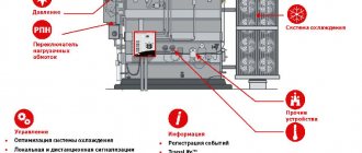
Causes of transformer fires.
Overheating from short circuits in windings as a result of interturn insulation breakdown:
- in one winding with increased voltage;
— at the site of microcrack formation as a manufacturing defect;
- from aging;
— from exposure to moisture or aggressive environments;
— from the effects of local external or internal overheating;
- from mechanical damage.
Overheating from short circuits to the housing as a result of breakdown of the electrical insulation of the windings:
- increased voltage;
— from aging of electrical insulation;
— breakdown of the electrical insulation of the windings to the housing due to mechanical damage to the electrical insulation;
— from exposure to moisture or aggressive environments;
- from external or internal overheating.
Overheating from current overload resulting from:
— long-term continuous operation under maximum load;
— violations of ventilation (cooling);
- increased frequency of switching on and off under load.
In the event of a short circuit, as a result of the impact of an electric arc on transformer oil and its decomposition into flammable gases, explosions can occur, which lead to the destruction of transformers and the spreading of burning oil.
Each power plant has a stock of dielectric means and places for grounding fire equipment. Grounding conductors are made from flexible copper wires.
The supply of any foam when extinguishing electrical installations under voltage is strictly prohibited.
Powder fire extinguishers are used to extinguish electrical fires. installations under voltage up to 1000 V, carbon dioxide up to 10,000 V. In this case, the distance must be at least 1 meter.
Extinguishing fires in electrical installations under voltage in all cases must be carried out in compliance with the mandatory conditions:
— reliable grounding of hand barrels and pumps of fire trucks;
— use of dielectric means by personnel;
- maintaining minimum safe distances from live electrical installations to firefighters working with a barrel or fire extinguisher (when extinguishing with powder, if 1 kV - 1.5 meters, up to 10 kV - 2 meters;
— use water in the form of compact jets from RS-50, RSK-50 barrels and sprayed from barrels with NRT-5 nozzles, as well as non-flammable gases and powder compositions.
In case of fire it is possible:
— rapid spread of fire when the oil system of the generator, transformers is damaged, spreading of flammable oil into cable tunnels, lower floors and basements, as well as along burning insulation and structural elements of the building into adjacent rooms;
— burning of insulation of electrical cables laid in ducts, tunnels and shafts, releasing toxic combustion products;
— combustion of liquid metal coolant (sodium, potassium), which interacts with all chemicals, including water, with intense release of hydrogen, heat, smoke and toxic gases;
— the emergence of dangerous levels of radiation;
— formation of explosive concentrations when the hydrogen cooling system is destroyed;
— rapid and hidden spread of fire along the polymer insulation inside wall and roof panels, releasing large amounts of smoke and toxic combustion products;
— the formation of new fires inside the building from the flowing burning melt of polymer insulation and bitumen;
— deformation and threat of collapse of load-bearing trusses, other unprotected metal structural elements, and coatings;
— the presence of a significant amount of energized equipment;
— disruption of stable radio communication.
When extinguishing fires you must:
— establish contact with the person responsible for the shift of the energy facility, obtain from him information about the situation during the fire and written permission to extinguish;
— find out the grounding locations of fire equipment and trunks, the presence of grounding devices;
— eliminate, first of all, fires that pose an increased danger to load-bearing structures, explosive and fire-hazardous equipment;
— establish areas and premises where it is possible and impossible for personnel involved in extinguishing to stay;
— identify equipment whose operation will contribute to the development of a fire and electrical installations that pose a danger during fire extinguishing.
- supply fire extinguishing agents to electrical installations only after removing the voltage, grounding fire trucks and trunks, and appropriate instructions to senior technical personnel;
— do not allow the State Fire Service personnel to act independently to cut off electricity and the supply of fire extinguishing agents;
— organize, together with the personnel, in the event of a threat of fire spread, stopping the turbogenerators and displacing hydrogen with inert gas from the cooling system, draining the oil from the oil system and oil tanks into an emergency container;
— supply powder, low expansion foam or sprayed water inside transformers and other oil-filled equipment through openings;
— prevent the accumulation of State Fire Service personnel in rooms with electrical installations.
Burning transformers are turned off on all sides and grounded. In case of developed fires, protection from high temperatures of neighboring transformers, reactors, equipment and installations is organized. Fires of transformers, reactors and oil switches are extinguished with medium-power foam with a foaming solution supply rate of 0.2 l/(m2s), and with finely sprayed water with an intensity of 0.1 l/(m2s). During the reconnaissance process, the nature of damage to transformers, reactors and pipelines containing transformer oil, the direction of spreading of burning liquid towards adjacent transformers and other equipment, the danger of explosion of expansion tanks, the presence of stationary foam or water fire extinguishing installations and, if necessary, the possibility of putting them into operation are identified. .
If the oil is burning above the transformer cover and the oil tank below it is not damaged, then one or two hand-held water nozzles with G-5 nozzles are used to extinguish the fire, which ensure optimal water flow at a flow rate of 0.2-0.24 l/(m2s) . If the expansion tank on a transformer is on fire, a portion of the oil equal to its volume (approximately 10% of the transformer oil volume) is drained into an emergency container. It is prohibited to drain any more oil from the transformer (reactor), because This can damage the internal windings and aggravate the fire.
If the transformer cover is torn off during a fire, oil may burn in the tank and around the transformer. In this case, first eliminate the burning of oil around the transformer with sprayed water, medium-expansion air-kinetic foam, or in combination with a spray jet and fire extinguishing powders at the same time. If oil extinguishing is carried out using sprayed jets, it is advisable to place the barrels evenly around the perimeter of the fire (Fig. 9.2), and when extinguishing with foam or a combined method, fire extinguishing agents are supplied in an accompanying air flow. This is the most effective technique, ensuring the flow of powder and sprayed water into the combustion zone at the same time. Extinguishing oil in a tank when the roof is torn off is carried out with medium expansion foam, which is supplied using foam lifters or retractable ladders.
Rice. 9.2. Scheme for supplying sprayed water and fire extinguishing powder to the combustion zone
When oil tanks, pipelines are destroyed or oil is released, it spreads throughout the area. To prevent the spreading of burning oil during extinguishing, barrier shafts of earth or sand are created, or diversion channels are created taking into account the terrain. At the same time, prepare the required amount of forces and means to extinguish the burning transformer, and to cool the tanks of neighboring transformers, as soon as they are ready, water jets are introduced with an intensity of 0.5-1 l/s per 1 m of the perimeter of the transformer tank. During the extinguishing process, the RTP should not allow fire to spread through ventilation ducts; in the premises of transformer and distribution devices, take measures to protect control panels. When feeding barrels, avoid getting water on the heated porcelain parts of the apparatus, insulators and arresters.
Thermal effects and emergency operation of incandescent lamps
Incandescent lamp device
The main causes of fires from incandescent electric lamps are:
- direct contact of flammable materials with the heated lamp bulb;
- the effect of thermal radiation from a lamp on combustible materials;
- emission of hot drops of a spiral formed under the influence of an arc between the electrodes or one of the electrodes and a burnt filament;
- contact of heated particles of the spiral with flammable materials as a result of an explosion of the bulb of an incandescent lamp.
Fires caused by incandescent lamps can be caused by:
- violation of the rules for operating incandescent lamps, for example, using them in fire hazardous areas without protective glass covers;
- non-compliance with the minimum permissible distances from incandescent lamps to flammable and combustible materials, the use of paper lampshades, etc.;
- poor-quality energy supply (sharp fluctuations in voltage in the electrical network, which can lead to an arc or explosion of the bulb).
The degree of heating of the bulbs of electric incandescent lamps depends on the distance from the filament to the bulb and on the power of the lamp. However, lower power lamps with small bulb sizes may have a higher temperature on the surface of the bulbs than larger, more powerful lamps. For industrially produced incandescent lamps with a power of 40 to 100 W, under normal operating conditions, the temperature on the surface of the bulb is in the range of 125-240 °C. But if heat accumulates (for example, contact with any materials), it can increase by several hundred degrees and lead to the ignition of flammable materials. For example, a 100 W incandescent lamp wrapped in cotton cloth takes just 5 minutes. may have a temperature on the surface of the flask of 350 ° C and lead to fire of the fabric.
Studies have shown that cotton, cotton wool and products made from them, located at a distance of up to 30 mm from the bulb of an incandescent lamp, can ignite within one hour.
An emergency mode in incandescent lamps and, as a result, rupture of the bulbs, the occurrence of an arc, melting of the electrodes and penetration of the lamp bulbs by drops of molten metal is possible with a significant increase in voltage in the electrical network, as well as due to the low quality of incandescent lamps (design and technological factors, for example, poor contact at the connecting a tungsten filament to a nickel electrode).
If the bulb of an incandescent lamp is destroyed, hot particles of the spiral may fall out and fall on flammable materials. When an electric arc is formed inside the bulb of an incandescent lamp, the contact of hot metal particles with combustible materials is possible not only when the lamp bulb is destroyed, but also when it is penetrated by molten metal particles. Studies have shown that when nickel electrodes are melted, drops of metal in 50% of cases melt through the bulb of an incandescent lamp, leaving holes with a diameter of 1 to 3 mm. When hot drops of nickel exit the bulb of an incandescent lamp into the atmosphere, they explode, forming a stream of approximately 4,000 particles. The temperature of nickel particles ranging in size from 0.5 to 3 mm is in the range of 1500-2200 °C, which represents a high fire hazard.
Lecture “Causes of fires in electrical installations and their prevention”
9 LECTURE “CAUSES OF FIRE IN ELECTRICAL INSTALLATIONS AND THEIR PREVENTION”
9.1 Characteristics of causes
When operating machines, installations and electrical networks, their fire hazard lies in the manifestation of the thermal and spark action of electric current in conditions favorable for the ignition of combustible materials. Combustible materials in electrical installations are solid and liquid (transformer oil) insulating materials, which represent a significant amount in electrical machines, devices and networks. The most common causes of fires in electrical installations are: wire overload, short circuit, high transient resistance in electrical networks, electric arc or sparking.
Overloading of wires occurs when a larger current passes through them than is allowed by the load conditions. The main reason for overload in the electrical network is the parallel connection of an excessive number of current consumers to it.
A short circuit is the connection of opposite live wires through a very low resistance. In a three-phase system, three main types of short circuits are possible: three-phase - when 3 phases are connected to each other, two-phase - when 2 phases are connected to each other without contact with the ground and, single-phase - when 1 phase is connected to a solidly grounded neutral
The connection of one conductor to ground in isolated neutral systems is called an earth fault. The main causes of a short circuit include: damage to the insulation of the wires, contact with non-insulated wires by conductive objects, exposure of the wires to chemically active substances, dust and dampness, improper installation of the electrical network, etc. A short circuit can occur directly in electrical machines and installations.
Protecting the electrical network from overload and short circuit using fuses is only effective if they are correctly selected. More reliable in this case are automatic installation machines, in which, during overloads, thermal protection is triggered due to deformation of the bimetallic plate from heating while a current exceeding the rated current passes through it.
The cause of local heating of wires and fires can also be the transition resistance that occurs at the places where cables or wires are connected to each other or at the places where they are connected to electrical machines and devices. Transition resistances arise from poor contacts at the connection points, as well as from oxidation of the connection points or loose fit to the terminals and contacts of electrical appliances. Splicing of wires must be done using welding, screw clamps, lugs and crimping, while avoiding unsoldered (cold) twists of wires. Reducing contact oxidation is achieved by using sliding contacts or replacing them with silver ones.
Electric arcs and sparks also pose a fire hazard. An electric arc is a flow of electrical charges passing through an ionized air stream; in this case, the temperature can reach 3000 ° C or more. Sparks and electric arcs ignite insulation, settled dust, fibers, and an explosion of vapors, dust and gas can occur.
The occurrence of sparks and electric arcs can be prevented by proper installation and operation of electrical installations. The importance of this requirement is especially great when choosing electrical equipment for explosive, fire hazardous, particularly damp, chemically active environments and other premises.
According to the “Rules for the Construction of Electrical Installations,” premises and outdoor installations, depending on the propensity to ignite the materials and substances contained in them, as well as from the point of view of the requirements for electrical equipment, are divided into fire hazardous and explosive.
9.2.1 Fire hazardous premises and outdoor installations are divided into 4 classes: P-I, P-II, P-II a and P-III.
Class P-I includes premises in which liquids with a vapor flash point above 45° are used or stored (mineral oil warehouses, pumping stations for pumping flammable liquids, etc.).
Class P-II includes rooms in which flammable dusts or fibers are emitted that become suspended, but cannot, for various reasons, form explosive mixtures with air (woodworking shops, low-dust rooms of mills, etc.).
Class P - IIa includes premises containing solid or fibrous flammable substances (paper warehouses, assembly shops of furniture factories, etc.).
Class P-III includes outdoor installations in which flammable liquids with a flash point of vapor above 45° and solid flammable substances are used or stored (open warehouses for mineral oils, loading and unloading racks for flammable liquids, etc.).
9.2.2 Explosive premises and outdoor installations are divided into six classes: BI, B-Ia, B-Ib, V-1d, V-II, V-II a.
Class BI includes premises in which, under normal short-term operating conditions, flammable vapors or gases are released in such quantities and have such properties that they can form explosive mixtures with air or another oxidizer (filling rooms for flammable liquids, filling stations for cylinders with flammable gases and etc.).
Class B-la includes premises in which explosive mixtures of flammable gases and vapors with air or other oxidizer can only form during accidents or malfunctions (rooms of gas turbines, warehouses of flammable gas cylinders, etc.).
Class B-Ib includes the same premises as class B-1a, but differing in one of the following features: flammable gases in these premises have a high lower explosive limit (15% or more)); in case of accidents, a general explosive concentration is not formed, but only a local one is possible (for example, rooms for the electrolysis of water and table salt); flammable gases, flammable and combustible liquids are present in small quantities that do not create a total explosive concentration, and work with them is carried out without the use of open flame.
Class B-1g includes outdoor installations containing explosive gases, vapors, flammable and flammable liquids (gas tanks, unloading racks for flammable liquids, etc.). Premises in which flammable dust or fibers are released into suspension and, when loading and unloading technological equipment, capable of forming explosive mixtures with air or another oxidizer, belong to class B-II.
Class B-IIa includes premises in which the formation of explosive mixtures of flammable dusts or fibers with air is possible only as a result of an accident or malfunction (premises for the preparation and packaging of crushed dried coal, peat, grinding departments of mills, flour warehouses, etc.).
Determining the fire and explosion hazard class of a room or outdoor installation is very important, because the selection of general industrial or explosion-proof electrical equipment depends on it.
9.2.3 Explosion-proof electrical equipment includes devices that ensure the safety of its use in hazardous areas and outdoor installations.
Explosion-proof electrical equipment is divided into explosion-proof, increased reliability against explosion, oil-filled, purged (under excess air pressure), spark-proof and special.
Explosion-proof is electrical equipment whose shells can withstand the maximum pressure of an internal explosion of gases, vapors or dust without damaging the shells or spreading flame through gaps or openings into the environment.
High-reliability electrical equipment allows the possibility of transmitting an explosion that occurs inside the shell to the environment, so its explosion protection is ensured by reliable insulation against foreign objects getting inside the shell, and the sparking parts are enclosed in an explosion-proof shell.
In oil-filled electrical equipment, all normally sparking parts are immersed in oil, thereby eliminating the possibility of their contact with an explosive environment.
Inside the enclosures of purged electrical equipment, excess pressure is constantly maintained, preventing the ingress of explosive mixtures from the environment into them.
Intrinsically safe is electrical equipment, the sparks and heating of parts of which, in terms of thermal energy reserves, are insufficient to ignite an explosive environment.
Lamps pose no less of a fire hazard than machinery and electrical equipment. A lamp is an electric lamp complete with lighting fixtures. Electric lamps can be fluorescent, in which the temperature on the surface of the discharge tubes usually does not exceed 40-50°, incandescent lamps, the temperature on the surface of the bulbs of which reaches 500° or more, and arc lamps with an electric arc temperature of 3000-4000°.
Due to their widespread use and high fire hazard, incandescent lamps are often the cause of fire, which in many cases is associated with the quality of the lamps. From the point of view of security, luminaires are divided into open (the lamp and socket are not separated from the environment), protected (the lamp and socket are closed with a glass cover), waterproof (the design of which prevents the penetration of moisture into the wires and the lamp), dustproof (preventing dust from penetrating into the cavity of the lamp) and explosion-proof (the use of which is allowed in an explosive environment). According to their design, explosion-proof lamps are divided into explosion-proof, increased reliability and special.
Fire safety measures in electric lighting include the correct choice of types of lamps depending on the conditions in which they are used. Only protected lamps should be installed in warehouse fire hazardous areas. The fastening of lamps must be reliable. The use of paper lampshades and the placement of electric lamps near combustible materials is not allowed.
When designing intra-shop power lighting networks, wires and cables are selected according to permissible current loads, voltage losses and heating. For bare wires, when laying them inside buildings, the maximum long-term permissible temperature is 70°, and for wires and cables with rubber insulation, the permissible core temperature is 65°. For cables with impregnated paper insulation, the operating temperature depends on the voltage and number of cores and ranges from 50 to 80°.
Emergency operation of fluorescent lamps
Fluorescent lamp
Fire safety of fluorescent lamps means the practical impossibility of fire, both the lamp itself and its environment, which must be ensured by the design of the lamp, the choice of components and materials with temperature characteristics corresponding to the thermal operating conditions of the lamp. In this case, fire safety characteristics are the compliance of the temperature on the main elements of the lighting device with acceptable values, both in operating and emergency modes of its operation.
Let's consider the possible reasons for the appearance of high temperatures on fluorescent lamps with standard electromagnetic ballasts (ballasts). From the point of view of the physical process of producing light, fluorescent lamps convert a larger portion of electricity into visible light radiation than incandescent lamps. However, under certain conditions associated with malfunctions of the ballasts of fluorescent lamps, their strong heating is possible (in some cases up to 190-200 ° C), resulting in softening and leakage of the filling compound, leading to the ignition of the polymer diffusers of the fluorescent lamp.
Starters pose a certain fire hazard, because... inside some of them there are flammable materials (paper capacitor, cardboard gaskets, etc.).
An example of a fire caused by emergency operation of a fluorescent lamp control gear is a fire that occurred on March 26, 2012 in kindergarten No. 262 of OJSC Omsk. As a result of the emergency operation of the control gear, the diffuser of the light device caught fire, it collapsed onto the floor and the subsequent fire of the floor covering.