Why is zero needed in electricity?
Zero completes the electrical circuit. Without this wire, there can be no electric current in the circuit, which provides the power to power household appliances. Essentially, the neutral wire is ground.
Where does zero come from in the electrical network?
The zero originates from the complete 6(10)/0.4 kV transformer substation, where the transformer is connected to the ground loop by its zero bus. Initially, it is the earth that is a conductor with zero potential, and this is why many people confuse zero with earth. The overhead power line (overhead power line), leaving the transformer substation, has 4 wires - 3 phases and a neutral, which at the beginning of the line is connected to the neutral of the transformer. Along the overhead line, re-grounding is carried out through one support, which additionally connects the zero of the line to the ground, which provides a more complete connection of the “phase-zero” circuit so that the end consumer has at least 220V in the outlet.
Why is zero needed?
The main purpose of the neutral wire is to close the circuit to create electric current for the operation of any electrical appliance. After all, in order for current to appear, a potential difference between the two wires is necessary. This is why it is called zero because the potential on it is zero. Hence the voltage level is 220V - 230V.
Method for determining zero and grounding
When working with neutralized electrical parts, the question often arises of how to determine zero and grounding. There is a special technique for this, the principle of which we explain to readers in accessible language. We immediately draw the attention of beginners, if you need to install the device at home, you need to determine zero, phase and grounding at the mounting location.
There is the simplest method by which grounding is determined - this is the use of color markings, however, this method is not always reliable.
- Let's start the technique using a special lamp. But first, let's put it together into a single whole;
- We take a regular socket and screw a suitable incandescent lamp into it;
- We attach the wires to the socket terminal and remove their ends from the insulating layer using a stripper;
- Now we alternately connect the lamp wires with identifiable conductors; if the light bulb lights up, it means you have found the phase. In the situation with two-core cables, the situation is much simpler; it is important for you to find only the phase, when found, the light bulb lights up, therefore, the remaining conductor is the neutral.
Important! If an RCD or automatic circuit breaker is connected to your network and the lamp does not light up during the test, then you have found zero and ground.
What happens when the zero in the leash breaks?
Technical features
In this system, where a common midpoint is used, in addition to the phase-to-phase voltage, there is also a phase-to-phase voltage. The latter is formed between the working zero and the linear wires. The difference between the first and the second is clearly demonstrated below.
Difference between phase and line voltage
The potential difference UF1, UF2 and UF3 is usually called phase, and the values UL1, UL2 and UL3 are called linear or interphase. It is characteristic that UL exceeds UF by approximately 1.72 times.
In an ideally balanced three-phase electric current network, the following relationships must be maintained:
UF1= UF2=UF3;
UL1=UL2=UL3.
In practice, it is impossible to achieve such a result for a number of reasons, for example due to uneven load, leakage currents, poor insulation of phase conductors, etc. When the neutral is grounded, the imbalance of the linear and phase characteristics of the power system is significantly reduced, that is, the working zero allows potentials to be equalized.
Designation
According to GOST 33542-2015 [5], the alphanumeric identification of a linear conductor should begin with the letter “L”, adding after this letter:
- for AC electrical circuits - the sequential number of the linear conductor, starting with the number “1”;
- for DC electrical circuits - the “+” sign for a positive linear conductor and the “-” sign for a negative linear conductor.
The diagram below, as an example, shows linear conductors L1, L2, L3.
Power Distribution System (TN-CS)
Rules for marking live parts according to the PUE
To ensure clarity, simplicity and ease of recognition of individual parts of the electrical network, in accordance with clause 1.1.30 of the PUE, all electrical installations must have an alphanumeric and color designation. Moreover, the presence of one of these designations does not eliminate the need for the other.
And the only relaxation is the possibility of applying a designation not along the entire length of the conductor, but only at the connection points, as shown in the video.
Wire color coding
Marking wires by color is the most visual and allows you to quickly determine the purpose of any wire. This marking can be done by selecting wires with the appropriate core insulation color, by applying paint to the busbars, or by painting or applying special colored tape at the core junctions.
Moreover, the paint on the tires may not be applied along the entire length, but only at the connection points or at the ends of the tires.
Designation of phase wires
So:
- If we talk about the color designation of wires and cables, then we should start with the phase conductors. According to clause 1.1.30 of the PUE in a three-phase network, phase conductors must be marked in yellow, green and red. This is how phases A, B and C are designated respectively.
- The instructions for a single-phase electrical network suggest the designation of the phase wire in accordance with the color of which it is a continuation. That is, if a phase conductor is connected to phase “B” of a three-phase network, then it should be green.
- As for the neutral conductors, they should be blue in color. Moreover, the color of the neutral core does not depend on the three-phase, two-phase or single-phase network in front of you. It is always indicated in blue.
- Wire markings with a yellow-green stripe indicate a protective conductor. It is connected to the housing of electrical appliances and provides safety from electric shock if the insulation of electrical equipment is damaged.
Designation of neutral and protective conductors
- If the neutral and protective conductors are combined, then according to clause 1.1.29 of the PUE, such a wire core should have a blue color with yellow-green stripes at its ends. To make such markings with your own hands, you just need to take a blue wire and mark it with paint on its end seals or use colored electrical tape for this.
- As for DC networks, the positive core of a wire or bus should be indicated in red, and the negative core in blue. In this case, the designation of the neutral and protective conductors corresponds to the markings in alternating current networks.
Letter marking of wires
But color marking of wires is not always convenient. In switchboards, switchgears and on diagrams, the letter designation is much more convenient. It must be used in conjunction with the color designation.
So:
The letter marking of phase wires in a three-phase network corresponds to their colloquial designation - phase “A”, “B” and “C”. For a single-phase network it should be the same, but this is not always convenient. Moreover, it is not always possible to reliably determine which phase exactly. Therefore, the designation “L” is often used.
- If the wires are marked in the panel, then the symbol “N” indicates the neutral wire.
- The letter designation “PE” is used to designate the protective conductor. In addition, the grounding sign is often used, but the fact is that it cannot always accurately indicate the network diagram.
The photo shows a grounding sign
- The fact is that you may come across the designation “PEN”. It denotes the combination of the neutral and protective conductors. This is possible in TN-CS systems, which we discussed in one of our previous articles.
- But the marking of DC electrical wires is carried out with the symbolisms “+” and “―”. Which respectively means positive and negative wire. For direct current there is another difference. The zero core is designated by the symbol “M”, which is sometimes misleading.
DC marking
Re-grounding the neutral wire
Repeated grounding – grounding that is repeated along the entire length of the neutral cable. If you re-ground the neutral protective conductor of the circuit, then the likelihood of an electric shock resulting from the separation of the neutral cable and the connection of the phase to the body after the place where the break occurred is reduced, but it will not completely eliminate the danger, i.e. it will not lead to the same safety conditions that existed before the breakup.
Why is PE protective conductor needed?
A protective conductor or PE is necessary for additional protection of the home. In the event of a short circuit, it diverts current from the location where the wiring is damaged, thereby protecting people from electric shock and property from fire.
In such a network, the load is distributed evenly, since each floor of an apartment building is wired in phases.
The electrical system connected to residential premises is a “star”, which repeats all the vector characteristics of the transformer substation.
Such a system is reliable and optimal, but it also has its drawbacks, since malfunctions periodically occur. Most often, power outages are associated with poor quality wires, as well as poor-quality connections.
What is grounding and neutral wire
First of all, let's figure out what a neutral wire is and what a protective wire is, what are their differences and what is their purpose? Based on this, it will be easier for us to understand the rules for connecting them and the requirements that the PUE imposes on them.
What is a neutral wire
First of all, let's focus on the neutral wire, or as it is also called the neutral wire. According to clause 1.7.35 of the PUE, it is intended to power electrical receivers and is connected to the solidly grounded neutral of the transformer.
- If we speak in simple language and discard some nuances that are not so important for us, then the neutral wire is a conductor connected to the grounded part of the transformer or generator from which you receive power.
- In a single-phase network, which is used in almost all private households and apartments, a phase and neutral wire is required for the operation of electrical installations. The neutral wire is essentially directly connected to ground and ideally has zero potential. That is, there is no voltage on it.
What is grounding?
Grounding or protective conductor in accordance with clause 1.7.34 of the PUE is intended exclusively for electrical safety purposes. Under normal conditions, it is not energized and acts as a conductor only in cases of failure of the insulation of the phase or neutral conductor. At the same time, at the electrical installation itself, it reduces the potential to bladeless.
- In simple terms, grounding is necessary only in case of breakdown. For example, you have a breakdown in the insulation of your washing machine. If it is not grounded, then touching it is equivalent to touching a phase wire. If it is grounded, then nothing will happen, since the excess potential will go into the ground through grounding.
- Grounding can be done using different schemes depending on your capabilities and the power supply circuit. We will consider this issue below.
- The protective conductor in the diagrams is usually designated by the symbols “PE”. The conductor itself should be made of yellow-green wire.
- On some diagrams you may see the designation “PEN”. This means the combination of the neutral and protective wires. We'll talk about it a little lower. The color of such a wire, according to clause 1.1.29 of the PUE, should be blue with yellow-green stripes at the ends.
What is a neutral wire?
When working with electricity, the neutral wire requires special attention. What this is is not always known to people who are not professionally involved with electrical networks, and they often have the erroneous misconception that the neutral cable is only grounding. In fact, the neutral conductor connects the neutrals of installations in three-phase circuits. When a different load is applied to each phase of the three, a neutral shift appears, causing a violation of the voltage symmetry, that is, a violation of the load symmetry leads to the fact that some consumers will receive a reduced voltage, while others will receive an increased one.
If it is lowered, the connected electrical equipment begins to work incorrectly, and if it is greatly increased, any electronics will break down from overload and a fire may occur. Equalization provides a balance between overvoltage and undervoltage. This is the role of the neutral wire in an electrical circuit.
How to determine if the wires are connected correctly
When trying to install an additional socket, connect a chandelier, or household appliances, you need to know which wire is phase, which is neutral, and which is grounding
If the connection is incorrect, the equipment will fail, and careless touching of live wires can end sadly
You need to make sure that the colors of the wires - ground, phase, zero - match their wiring
The easiest way to navigate is by color coding of the wires. But things are not always simple. Firstly, in old houses the wiring is usually monochromatic - two or three white or black wires stick out. In this case, you need to understand it specifically, and then hang tags or leave colored marks. Secondly, even if the conductors in the cable are painted in different colors, and you can visually find the neutral and ground, you need to check the correctness of your assumptions. It happens that during installation the colors are mixed up. Therefore, first we double-check the correctness of the assumptions, then we begin work.
To check, you will need special tools or measuring instruments:
- indicator screwdriver;
- multimeter or tester.
You can find the phase wire using an indicator screwdriver; to determine zero and neutral, you will need a tester or multimeter.
Checking with indicator
Indicator screwdrivers come in several types. There are models on which the LED lights up when a metal part touches live parts. In other models, checking requires an additional button press. In any case, when voltage is present, the LED lights up.
Using an indicator screwdriver you can find the phases. We touch the exposed conductor with the metal part (press the button if necessary) and see if the LED lights up. Lit - this is a phase. Does not light - neutral or ground.
We work carefully, with one hand. Second, we don’t touch walls or metal objects (pipes, for example). If the wires in the cable you are testing are long and flexible, you can hold the insulation with your other hand (stay away from bare ends).
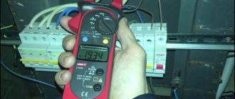
Checking with a multimeter or tester
We set the scale on the device, which is slightly higher than the expected voltage in the network, and connect the probes. If we call a household single-phase 220V network, set the switch to the 250V position. With one probe we touch the exposed part of the phase wire, with the second - to the supposed neutral (blue). If at the same time the arrow on the device deviates (remember its position) or a number close to 220 V lights up on the indicator. We perform the same operation with the second conductor - which is identified by its color as “ground”. If everything is correct, the readings of the device should be lower - less than those that were before.
If there is no color marking of the wires, you will have to go through all the pairs, determining the purpose of the conductors according to the indications. We use the same rule: when testing a phase-ground pair, the readings are lower than when testing a phase-zero pair.
Electric current is especially dangerous for humans, and it is also invisible. When installing wiring, wires of different colors are used for safe and fast work; letters and numbers indicate the wire cross-section. Color and symbol designations or, in other words, markings are prescribed in the standards; you should not violate them so as not to endanger your own and others’ lives.
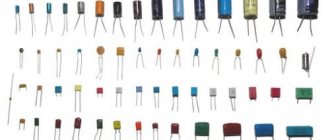
Color coding of core insulation
Visually, the wires differ from each other not only in color and diameter, but also in the number and type of cores. Depending on this characteristic, single-core and multi-core electrical wires are distinguished. Their variety finds its application in alternating current circuits, both in industrial three-phase networks with a voltage of 380V, and in a home single-phase network of 220V. DC power circuits use the same standard of electrical wiring.
What is the phase characterized by?
A phase is a live wire. This conductor is located relative to another, called zero. The rationale for determining the phase is the peculiarity of the substation design. The alternating current generated by them has the same frequency of 50 Hz. At the same time, the emfs are shifted relative to each other in time by a certain phase angle.
The first figure schematically shows the power supply system of a standard residential property with three phases and one neutral conductor. The second image demonstrates the features of connecting electricity to the apartment from a transformer. The consumer in the form of an electrical appliance is designated as Rн. In this case, two wires come out of the transformer in the form of a phase and a zero, to which the ZML grounding is connected. The third figure shows how clearly the installation of power supply is carried out in the absence of a neutral grounded wire connected to the apartment. Grounding in this situation is located directly in the living space.
The concept of phase follows from the definition of electricity. The nature of the formation and flow of alternating current allows us to understand the nature and purpose of the phase wire. Alternating current differs from direct current in value and direction; it can be observed in sockets and direct connections to electrical panels. Main characteristics of alternating current:
- voltage;
- frequency.
Single-phase current is an alternating current obtained through the rotational movement of a conductor or system of conductors under magnetic flux conditions. The wires can be combined in one coil. In order to transmit electricity, two wires are used, including phase and neutral. The voltage between the conductors is 220 Volts. There are two ways to connect single-phase current to a consumer:
- two-wire;
- three-wire.
In the first case, two conductors are used, one of which carries phase current, and the second is zero. This is an outdated power supply scheme that was used during the Soviet era. The second method involves the presence of one more wire, which is necessary for grounding, which helps prevent electric shock to a person, drain electrical leaks and prevent damage to electrical appliances.
Two-phase current is called the fusion of two phases that are shifted relative to each other. The shift angle can be 90 degrees. For example, you can take two coils with perpendicular axes, which are connected to a two-phase current. As a result, a system of two magnetic fields is formed. The resulting magnetic field will have a vector that rotates at the same angle and at a constant speed, creating a magnetic field.
Briefly about the main thing
SIP brand cables are the next generation of wires for overhead power lines, significantly increasing the efficiency of their operation. In domestic use it is mainly used when laying lines from the transformer to the consumer and making branches from them. One of the main advantages when using it is the ease of installation and operation, which allows a person to operate it without much experience in such work. But in any case, we must remember that all manipulations to connect electrical wiring to the network must be carried out by qualified electricians.
Computer technology, radio electronics, electrical engineering
Ground isolated systems
The operation of high-voltage networks with an effectively grounded insulating-type neutral is common in various regions of Russia. In this case, the neutral point in a transformer or generator with a three-phase winding is not grounded. The popularity of this option for connecting the neutral is explained by the fact that a phase ground fault is not short, because there is simply no connection with the ground.
The peculiarity is that the overhead line operates in this emergency mode without significant breakdowns for several hours. Among the advantages of such a scheme, the presence of small currents at the point of closure of the OZZ (one phase to ground) is also noted. This principle is explained by the small capacity of the network in relation to the ground.
There is no need to turn on high-speed protective devices against hazards, resulting in reduced costs for operating the systems. There are also some disadvantages when connecting:
- In some cases, overvoltages are created that have an arcing effect even with small currents at the grounding point of one phase.
- There is a possibility of failure of high-voltage cable installations due to damage to the insulating layer.
- Increased monitoring of voltages (380 V) is carried out. If necessary, linear electrical equipment is carefully insulated.
- Difficult to find and determine the specific point of damage.
You may be interested in this Features designation of phase and zero
When choosing the described type of neutral point connection, you should take into account all its advantages and disadvantages, and carefully consider the consequences of possible emergency situations.
Functions of zero in a power line
Ideally, when connecting the windings in a star, the neutral wire is the conductor when connecting the windings of the converter and consumers.
In practice, the network load is rarely the same for all phases. Since the power of the converter is limited, when the load increases in some phase, the current in it drops, the zero shifts, and a bias voltage is formed. This indicator is directly proportional to the difference in voltage between phases. Some consumers receive increased voltage, some receive reduced voltage.
The main purpose of the neutral wire is to equalize the current strength in the neutral at the substation converter with the current strength at the zero point of consumers.
When the current increases in one phase, it returns to the zero point and is redistributed to phases with lower voltage.
In a single-phase network used in residential buildings, a phase and a neutral are required. The neutral wire is already grounded, there is no voltage on it.
The principle of operation of the neutral conductor
If we consider new buildings and old-type apartment buildings, then the transmission of electricity and its principles will differ significantly. Networks of new houses are developed according to the TN-S type:
- the electric current passes from a transformer or generator with a secondary winding, which is connected as a star, when all the wires converge at one zero point;
- the other ends of the wires are allocated to three terminals, which are also connected to the zero point and connected along the ground loop to the substation;
- a wire with a high-voltage characteristic, if it has zero resistance, is divided into working N (blue) and protective PE (yellow-green).
If we talk about old houses, they use the TN-C system:
- the grounded zero is located in a special distribution box;
- phase and neutral from the generator or transformer are laid to the house via underground or overhead high-voltage lines;
- the cables are connected in the input panel, which forms three phases with a voltage of 220 V or 380 V;
- From the panel, wiring is routed to apartments and entrances;
- the end consumer receives electricity from the conductor;
- the load is removed by applying a zero (N).
Grounding system TN-S
Precautionary measures
Ensuring the electrical safety of your home is primarily the task of the owners themselves. It is easier to prevent a situation than to correct its consequences. Not only homeowners in high-rise buildings, but also people living in the private sector are at risk of a neutral wire break. There are several ways to protect yourself from troubles.
For example, re-ground the neutral wire. The easiest way to carry out such work is in your home. In new buildings, according to the new rules, the protective zero is already included in the electrical network of the house; in other cases, it is worth consulting the relevant organization about the possibility of connection. Repeated grounding will ensure safe drainage of current into the ground, which will protect both equipment and people.
A good solution to surge voltage is to install a stabilizer. But, this option is more acceptable for the private sector due to the large dimensions of the device. It will not be possible to install it comfortably in a small apartment.
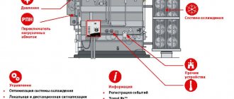
In conditions of limited space, other protection against neutral wire breakage is suitable. We are talking about modular devices installed in the floor electrical panel. They are compact and reliable in operation. Of course, they cannot equalize the voltage, but they can disconnect an apartment or house from the emergency network in the event of voltage surges as clearly as possible.
Among the models presented on the market, the buyer will find both inexpensive samples of devices that work only for automatic de-energization, as well as more advanced equipment that allows you to record the values of emergency values, as well as independently turn on the current after eliminating the danger.
With proper knowledge of electrical engineering, installation of protective devices can be done with your own hands. Otherwise, it is better to invite a specialist.
Causes of short circuit
A short circuit becomes possible when the current does not pass through “zero” to the ground loop A0, B0 and C0. Instead, the currents move along the external circuits AB, BC and CA, which are powered by a voltage of 360 volts. Thus, on one panel of the apartment there may be too little voltage, since the frugal tenant has turned off all electrical appliances, while on the other, a voltage close to linear is formed - 360 volts. This causes damage to the wires. The devices, in turn, overheat as a result of the supply of off-design currents to them.
To avoid such a situation and protect against a sudden surge in voltage, there are protection devices that are installed inside apartment panels. They are also placed in the housing of expensive electrical appliances to prevent breakdowns, for example, in refrigerators and freezers.
Wire Classification Options
The typical cable name contains letters and numbers. By decoding these symbols you can find out the main characteristics of products in this category:
- conductor (shell) materials;
- number of cores;
- cross-sectional area;
- Extra options.
Example of decoding (AVBbv-ng):
- A – the core is made of aluminum (copper is not marked);
- B – insulating shells are made of PVC;
- BB – protection against mechanical damage, made of steel tape without a damping gasket;
- ng – components that prevent combustion have been added to the polymer shell.
Ground wire color
By modern standards, the ground conductor is yellow-green. It usually looks like yellow insulation with one or two longitudinal bright green stripes. But there are also transverse yellow-green stripes in color. This color can be grounding.
In some cases, the cable may only have yellow or bright green conductors. In this case, the “earth” has exactly this color. It is displayed in the same colors on diagrams - most often bright green, but it can also be yellow. Signed on circuit diagrams or on ground equipment in Latin (English) letters PE. The contacts to which the “ground” wire must be connected are also marked.
Sometimes professionals call the grounding wire “neutral protective”, but do not be confused. This is an earthen one, and it is protective because it reduces the risk of electric shock.
What color is the neutral wire?
Zero or neutral is blue or light blue, sometimes blue with a white stripe. Other colors are not used in electrical engineering to indicate zero. It will be like this in any cable: three-core, five-core or with a large number of conductors.
What color is the neutral wire? Blue or light blue. “Zero” is usually drawn in blue on diagrams and signed with the Latin letter N. Experts call it a working zero, since, unlike grounding, it participates in the formation of the power supply circuit. When reading a diagram, it is often defined as "minus", while the phase is considered "plus".
Color of zero, neutral
The “zero” wire should be blue. In the distribution board it must be connected to the zero bus, which is designated by the Latin letter N. All blue wires must be connected to it. The bus is connected to the input via a meter or directly, without additional installation of the machine.
In the distribution box, all wires (except for the wire from the switch) of blue color (neutral) are connected and do not participate in switching. To the sockets, the blue “zero” wires are connected to the contact, which is designated by the letter N, which is marked on the back of the sockets.
Phase color
The designation of the phase wire is not so clear. It can be either brown, or black, or red, or other colors besides blue, green and yellow.
In an apartment switchboard, the phase wire coming from the load consumer is connected to the lower contact of the circuit breaker or to the RCD. In switches, the phase wire is switched; during switching off, the contact closes and voltage is supplied to consumers. In phase sockets, the black wire must be connected to the contact marked with the letter L.