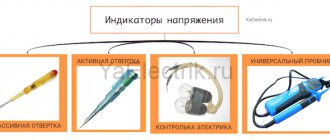
General information about indicators
Potential detection devices on current-carrying network elements operate on various principles related to the properties of electricity. Low voltage indicators are manufactured in accordance with the action of a certain quality indicator. There are standards that define the requirements for control devices.
Operating principle
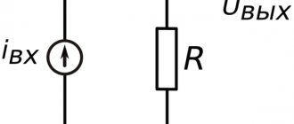
Inside every object there are electrical charges: cations, anions, electrons. Their number determines the magnitude of the positive or negative potential. The difference in the values of this indicator is the voltage, the formation of which in a closed circuit causes the movement of charges - electric current. This property is used when creating devices for detecting potential:
- a resistance is installed in the path of the particles, reducing their concentration to a minimum safe for humans;
- the remainder of the electricity is converted into magnetic, light, sound energy;
- Based on the intensity of the received signal, one judges the presence or absence of potential on the conductor.
A contact or two terminals of the device are connected to the network elements and the presence or absence of current is verified. The available voltage will be indicated by the sound of the built-in microspeaker, an LED light or the arrow of a measuring device.
Product classification
Knowledge of the range of industrially produced devices will help you select the most suitable low voltage indicator for your conditions. The division of modifications occurs according to different criteria. Manufacturers offer designs in the following categories:
- Depending on the type of current being measured - for operation in DC or AC voltage circuits.
- According to the number of operational contacts - single- and double-pole. The latter are universal; they are used to determine the potential in any circuit. The principle of their operation is based on the passage of active electrons. The first type of indicators has a different device - single-pole ones: they use the properties of capacitive current, and use devices only in alternating networks.
- In connection with live parts - contact and non-contact, allowing you to detect voltage indirectly without touching the network element. An example of the latter type of devices are Chinese-made indicators: MS-8 and 58. They consist of an LED, radio components and are powered by miniature batteries, the non-contact measurement range is 70–600 V, polarity detection is 1.5–36 V. For inexperienced craftsmen, such an indicator It’s better not to use it: it reacts to all surrounding objects.
- Depending on the type of indicator - digital and LED.
There are differences in devices in terms of measurement range and appearance. The voltage allowed for operation is marked on the device body. Using a 220 Volt indicator on a 0.4 kV network is dangerous to life.
Manufacturing requirements
Voltage indicators up to 1000 V are subject to certain conditions that are mandatory for device manufacturers. The full list of requirements is set out in the state standard. The most important conditions are the following:
- light and sound signals are clearly recognized, the interval between pulses lasts no more than a second, the load on the indicator is up to 50 V;
- the single-pole pointer is enclosed in 1 housing, on which there is an electrode tip, and on the handle there is a contact for the operator’s finger;
- Bipolar devices have 2 separate shells connected by a meter-long wire and each equipped with a working electrode with an open tip of up to 7 mm.
This will be interesting to you Digital device multimeter and measurement with a multitester
Voltage indicators can combine other functions - searching for a phase conductor, checking the integrity of the network, establishing polarity. The condition for expanding the capabilities of the device is maintaining the safety of use for its main purpose. Before starting work, the indicator is checked with a potential of 2 kV, turned on for a minute.
In some cases, preference is given to bipolar voltage indicators, and the safest is considered to be non-contact - it reads information through a magnetic field. When checking for potential, the connection between the pointer and the current-carrying element is maintained for at least 5 seconds.
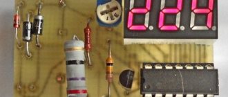
What it is
An electrical tester is a device that is used to measure and determine the voltage in an electrical circuit. The main difference from a multimeter is the simplicity of the design and use of this unit; it operates quickly and can be used in any conditions.
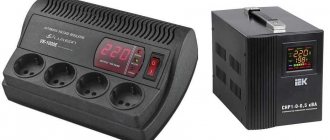
Photo - resistance tester
There are also more compact probe testers that can be used to measure the voltage level in an outlet or any other electrical device, for example, generators in a car. They differ from standard indicators in their small size, and they also have simpler operating instructions.
Previously, a pointer tester, such as ASKOM, was mainly used. It has a reliable operating circuit, is powered by batteries and provides fairly reliable and accurate operation.
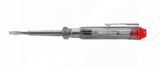
Description of single-pole devices
An indicator screwdriver is a simple and popular tool among home craftsmen. It also resembles a school pen made of transparent dielectric, equipped with additional resistance and a neon light bulb. The detectable voltage is 100–500 V with an alternating current frequency in the network of 50 Hz. The scope of application of the device is checking secondary circuits, cartridge phases, sockets and switches. The tip of the pointer is pressed against the conductor being tested, and the other contact of the indicator is closed by touching the finger, organizing an electrical circuit:
- phase potential;
- element being checked;
- internal circuit of the device to the terminal pad;
- hand and other parts of the human body;
- Earth.
The strength of the flowing current is safe and does not exceed 0.3 mA, but it is enough to glow neon. Indicators of this type have many names: IN-91, INO-70, UNN-90, UNN-1M. The range of potentials determined by the UN-453M device is from 24 to 1200 V.
DC Voltage Check
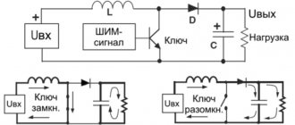
The indicator circuit we considered can be used not only in AC circuits, but also in DC circuits. If we touch the “plus” with a probe attached to the anode of the LED, and with another probe we touch the “minus” of the electrical installation, the indicator will light up. If the indicator is connected in the opposite direction, the LED will not light up. Thus, we will not only be able to check the presence of voltage, but also determine the polarity of the source.
The simplest LED voltage indicator circuit can be improved. To do this, you need to make one change to it: replace the silicon diode with an LED. After this replacement, both LEDs of the indicator connected to alternating voltage will light up simultaneously. When checking for constant voltage, one of the LEDs will light up. Which LED will light depends on the polarity of the indicator connection.
If the indicator can glow in different colors, then by default green LEDs indicate normal operation, such as correct polarity.
Double pole indicators
The principle of operation of indicators of this type is based on comparing the potentials in 2 current-carrying parts of the equipment being tested: zero and phase. Unlike single-pole indicators, these devices are equipped with two probes. A person does not come into contact with the controlled voltage and is separated from its influence by a layer of insulation. The indicator includes a signal lamp and 2 resistors: a shunt and a current-limiting one. The connection between the probes is made with a rubberized flexible wire.
You might be interested in Oscilloscope: operating principle, design and application
Of the old models of bipolar voltage indicators up to 1000 V, MIN 1 and UNN-10 with an operating potential range of 70–660 volts are still used. The signal lamp of these devices lights up at 60–65 V. Using the indicated products, the circuit is checked for integrity. Simple versions include indicators of the PIN-90, UN-500, UNNU-1 series - they only detect the presence of voltage. More advanced models ELIN-1, IPM also indicate the potential value and polarity.
LEDs of all colors, neon bulbs and digital indicators are used as a signal. There are also combined indicators - sound is added to the glow, which increases the safety of handling the device. The most famous digital two-pole voltage indicator is the multimeter. It is able to determine the magnitude of AC and DC potential, strength and frequency. The device is often used to solve everyday problems.
Simple homemade products for a car, tips for car enthusiasts and do-it-yourself diagrams
This mode allows you to measure the voltage in wires plastered in the wall, as well as identify their route.
3 thoughts on “Battery indicator on LEDs circuit for beginners”
When the input voltage is 0, this indicator is considered one of the essential tools of an electrician.
Having gouged the wall, I pulled out the old wire and was about to install a new one, but I decided to check it again. Let's connect one probe to one socket of the socket, and the second to the second. Or assemble a simple “blinker” yourself using two bipolar transistors. Which is better to choose? All devices have their pros and cons, which must be taken into account when purchasing them. When a screwdriver is connected unipolarly to a current-carrying phase conductor and a finger touches the touch pad, the neon lamp will light up, signaling the presence of mains voltage. The LED is connected in series with the battery through a field-effect transistor channel.
Logical level indicator probe on four transistors To indicate fine tuning, radio receivers often use simple devices containing one, and sometimes several, LEDs of different colors. For such purposes, it is better to use a multimeter in dialing mode. This turns out to be sufficient for the human eye to normally perceive light from the LED as continuous radiation. Methods for controlling the state of an LED using transistor switches Fig. sxematube - circuit of a simple voltage indicator more or less, simple circuit of a voltage indicator
Use of control devices
Before each use, the indicator is inspected for damage to the housing or insulation, after which the functionality of the indicator is checked by touching a phase that is known to be energized. A defective device will cause an error resulting in a short circuit or personal injury. When taking measurements, you must be careful and follow the basic rules:
- the indicator must correspond to the network parameters - it would be useful to verify this by looking at the markings on the device body;
- during the check, take a stable position, excluding unexpected falls and contact with grounded conductors;
- One way to avoid unwanted contact is to keep your free hand in your pocket so you don't accidentally create a closed circuit for electrical charge.
When working with a single-pole indicator, it is prohibited to use dielectric gloves: contact of the plate on the indicator handle with the operator’s finger must be ensured. We must remember that electricity is dangerous - not only beginners, but also experienced installers die from mistakes.
You might be interested in Features of assigning group 4 for electrical safety