Dismantling and installation of wires.
3.1. Work on the dismantling and installation of the wire must be carried out according to the technological map or PPR in the presence of the work manager with group V along the work order. 3.2. Before starting the robot, the foreman must personally inspect the lines and outline measures to ensure safe work. 3.3. It is permissible to proceed with decoupling of wires only after strengthening the defective support using one of the above methods. 3.4. When replacing wires, start decoupling from top to bottom. Having released the ties of the upper wire, lower it to the ground carefully (without jerking) using a rope. The newly suspended wire is lifted onto supports, sighted and tied to the insulators. In this sequence of operations, the remaining wires are dismantled and installed. It is forbidden to untie the last wire until the newly suspended wires are secured. Before removing the wires from the corner support, it is necessary to secure it with a guy rope. If there is a large degree of decay of the supports, it is necessary to use fastening devices or carry out work using a tower, and it is strictly forbidden to attach the dismantled wires, at least temporarily, to the basket or telescope of the tower. 3.5. Do not climb or stand on an intermediate support if less than two wires are attached to it. 3.6. It is prohibited to climb and work on corner supports with pin insulators from the inside corner.
How much is the distance between lighting poles, lamp posts?
Distance between lamp posts, lighting supports
When installing lamp posts, lighting supports in the city, along the road, the distance between the outdoor lighting supports of the city is determined based on the number of lighting lamps installed on the support, their power and the height of the lamp installation above the road. The distance between reinforced concrete lighting poles when installing lamp poles along roads is determined using the same table. The calculation of the distance between lighting supports is based on road illumination standards. This calculation allows you to answer the questions: “How many meters are between the lamp posts?”, “What is the distance between the lamp posts?”, “What is the span between the lamp posts?”. The ratio of the pitch of lamps to the height of their suspension on streets and roads of all categories should be no more than 5:1 with one-sided, axial and rectangular placement of lamps and no more than 7:1 with a checkerboard placement pattern. The table shows the maximum distances between lighting supports, taking into account the required illumination of the roadway.
How many meters between the support and the road when installing lighting poles?
Electrical installation of outdoor lighting fixtures is carried out on street lighting poles, lighting masts, power line poles and other structures. To illuminate this or that part of the street, it is necessary to install an external lighting system in accordance with the standards for installing electrical poles.
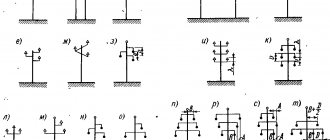
Dismantling supports.
4.1. Work on dismantling supports, as well as replacing support elements, must be carried out according to the technological map or PPR in the presence of the work manager with group V along the way. 4.2. On the eve of the work on dismantling the supports, the foreman must personally inspect the section of the line and outline measures to ensure the safe execution of the work. 4.3. Rejection of supports must be carried out in accordance with the requirements of the instructions “On the rejection of wooden elements of supports” and “On the rejection of reinforced concrete supports and reinforced concrete attachments”. 4.4. The methods for felling the support are determined on site by the worker who issued the work order or the work manager. In addition, before going to work on a 0.4 - 6-10 kV overhead line on reinforced concrete supports, the work manager must check the documentation for the presence of single-phase ground faults on the overhead line. 4.5. Before assigning team members to work stations, the foreman briefs the team. 4.6. When dismantling supports using a truck crane, the sling is secured from a telescopic tower or aerial ladder above the center of gravity of the support, and the slack is removed until tension is reached. The support is released from the bandages and by turning the crane boom it is retracted in the desired direction and lies on the ground or is loaded. 4.7. The truck crane must be installed in such a way that the angle between the axis of rotation and the boom is minimal, the outriggers are set and secured, and people are removed from the work area of the truck crane. 4.8. When felling a support, traction cables and guy ropes must be attached to the upper part of the support before work begins to free the base of the support. 4.10. The tension of the cable when felling the support should be carried out evenly with due care to avoid breaking the cable.
Distance between transmission line towers: 10 kV, 110 kV and 35 kV transmission line poles
The electricity everyone needs is transmitted through wires suspended from poles of various designs and power lines. For safety, the distance between power line supports and their height are of great importance. GOST regulates all sizes based on the current strength in the wires, material and design of the support. The location of power transmission line supports in open areas or in populated areas is also of great importance.
Factors on which the distance between pillars depends
In different places, the distance between power line poles and the height of the wire differ. The values are calculated based on the fact that the tension of the wire and its sagging will create prevailing horizontal loads between the supports.
The second important element is the strength of the icing in a particular area and the resistance to wind swing. The value is calculated for each region separately depending on climatic conditions. In addition, what distance should be between the pillars and supports depends on the following factors:
- network voltage,
- the type of settlement through which the line passes,
- distance from populated areas,
- number of overhead lines,
- wire type.
Adjustment of distances between power transmission line poles is carried out primarily in populated areas. Based on general requirements, supports should not block free access to the yard, block the path for pedestrians, or stand directly in front of the front facades of buildings and entrances to houses.
A fence is installed on the side of the road to prevent cars from hitting the supports. These are concrete pillars, bollards and high barrier curbs.
Each high-voltage pole must be marked. At a height of 2.5–3 m, the following data is applied:
- Serial number.
- Network voltage value.
- Year of installation of the structure.
- Width of the security zone.
- Distance from ground to communication cables.
- Phone number of the owner - the organization operating this network.
Metal structures are protected from corrosion and are regularly coated with a protective primer or ship paint.
The numbering of supports is carried out from the current source.
The maximum deflection of wires is calculated taking into account icing, which is divided into 6 categories, and wind force. Tensioners are installed at the suspension points, ensuring a minimum angle of deviation of the horizontal position of the cable and the least sagging.
Bare wire is used for lines outside cities and towns. It will be installed at the maximum possible height directly on the insulators using special bolted tires.
Mains voltage
The distance between the supports is determined depending on the voltage in the wires they carry:
- 0.4–1 kV – distance within 30–75 m,
- 10 kV – spans up to 200 m,
- 220 kV – distance between supports up to 400 m,
- over 330 kV - supports can be located from each other at a maximum distance of 700 m.
The wires are suspended in parallel on insulators at a height that also depends on the voltage. If it is up to 1000 V, then the line is fixed at a height of 7 m.
The permissible sag and the distance to the bottom point are also determined depending on the voltage. In cities, towns of individual housing construction and SNT, the lowest sagging point should be higher than 6 m from the ground.
Span between supports in residential communities and beyond
A settlement of any type, a holiday village, a city and a village have the same status for the passage of power lines through them. The distance between the pillars is determined to be up to 70 m, provided that at the moment of maximum icing they do not sag below 6 m in places where the road and sidewalk pass. The wire must be insulated.
Street lighting in the private sector is installed on poles located along the road at a distance of 30–50 m from each other. Electricity is supplied to the garage and house through a self-supporting insulated wire. The entry point must be at least 4 m from the ground surface.
If a cable is pulled from a pole through a site, an intermediate support is installed, providing a suspension at a height of 7 m and a maximum sag of up to 6 m. Trees are planted at a distance of more than 5 m from the wire. Directly below the line you can make a vegetable garden with plants 0.5 m tall. The shrub is planted at a distance of at least a meter from the cable projection line.
High-voltage power lines over 300 kV should not pass through populated areas of any type. The distance from the nearest residential building must be 100 m. The distance to the border of the site without buildings is the minimum width of the sanitary zone in one direction.
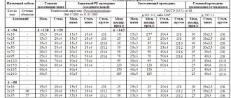
The basis for calculating the length of transmission line spans is TP 25.0038, which reflects the development of design distances for 0.28–35 kV overhead line supports. A typical project contains tables of span sizes between reinforced concrete and metal supports depending on the degree of icing, wind load and type of wire cross-section and insulation.
Based on the data contained in it, you can design at what distance to install a pole with SIP. If an electric wire, metal or copper, is stretched without insulation, then this will determine how much the span between the pillars will change.
5.REPLACEMENT OF WIRES IN THE SPANS INTERSECTION WITH OTHER OPERATING LINES.
5.1. All work on overhead lines above 1000 V at the intersection with the existing overhead line is carried out side by side under the supervision of the work manager with group V from the managers and specialists servicing this electric power line. installation. 5.2. When performing work on overhead line wires in the span of intersection with another live line, grounding must be installed on the support where the work is being done. When performing work on hanging, replacing or adjusting the wire, it should be grounded on both sides of the intersection. In this case, when replacing wires, it is necessary to ground both the wire being removed and the wire being suspended on both sides of the intersection. 5.3. In the crossing spans of overhead lines, when replacing wires and related insulators and fittings located below live wires, on both sides of the intersection through grounded wires, it is necessary to throw ropes made of plant or synthetic fibers, securing them to anchors, structures, etc. . The wire should be lifted smoothly, without jerking, to avoid tripping the live wires located above. 5.4. In crossing spans on overhead lines, work on supports, insulators and fittings located above live wires must be carried out according to the PPR, which must include measures to prevent the wires from lowering. It is prohibited to replace or adjust the wire when performing such work without removing the voltage from the underlying wires.
Country roads
The answers to these questions are contained in the PUE (“Electrical Installation Rules”). For overhead lines with voltage up to 1 kV there is the following point:
2.4.90. When crossing and paralleling overhead lines with railways and roads, the requirements set out in Chapter 2.5 must be met.
And Chapter 2.5 sets out the requirements for overhead lines with voltages above 1 kV. We will be guided by them.
Table 2.5.35. The shortest distances when crossing and approaching overhead lines with highways.
2.5.262. To prevent vehicle collisions with overhead line supports located at a distance of less than 4 m from the edge of the roadway, road barriers of group I must be used