Generator voltage regulator
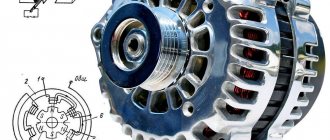
The generator converts electricity.
Without a generator, the entire on-board system of the car would not work. A special sensor is connected to the magnet winding. Simple springs are the driving device. A small lever is used for the comparison device. The group of contacts plays the role of an actuator. A constant resistance is an adjustment element that is often used in machines. During operation of the generator, a current arises at its output. The resulting current passes into the winding of the magnetic relay. As a result, a magnetic field appears and, under its influence, the lever arm moves apart. A spring begins to act on it and plays the role of a comparing device. When the current exceeds the required values, the contacts on the magnetic relay move apart. At this time, the constant resistance in the circuit is turned off. Less current flows into the winding.
Perhaps it is useful for everyone to know what the accuracy class of an electric meter is.
Current measurement
Now let's take a slightly different measurement. Let's measure the current or amperage in a circuit using a multimeter by setting it to "mA" (milliamps). To measure current, remember that: • you can only measure current as it passes through your device; • your measuring device must be built into the circuit; • Too much current may burn the fuse inside your appliance. You should make sure that the multimeter is set to a mode specifically for measuring current in milliamps ( Fig. 8 ), and not voltage, as was previously the case.
Fig.8.
Connect your tester to the circuit as shown in Fig. 9, a, b . Do not turn the potentiometer more than halfway. The potentiometer's resistance will protect your tester, just like the LED. If too much current is being passed through the tester, you may find yourself replacing the tester's internal fuse.
Fig.9.
If you change the position of the potentiometer slightly, turning it one way or the other, you will find that changing the resistance in the circuit will lead to a change in current. This may explain why the LED burned out in the previous experiment. Too much current makes it hot, and that heat will melt it from the inside, like the fuse in Experiment 2 above.
Higher resistance limits the current or its ampere value.
Now build a multimeter into another part of the circuit under test, as shown in Fig. 9, b . As you turn the potentiometer forward or backward, you will get exactly the same results as in the circuit shown in Fig. 9 . This happens because the current at all points in such a circuit has the same value. This is all true because the flow of electrons has no other path. Now it's time to look at some numbers. There's one last thing to check here. Disconnect the LED and replace it with a 1 kOhm resistor, as shown in Fig. 10 . The total resistance in the circuit will now be 1 kOhm plus the resistance of the potentiometer, depending on the position of the control axis in which you installed it. (Of course, the multimeter also has some resistance, but it is so small that we can ignore it).
Fig. 10.
First, turn the potentiometer axis all the way counterclockwise, and you will get a total resistance in the circuit equal to 3 kOhms. Your multimeter should show approximately 2 mA. Then turn the potentiometer axis to the middle position and you will get a total resistance in the circuit of about 2 kOhms. The current in this case should be about 3 mA. Now turn the potentiometer axis clockwise all the way. The total resistance in the circuit will become 1 kOhm, and you will get a current that will be about 6 mA. You may notice that if you multiply the resistance by the current, each time you get the number 6 - which just means the amount of voltage that is applied to the circuit ( Table 1 ).
Table 1.
| Total resistance, kOhm | Current strength, mA | Voltage, V |
| 3 | 2 | 6 |
| 2 | 3 | 6 |
| 1 | 6 | 6 |
In fact, we can say: volts = kiloohms x milliamps. But wait a second: 1 kOhm is 1000 Ohms, and 1 mA is 1/1000 A. So our formula should really look like this: volts = (ohms x 1000) x (amps x 1/1000). After reducing the numerator and denominator by 1000, we get: volts = ohms x amps. This is known as Ohm's law.
| Fundamentals |
| Series and parallel Before continuing, you must know how the resistance in a circuit changes when resistors are connected in series and in parallel ( Fig. 11-13 ). It should be remembered that:
When you connect two resistors of the same value in series, you double the total resistance because the electric current is traveling through two obstacles in series. Rice. 11. All voltage is applied to one resistor in accordance with Ohm’s Law and a current of U/R = 6 V/1000 Ohm = 0.006 A = 6 mA flows through it.
Rice. 13. when two identical resistors are connected in parallel, then the full voltage is applied to each of them, i.e. the voltage across them is 6 V. Electric current passes through them simultaneously, so the total resistance becomes half what it was. In accordance with Ohm's Law, a current passes through the circuit equal to U/R = 6 V/500 Ohm = 0.012 A = 12 mA. When two resistors of the same value are connected in parallel, then you make the total resistance into two paths that it can take, instead of one. In practice we don't need to install resistors in parallel, but we often need to connect other types of components this way. For example, the light bulbs in your house are connected this way. Therefore, it is very useful to understand that the resistance of a circuit decreases if you add components to it in parallel. |
Adjustment features
It makes sense to talk about this or that 12 volt regulator only if you provide additional data:
- DC or AC voltage must be regulated;
- what is the maximum current in the load;
- the magnitude of the potential difference in front of the regulator;
- load voltage parameters in the regulation range.
Each of the listed parameters is associated with certain technical solutions that are reflected in the diagram. The general circuit of the regulator is a load that is connected to some device. It is conventionally indicated by a rectangle in the diagram shown below. Inside this rectangle there may be one or another diagram that corresponds to the additional data mentioned above. The simplest regulator is a variable resistor. It allows you to regulate AC voltage without distortion. This resistor is also applicable for direct current.
Circuit with variable resistor.
Elementary circuit of a regulator Circuit with a variable resistor
If the potential difference at the input is significantly greater than 12 volts at the output, energy will be lost in the regulator. The variable resistor will generate heat. To avoid heat loss, it is necessary to use variable inductance on alternating current, which can be LATR. Its throughput is limited, as in a variable resistor, by the design of the moving contact. But if switching is permissible by placing jumpers with reliable contacts between the turns, a significant current can be obtained.
Inductive regulator
Another way to regulate 12 volt alternating voltage with your own hands is to change the inductance of the regulator. To do this, manually change either the gap or the number of turns specifically designed for this. An adjustable welding transformer used to power a voltaic arc is designed according to this principle. If the 12 volt voltage regulator does not have the properties of a stabilizer and is controlled by yourself, the potential difference across the load must be monitored with a voltmeter.
A variable resistor and variable inductance can also be used as a current regulator. In this case, it is necessary to monitor the current in the load with an ammeter. If the voltage parameters at the load are not specified, with the exception of its value of 12 V, you can regulate it with a dimmer. This can be a powerful regulator since it is usually thyristor based. And modern thyristors are produced for a very wide range of potential difference and current.
Adjustable stabilizer from 0 to 12 volts 3 amps
By excluding the current protection unit from the circuit in Figure 1 and replacing transistors VT1 VT2 with more powerful ones, you can build an adjustable stabilizer from 0 to 12 volts with a load current of up to 3 amperes. The diagram of such a stabilizer is shown in Figure 2.
When repeating the circuit of the adjustable stabilizer in Figure 2, it is necessary to pay attention to the thermal parameters of the rectifier bridge VD1...VD4 and transistor VT2. The VT2 transistor must be installed on a radiator with a cooling area of at least 250 sq.cm, and the diodes must be rated for a current of at least 10 amperes (D245...D247).
The circuit of the adjustable stabilizer does not show the supply transformer, which should provide the required current
on the secondary winding.
Regulation with stabilization
To obtain the specified voltage or load current parameters, stabilizers are used. In them, the output voltage or current is compared with a reference value, and at a minimum specified change, the regulator is automatically compensated by the control of the corresponding semiconductor device. There are a huge number of different schemes for various stabilizers. The easiest to use are integrated circuits.
- Linear voltage stabilizer with adjustment on TL431 and NPN transistors
Appearance and connection diagram of the 12 V stabilizer microcircuit
Such ready-made stabilizers are very convenient for powering LEDs both in cars and in lighting systems. When powered from a 220 volt network, a step-down transformer with a rectifier is required, connected to the input. Since in many cases the load parameters are very specific, special voltage and current stabilizers are made. They can operate in both continuous and pulse modes. But that's a completely different story...
5 common questions asked by beginning radio mechanics; 5 best transistors for regulators, circuit composition test
An electrical voltage regulator is needed so that the voltage can be stabilized. It ensures reliable operation and longevity of the device.
The regulator consists of several mechanisms.
TEST:
The answers to these questions will allow you to find out the composition of the 12 volt voltage regulator circuit and its assembly.
- What resistance should the variable resistor have?
a) 10 kOhm
What happened
The updated installation process itself took no more time than the previous one. In this case, what was obtained was not a simple voltage regulator that is connected to a stabilized voltage power supply; the assembled circuit, when connected even to a network step-down transformer with a rectifier at the output, itself provides the necessary stabilized voltage. Naturally, the output voltage of the transformer must correspond to the permissible parameters of the input voltage of the KR142EN12A microcircuit. Instead, you can use the imported analogue integrated stabilizer LM317T. Author Babay iz Barnaula .
Discuss the article TWO SIMPLE VOLTAGE REGULATORS
We present a powerful stabilized 12 V power supply. It is built on an LM7812 stabilizer chip and TIP2955 transistors, which provides a current of up to 30 A. Each transistor can provide a current of up to 5 A, respectively, 6 transistors will provide a current of up to 30 A. You can change the number of transistors and get desired current value. The microcircuit produces a current of about 800 mA.
A 1 A fuse is installed at its output to protect against large transient currents. It is necessary to ensure good heat dissipation from transistors and the microcircuit. When the current through the load is large, the power dissipated by each transistor also increases, so that excess heat can cause the transistor to fail.
In this case, a very large radiator or fan will be required for cooling. 100 ohm resistors are used for stability and to prevent saturation as... the gain factors have some scatter for the same type of transistors. The bridge diodes are designed for at least 100 A.
Notes
The most expensive element of the entire design is perhaps the input transformer. Instead, it is possible to use two series-connected car batteries. The voltage at the input of the stabilizer must be a few volts higher than the required output (12V) so that it can maintain a stable output. If a transformer is used, the diodes must be able to withstand a fairly large peak forward current, typically 100A or more.
Read also: Wrench with adjustable torque
No more than 1 A will pass through LM 7812, the rest is provided by transistors. Since the circuit is designed for a load of up to 30 A, six transistors are connected in parallel. The power dissipated by each of them is 1/6 of the total load, but it is still necessary to ensure sufficient heat dissipation. Maximum load current will result in maximum dissipation and will require a large heatsink.
To effectively remove heat from the radiator, it may be a good idea to use a fan or water-cooled radiator. If the power supply is loaded to its maximum load, and the power transistors fail, then all the current will pass through the chip, which will lead to a catastrophic result. To prevent breakdown of the microcircuit, there is a 1 A fuse at its output. The 400 MOhm load is for testing only and is not included in the final circuit.
Computations
This diagram is an excellent demonstration of Kirchhoff's laws. The sum of currents entering a node must be equal to the sum of currents leaving this node, and the sum of the voltage drops on all branches of any closed circuit circuit must be equal to zero. In our circuit, the input voltage is 24 volts, of which 4V drops across R7 and 20 V at the input of LM 7812, i.e. 24 -4 -20 = 0. At the output, the total load current is 30A, the regulator supplies 0.866A and 4.855A each 6 transistors: 30 = 6 * 4.855 + 0.866.
The base current is about 138 mA per transistor, to get a collector current of about 4.86A, the DC gain for each transistor must be at least 35.
TIP2955 meets these requirements. The voltage drop across R7 = 100 Ohm at maximum load will be 4V. The power dissipated on it is calculated by the formula P= (4 * 4) / 100, i.e. 0.16 W. It is desirable that this resistor be 0.5 W.
The input current of the microcircuit comes through a resistor in the emitter circuit and the B-E junction of the transistors. Let's apply Kirchhoff's laws once again. The regulator input current consists of 871 mA current flowing through the base circuit and 40.3 mA through R = 100 Ohms. 871.18 = 40.3 + 830. 88. The input current of the stabilizer must always be greater than the output current. We can see that it only consumes about 5 mA and should barely get warm.
Testing and Bugs
During the first test, there is no need to connect the load. First, we measure the output voltage with a voltmeter; it should be 12 volts, or a value not very different. Then we connect a resistance of about 100 Ohms, 3 W as a load. The voltmeter readings should not change. If you do not see 12 V, then, after turning off the power, you should check the correctness of installation and the quality of soldering.
Read also: How to melt tin at home
One of the readers received 35 V at the output, instead of the stabilized 12 V. This was caused by a short circuit in the power transistor. If there is a short circuit in any of the transistors, you will have to unsolder all 6 to check the collector-emitter transitions with a multimeter.
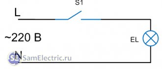
An adjustable voltage stabilizer from 0 to 12 volts and a load current of up to 1 ampere is presented in Figure 1.
An alternating voltage of 12 volts is rectified by the diode bridge VD1...VD4, smoothed by filter C1 C2, and supplied to a parametric stabilizer on the zener diode VD1. The 12 volt voltage generated by the zener diode is applied to resistor R2. From the motor of the variable resistor R2, the voltage is supplied to the analog switch VT1 VT2, connected according to the circuit of a composite transistor. The degree of opening of the key depends on the position of the variable resistor R2 slider, i.e. in the lower position of the regulator according to the diagram, the voltage at the base is zero and transistors VT1 VT2 are closed, no voltage is supplied to the load. In the upper position of the regulator R2 according to the diagram, the voltage at the base is maximum. The transistors are fully open, and the voltage from the rectifier is applied to the load, with the exception of the drop at the collector-emitter junction of transistor VT1.
The adjustable stabilizer circuit in Figure 1 contains a current protection circuit on transistor VT3. If the current on resistor R4 exceeds 1.2 amperes, due to the voltage drop across it, transistor VT3 opens, thereby shunting resistor R2 with the collector-emitter transition, the voltage on R2 decreases, causing transistors VT1 VT2 to close.
The current protection threshold is selected by resistance R4, and with its resistance of 0.5 ohms it is approximately equal to 1.1...1.25 amperes.
How to connect 5 parts of a 12 volt regulator.
Variable resistor 10 kOhm.
This is a 10kohm variable resistor. Changes the current or voltage in an electrical circuit, increases resistance. This is what regulates the voltage.
Radiator. Needed to cool devices in case they overheat.
Resistor for 1 com. Reduces the load on the main resistor.
Mains voltage regulator
Let's look at how to make a 220V voltage regulator with your own hands. There is a simple circuit that does not require expensive radio components. You will need the following set of elements:
- 2 resistors of 1 kOhm;
- Variable resistance 1mOhm;
- A pair of capacitors 47 nF, and 0.01 μF;
- Dinistor. Its installation is carried out by either side (it has no polarity);
- Triac and radiator for it;
- Screw terminal blocks.
If you want to get a smooth voltage regulation, then it is better to install it on a variable resistance of 500 kOhm, but the adjustment range will not fall below 120V.
A 1mOhm variable resistor will regulate more tightly, but the range will be up to 60V. Having made the printed circuit board, we mount screw terminal blocks on it. Then we solder all the elements, and the last thing to install is a triac with a radiator.
This completes the installation, you just need to wash the resulting board with an alcohol solution, and you can check it.
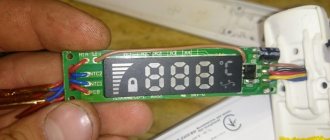
How to make a diagnosis without removal?
It is not recommended to carry out such a check, since there is no way to assess the condition of the brush assembly. But cases are different, so even such a diagnosis can bear fruit. To work, you will need a multimeter or, if you don’t have one, an incandescent lamp. The main thing for you is to measure the voltage in the vehicle’s on-board network and determine if there are any surges. But they can also be noticed when driving. For example, the light flashes when the engine crankshaft speed changes.
But measurements taken using a multimeter or voltmeter with a stretched scale will be more accurate. Start the engine and turn on the low beams. Connect a multimeter to the battery terminals. The voltage should not exceed 14.8 Volts. But it is also impossible for it to fall below 12. If it is not in the permitted range, then the voltage regulator is broken. It is possible that the contacts at the connection points between the device and the generator are broken, or the wire contacts are oxidized.
Scheme number 1
There was a stabilized switching power supply that gave an output voltage of 17 volts and a current of 500 milliamps. A periodic change in voltage was required in the range of 11 - 13 volts. And the well-known voltage regulator circuit on one transistor coped with this perfectly. I added only an indication LED and a limiting resistor to it. By the way, the LED here is not only a “firefly” signaling the presence of output voltage. With the correct value of the limiting resistor, even a small change in the output voltage is reflected in the brightness of the LED, which provides additional information about its increase or decrease. The output voltage could be changed from 1.3 to 16 volts.
KT829, a powerful low-frequency silicon compound transistor, was installed on a powerful metal radiator and it seemed that, if necessary, it could easily withstand a heavy load, but a short circuit occurred in the consumer circuit and it burned out. The transistor has a high gain and is used in low-frequency amplifiers - you can really see its place there and not in voltage regulators.
On the left are removed electronic components, on the right are prepared for replacement. The difference in quantity is two items, but in terms of the quality of the circuits, the former and the one that was decided to be collected, it is incomparable. This begs the question: “Is it worth assembling a scheme with limited capabilities when there is a more advanced option “for the same money”, in the literal and figurative sense of this saying?”
Simple power regulator circuit
You can adjust the power of the soldering iron using analog or digital soldering stations for this purpose. The latter are quite expensive, and it is not easy to assemble them without experience. While analog devices (which are essentially power regulators) are not difficult to make with your own hands.
Here is a simple diagram of a device using thyristors, thanks to which you can regulate the power of the soldering iron.
The simplest regulator
Radioelements indicated in the diagram:
- VD – KD209 (or similar in characteristics)
- VS-KU203V or its equivalent;
- R1 – resistance with a nominal value of 15 kOhm;
- R2 – variable resistor 30 kOhm;
- C – electrolytic type capacitance with a nominal value of 4.7 μF and a voltage of 50 V or more;
- Rn – load (in our case it is a soldering iron).
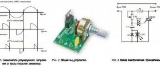
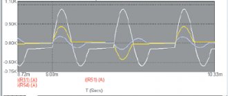
This device regulates only the positive half-cycle, so the minimum power of the soldering iron will be half the rated one. The thyristor is controlled through a circuit that includes two resistances and a capacitance. The charging time of the capacitor (it is regulated by resistance R2) affects the duration of the “opening” of the thyristor. Below is the operating schedule of the device.
The influence of resistance R2 on the operation of the regulator
Explanation of the picture:
- graph A – shows a sinusoid of alternating voltage supplied to the load Rn (soldering iron) with a resistance R2 close to 0 kOhm;
- graph B – displays the amplitude of the sinusoid of the voltage supplied to the soldering iron with a resistance R2 equal to 15 kOhm;
- graph C, as can be seen from it, at the maximum resistance R2 (30 kOhm), the operating time of the thyristor (t2) becomes minimal, that is, the soldering iron operates with approximately 50% of the nominal power.
The circuit diagram of the device is quite simple, so even those who are not very well versed in circuit design can assemble it themselves. It is necessary to warn that when this device operates, a voltage dangerous to human life is present in its circuit, therefore all its elements must be reliably insulated.
As already described above, devices operating on the principle of phase regulation are a source of strong interference in the electrical network. There are two options for getting out of this situation:
- supply voltage through a smoothing filter (its circuit is easy to find), the simplest implementation option is a ferrite ring with a network cable wrapped around it;
Filter based on a ferrite ring from the monitor cable - To assemble a device that does not create interference, we will give an example of such a circuit.
Types of 12V stabilizers
Depending on the design and method of maintaining a 12-volt voltage, there are two types of stabilizers:
- Pulse stabilizers, consisting of an integrator (battery, high-capacity electrolytic capacitor) and a switch (transistor). Maintaining the voltage in a given range of values occurs due to the cyclic process of accumulation and rapid release of charge by the integrator when the key is open. According to their design features and control method, such stabilizers are divided into key devices with a Schmitt trigger, equalizers with pulse width and pulse frequency modulation.
- Linear - voltage-stabilizing devices in which zener diodes or special microcircuits connected in series are used as a regulating device.
The most common and popular among car enthusiasts are linear devices, characterized by ease of self-assembly, reliability and durability. The pulse type is used much less frequently due to the high cost of parts and the difficulties of independent production and repair.
Dinistor and 4 types of conductivity.
This device is called a trigger diode. Has little power. There are no electrodes in its interior.
The dinistor opens when the voltage increases. The speed at which voltage increases is determined by the capacitor and resistors. All adjustments are made through it. Works on direct and alternating current. You don’t have to buy it, it is in energy-saving lamps and is easy to get from there.
It is not often used in circuits, but in order not to spend money on diodes, a dinistor is used.
It contains 4 types: PNP N. This is the electrical conductivity itself. An electron-hole transition is formed between 2 adjacent regions. There are 3 such transitions in the dinistr.
Scheme:
We connect the capacitor. It starts charging with 1 resistor, the voltage is almost equal to that in the network. When the voltage in the capacitor reaches the level of the dinistor, it will turn on. The device starts working. Don't forget about the radiator, otherwise everything will overheat.
12 volt speed controller for motor with brake.
Compound:
- Relay - 12 volts
- Theristor KU201
- Transformer for powering the motor and relay
- Transistor KT 815
- Wiper valve 2101
- Capacitor
It is used to regulate the wire feed, so it has a motor brake implemented using a relay.
We connect 2 wires from the power supply to the relay. The relay is supplied with plus.
Everything else is connected according to the principle of a conventional regulator.
The circuit fully provided 12 volts to the motor.
Integral stabilizer
The devices are assembled using small-sized microcircuits capable of operating at an input voltage of up to 26-30 V, delivering a constant 12-volt current of up to 1 Ampere.
A special feature of these radio components is the presence of 3 legs - “input”, “output” and “adjustment”. The latter is used to connect an adjustment resistor, which is used to adjust the microcircuit and prevent it from overloading. More convenient and reliable equalizers assembled on the basis of stabilizing microcircuits are gradually replacing analogues assembled on discrete elements.
How to make a current stabilizer for LEDs yourself
Making a stabilizer for LEDs with your own hands is carried out in several ways. It is advisable for a beginner to work with simple circuits.
Driver based
You will need to choose a chip that is difficult to burn out - LM317. It will act as a stabilizer. The second element is a variable resistor with a resistance of 0.5 kOhm with three terminals and an adjustment knob.
Assembly is carried out according to the following algorithm:
- Solder the conductors to the middle and extreme terminals of the resistor.
- Set the multimeter to resistance mode.
- Measure the parameters of the resistor - they should be equal to 500 Ohms.
- Check connections for integrity and assemble the circuit.
The output will be a module with a power of 1.5 A. To increase the current to 10 A, you can add a field switch.
Stabilizer for car lighting
Stabilizer L7812
To operate, you will need a linear device in the form of an L7812 microcircuit, two terminals, a 100n capacitor (1-2 pcs.), textolite material and a heat-shrinkable tube. Manufacturing is carried out step by step:
- Selecting a circuit for L7805 from the datasheet.
- Cut out the required size piece from the PCB.
- Mark the paths by making notches with a screwdriver.
- Solder the elements so that the input is on the left and the output is on the right.
- Make a housing from a thermal tube.
The stabilizing device can withstand up to 1.5 A load and is mounted on a radiator.
Top 5 transistors
Different types of transistors are used for different purposes, and there is a need to select one.
- KT 315. Supports NPN structure. Released in 1967 but still in use today. Works in dynamic mode and in key mode. Ideal for low power devices. More suitable for radio components.
- 2N3055. Best suited for audio mechanisms, amplifiers. Works in dynamic mode. Easy to use for 12 volt regulator. Conveniently attaches to the radiator. Operates at frequencies up to 3 MHz. Although the transistor can only withstand up to 7 amperes, it pulls powerful loads.
- KP501. The manufacturer intended it to be used in telephones, communication mechanisms and radio electronics. Through it, devices are controlled at minimal cost. Converts signal levels.
- Irf3205. Suitable for automobiles, enhances high frequency inverters. Supports significant current levels.
- KT 815. Bipolar. Has an NPN structure. Works with low frequency amplifiers. Consists of a plastic body. Suitable for pulse devices. Often used in generator circuits. The transistor was made a long time ago and still works today. There is even a chance that it is in an ordinary house where old appliances lie, you just need to take them apart and see if they are there.
Introduction.
Many years ago, I made a similar regulator when I had to earn extra money repairing radios at a customer’s home. The regulator turned out to be so convenient that over time I made another copy, since the first sample was constantly installed as an exhaust fan speed regulator. https://oldoctober.com/
By the way, this fan is from the Know How series, as it is equipped with an air shut-off valve of my own design. Description of the design >>> The material can be useful for residents living on the top floors of high-rise buildings and who have a good sense of smell.
The power of the connected load depends on the thyristor used and its cooling conditions. If a large thyristor or triac of the KU208G type is used, then you can safely connect a load of 200... 300 Watts. When using a small thyristor, type B169D, the power will be limited to 100 Watts.