Electric machine
- an electromechanical converter that converts mechanical energy into electrical energy (generator), or electrical energy into mechanical energy (electric motor), or electrical energy with one parameters (voltage, frequency, etc.) into electrical energy with other parameters.
Both magnetic and electric fields can be used as an energy carrier in an electric machine. Machines that use a magnetic field to convert energy are called inductive, while those that use an electric field are called capacitive. It is also possible to use magnetic and electric fields together. Such machines are called inductive-capacitive.
In practice, inductive machines are most widely used.
It is customary to distinguish electromechanical converters depending on the purpose of energy conversion into:
- generators
- sources of electrical energy; - electric motors
are sources of mechanical energy; - special electrical machines - electromechanical converters with more complex purposes
Application areas of electrical machines
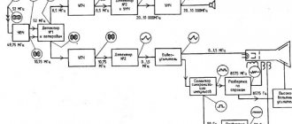
Modern electric machines have a wide variety of designs and can implement different types of voltage and current, as well as different types of motion - rotational, oscillatory, linear, etc. The power range of modern electric machines is 10-17 - 109 W. Figure 1 shows the distribution areas and areas of use of capacitive (graph 1), inductive-capacitive (graph 2) and inductive (graph 3) electrical machines. An electric machine is a very economical energy converter.
Figure 1 – Areas of distribution of electrical machines
To control modern electrical machines, complex electronic systems are used, which are structurally combined with an electromechanical converter and form the so-called electromechanotronic system, which acts as a single technical complex. All this significantly expands the functionality of electric machines and ensures their widespread implementation in all spheres of industrial and household activities of mankind [1].
Classification by purpose
Electrical machines according to their purpose are divided into:
- Electric machine generators . They convert mechanical energy (rotation) into electrical energy. They are installed in power plants, cars, airplanes, diesel locomotives, mobile power plants, ships and other installations. In power plants, the generator is driven by powerful steam turbines; in cars, diesel locomotives and other vehicles - by gas turbines or internal combustion engines. Generators are very often used as power sources in various communications installations, automation and measuring equipment, and in other systems.
- Electric motors perform the opposite functions of a generator, namely, they convert electrical energy into mechanical energy. They are used to drive many installations in industry, agriculture, transport, everyday life, and communication systems. In automatic control systems they are actively used as regulatory, programming and executive bodies.
- Electrical machine converters – perform transformations of electrical quantities. For example, they can convert direct current into alternating current and vice versa, change the frequency, number of phases and other functions. In connection with the active introduction of semiconductor converters, electric machine converters are used extremely rarely (almost never) in new projects, and already installed electric machine converters are actively modernized with semiconductor ones (thyristor and transistor).
- Electric machine compensators – regulate the power factor cos φ, namely the balance of reactive power in the network.
- Electric machine amplifiers - used for high power objects. These are a kind of amplifiers; they amplify high-power signals, while control is carried out by low-power signals. The role of these amplifiers, as well as electrical machine compensators, in the modern world is practically eliminated due to the use of semiconductor amplifiers (transistor and thyristor).
- Electromechanical signal converters are, as a rule, electrical micromachines (for example, selsyns), which are quite widely used in automatic control systems.
Fundamental laws of electromechanical energy conversion in inductive machines
Ampere's law
According to Ampere's law, a force acts on a current-carrying conductor in a magnetic field
- where F
– force, N, - I
– current strength, A, - – conductor length, m,
- B
—magnetic induction, T, - — angle between the direction of the current and the magnetic induction vector, degrees.
The direction of this force is determined by the “left hand” rule.
Faraday's law of electromagnetic induction
The discovery of electromagnetic induction in 1831 by Faraday is one of the fundamental discoveries in electrodynamics. Maxwell owns the following in-depth formulation of the law of electromagnetic induction:
Any change in the magnetic field over time excites an electric field in the surrounding space. The circulation of the strength vector E of this field along any fixed closed contour s is determined by the expression [3] [4]
,
- where E – electric field strength, V/m,
- ds – contour element, m,
- Ф - magnetic flux, Wb,
- t—time, s
The electromotive force of induction arising in a closed loop is equal to the rate of change in time of the flux of magnetic induction
,
- where is the electromotive force of induction, V
The “-” sign shows that the induced current arising in a closed conducting circuit has such a direction that the magnetic field it creates counteracts the change in the magnetic flux that caused the current.
Rotating electric machines
Rotating electric machine
- an electrical device intended for energy conversion based on electromagnetic induction and the interaction of a magnetic field with an electric current, containing at least two parts participating in the main conversion process and having the ability to rotate or rotate relative to each other [2].
DC Rotating Machine
, or direct current machine, is a rotating electrical machine in which the main energy conversion process is determined by consuming or generating only direct electric current.
AC Rotating Machine
- a rotating electrical machine, the main energy conversion process in which is determined by the consumption or generation of alternating electric current.
DESIGN AND MANUFACTURE OF WINDINGS
Electrical machines
In modern electric machines, cylindrical opposite-pole (drum) windings are most widespread. The conductors of such windings are located along the air gap of the machine and do not cover the magnetic circuits of the stator and rotor. Other types of windings are found only in some special types of electrical machines [6].
TYPES OF WINDINGS AND THEIR INSULATION
Windings can be concentrated or distributed. In lumped windings, the turns that form a pole are combined into one, usually multi-turn coil, which is mounted on a ferromagnetic core. The pole formed by the coil and cores is called salient.
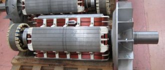
The concentrated windings of the poles of direct and alternating current machines are identical in connection diagrams and differ from each other only in the design features and methods of fastening the coils. The field windings of almost all DC machines are concentrated. In AC machines, the excitation windings of synchronous machines with a rotation speed of no more than 1500 rpm are lumped. Such machines are called machines with salient poles on the rotor or machines with salient pole rotors (Fig. 3.1).
Rice. 3.1. rotors of synchronous machines with salient poles:
A -
multi-pole;
b -
four-pole
Distributed windings consist of coils with a relatively small number of turns each (in high-power machines - up to one or two turns per coil). The coils are placed evenly along the entire circumference of the air gap in the slots of the stator or rotor (Fig. 3.2). The coils connected to each other according to a certain pattern form the so-called implicit poles of the machine.
Rice. 3.2. AC machine stator Fig. 3.3. Distributed coils
with distributed rectangular wire winding:
A -
subdivided;
b
- solid;
1
— groove parts;
2 —
frontal parts;
3
- output ends
Distributed windings are used in the stators and phase rotors of asynchronous machines, in the stators of synchronous machines, armatures of DC machines and in the rotors of synchronous machines with a rotation speed of 3000 rpm (in non-salient pole rotors). In a number of designs of DC machines, the excitation windings are also distributed.
The distributed winding coils (Fig. 3.3) are wound with winding wire. The straight parts of the turns located in the grooves of the magnetic circuit are called groove parts; curved ones, which connect the grooved parts to each other - with the frontal parts of the coil. Similar names - groove and frontal parts - have the corresponding parts of the reel. The bending areas of the frontal parts are called the heads of the coils, the beginnings and ends of the winding wire with which the coil is wound are called the output ends of the coil.
The sides of the coils of distributed windings can occupy either a whole slot or only half (Fig. 3.4). In the first case, the winding is called single-layer, in the second - two-layer, since the sides of the coils are placed in grooves in two layers: one in the lower half of the groove - the lower layer, the second in the upper half - the upper layer.
| Rice. 3.4. Cross-section of semi-closed stator slots with a round wire winding: a - low-power machines, single-layer winding; b - medium power machines, two-layer winding | Rice. 3.5. Schematic representation of the elements of coil windings: a - loop; b - wave, rod winding; c - loop; g - wave |
Some types of windings are made not from coils, but from rods - rod winding (Fig. 3.5). Each rod is like a coil, cut in half along the frontal parts, and consists of one groove and two halves of different frontal parts. The turns of the rod winding are formed after the winding is laid in the grooves and the heads of the rods are connected to each other. In calculations and diagrams, the rod winding is considered as a coil winding with one turn in the coil.
Based on the direction of bending of the frontal parts of the coils or rods, which determines the sequence of their connections to each other, loop and wave windings are distinguished (see Fig. 3.5).
Almost all windings of electrical machines are wound with insulated winding wire. Much less often, uninsulated rectangular wire or copper bars are used for windings, onto which insulation is applied during the manufacturing process of the coils. Only the short-circuited windings of the rotors of asynchronous motors and the damper or starting windings of synchronous machines do not have insulation. The rods of these windings are installed in non-insulated grooves of the magnetic circuit, and in most asynchronous motors with power up to 300...400 kW they are performed by pouring aluminum or its alloys into the grooves.
A number of requirements are imposed on the insulation of electrical machines, the purpose of which is to ensure reliable operation of the machine throughout its entire design life. The insulation, first of all, must have sufficient electrical strength to prevent possible short-circuiting of the winding turns to metal parts of the machine or to each other. To meet this requirement, the insulation must have good thermal conductivity, since otherwise the heat generated in the winding conductors will heat it above permissible limits, and the electrical strength of the insulation will be reduced. In addition, the insulation of the windings should not noticeably deteriorate its electrical properties under the influence of mechanical forces to which it is exposed during the process of laying the windings in the grooves, as well as during operation of the machine, under the influence of moisture, oil vapors and various gases that the air surrounding the machine may contain. These requirements determine the thermal and mechanical strength, moisture and oil resistance, etc. required for insulation.
According to its functional purpose, winding insulation is divided into body insulation - external insulation of coils, isolating them from the walls of the grooves in the cores (slot insulation) and from other metal parts of the machine (insulation of the frontal parts of the coils); interphase, isolating the coils of each phase of the winding from other phases; turn, isolating each turn of the coil from other turns; conductor - insulation of each of the winding conductors. Each type of insulation has its own specific design and is subject to different requirements.
In general, the thickness and design of all types of insulation are determined by its functional purpose, the rated voltage level of the machine, its type and the operating conditions for which the machine is intended.
The housing insulation of the groove parts of the winding coils is subject to the most severe operating conditions. The limited dimensions of the groove lead to the need to perform groove insulation in the form of a thin and mechanically strong layer that meets all the above requirements for the insulation of electrical machines, i.e., electrical and mechanical strength, thermal conductivity, etc. Modern electrical insulating materials make it possible to perform groove insulation of machines with a nominal voltage up to 660 V with a thickness not exceeding a few tenths of a millimeter per side, and high rated voltage machines with a thickness not exceeding a few millimeters per side.
Body insulation can be either continuous or sleeve insulation by design. Continuous insulation is formed by wrapping the coil conductors along their entire length with a tape of insulating material, such as mica tape, glass tape, or glass mica tape. The tape is usually applied half-overlapping (full overlap) in several layers, the number of which depends on the rated voltage of the machine. In most cases of structures, after applying the tape, the insulation is impregnated with insulating compounds - varnishes or compounds to create a monolithic insulating layer and increase its thermal conductivity and mechanical strength.
Sleeve insulation is formed by wrapping the straight grooved parts of the coils with a wide sheet of insulating material, followed by hot rolling of the applied layers (soft sleeve) or hot rolling, crimping and baking (hard sleeve). Continuous tape insulation is applied to the curved frontal parts of sleeve-insulated coils.
Continuous and sleeve insulation is used for the windings of all machines with a voltage of 3000 V and above, in the armature windings of high-power DC machines, the rod wave windings of phase rotors of asynchronous motors, as well as in special machines, for example, moisture-resistant designs at any rated voltage.
The slotted parts of the windings of machines with voltages up to 600 V are insulated with boxes made of one or two layers of insulating material - film synthetic cardboard, electronite, imidoflex, etc. The slotted boxes are installed in the slots before laying the winding. They cannot serve as reliable housing insulation for the windings of higher voltage machines.
Examples of winding insulation are given in the description of specific winding designs.
Table 3.10. Insulation of coil windings of phase rotors of asynchronous motors with power up to 100 kW, heat resistance class B
| Winding part | Position in the picture | Material | Number of layers | Double-sided insulation thickness, mm | |||
| Name | Brand | Thickness, mm | in width | in height | in width | in height | |
| Pazovaya | Swelling of insulation due to varnish application | — | — | — | — | 0,1 | 0,1 |
| 1 | Glass tape | LES | 0,1 | 1 layer staggered | 0,2 | 0,2 | |
| Just one reel | — | — | — | — | 0,3 | 0,3 | |
| 2 | Fiberglass fabric | LSB | 0,2 | 0,4 | 0,6 | ||
| 3 | Flexible micanite | GFS | 0,2 | 0,4 | 0,6 | ||
| 4 | Fiberglass fabric | LSB | 0,2 | 0,4 | 0,6 | ||
| 5 | Fiberglass | ST | 0,5 | — | — | 0,5 | |
| 6 | Same | ST | 0,5 | — | — | 0,5 | |
| 7 | « | ST | 0,5 | — | — | 0,5 | |
| Laying tolerance | — | — | — | — | 0,5 | 0,8 | |
| Total per groove without wedge | — | — | — | — | 4,7 |
Continuation of Table 3.10
| Winding part | Position in the figure | Material | Number of layers | Double-sided insulation thickness, mm | ||||
| Name | Brand | Thickness, mm | in width | in height | in width | in height | ||
| Frontal | Middle coils in a coil group | 8 | Glass tape | LES | 0,2 | 1 full overlap layer | 0,8 | 0,8 |
| Outer coils in a coil group | 9 | Fiberglass fabric | LSB | 0,2 | 1 full overlap layer | 0,8 | 0,8 | |
| 10 | Glass tape | LES | 0,2 | 1 full overlap layer | 0,8 | 0,8 | ||
| Insulation thickness of outer coils | — | — | — | — | 1,6 | 1,6 |
Rod windings of phase rotors of asynchronous motors are used in machines with a power of more than 100 kW, and in some versions - starting with a power of 40...50 kW. The windings are made of rectangular busbar copper. The mechanical rigidity of the rods makes it possible to make the rotor slots semi-closed with a narrow slot, which helps improve the performance of the engines. The rods are inserted into the grooves from the end of the rotor, so only one front part of the rod is bent before installation. The second frontal part is bent after installing the rod in place in the groove [2].
The insulation design of the rotor rod windings is given in Table. 3.11. This table gives two values for the number of layers and insulation thickness depending on the voltage on the rotor slip rings, which is determined by the winding data of the machine.
Sleeves for rotor rods are made from micafolia, steklomicafolium or from sheet materials based on micafolia: micafolia, glass micafolia. Thermosetting varnishes are used as binders for the manufacture of cartridges. The frontal parts of the rods are insulated with tape materials. The electrically weak point in the insulation of rotor rods, as well as in the coil windings of stators with sleeve insulation, is the junction of two types of insulation - sleeve on the groove part and continuous on the front.
Table 3.11. Insulation of rod windings of phase rotors of asynchronous motors with a rotation axis height ≥ 280 mm
| Winding part | Position in the picture | Material | Voltage up to 750 V | Voltage up to 1200 V | ||||||||||
| Name, brand | Thickness, mm | Number of layers | Double-sided insulation thickness, mm | Number of layers | Double-sided insulation thickness, mm | |||||||||
| Heat resistance class | Heat resistance class | Heat resistance class | in width | in height | Heat resistance class | in width | in height | |||||||
| B | F | H | B | F and H | B | F and H | B | F and H | ||||||
| Pazovaya | 1 | Glass mica plastifolium IFG-B | Synthofolium - F | Synthofolium - H | 0,15 | 0,16 | 4.5* turns | 3.5 turns | 1,1 | 2,2 | 9.5* turns | 7.5 turns | 2,4 | 4,5 |
| Fiberglass fabric | ||||||||||||||
| 2 | LSB-105/120 | LSP-130/155 | LSK-155/180 | 0,15 | 0,3 | 0,3 | 0,3 | 0,3 | ||||||
| Fiberglass | ||||||||||||||
| 3 | ST | STEF-1 | STK | 0,5 | — | 0,5 | — | 0,5 | ||||||
| 4 | ST | STEF-1 | STK | 0,5 | — | 0,5 | — | 0,5 | ||||||
| 5 | ST | STEF-1 | STK | 0,5 | — | 0,5 | — | 0,5 | ||||||
| Tolerance for winding installation | — | — | 0,3 | 0,5 | — | — | 0,3 | 0,5 | ||||||
| Total insulation thickness in groove (without wedge) | — | 1,7 | 4,5 | — | — | 6,6 | ||||||||
| Frontal | 6 | Glass mica tape LS-PE-934-TP | Polyimide film 0.05 3 = 0.15 | 0,15 | 1 full overlap layer | 0,6 | 0,6 | 2 full overlap layers | 1,2 | 1,2 | ||||
| 7 | Glass tape LES | 0,1 | 1 full overlap layer | 0,4 | 0,4 | 2 full overlap layers | 0,8 | 0,8 | ||||||
| Total thickness of the rod insulation in the front part | 1,0 | 1,0 | 2,0 | 2,0 |
* Taking into account shrinkage of 15...20%
In order to increase the electrical strength of the insulation of this section, it is insulated with a gradual transition from sleeve to continuous insulation using the cone or reverse cone type.
The insulation of phase rotor rods for motors of some standard sizes is made of continuous strip material along the entire length of the rod, followed by crimping and baking of the insulation in hot presses.
Short-circuited windings. Squirrel-cage windings are widely used in the rotors of asynchronous motors. They are also used as dampers and starters in the rotors of synchronous machines.
Their main difference from all other windings of electrical machines is the lack of insulation between the groove part of the winding and the walls of the groove. The sometimes encountered phase-isolated and short-circuited windings of the rotors of special-design asynchronous machines are not considered here.
The short-circuited windings of the rotors of asynchronous motors are divided into two types according to design and manufacturing technology: welded and cast (Fig. 3.10).
Damper and starting windings of synchronous machines are made only of welded construction. In the vast majority of cases, the winding rods have a round cross-section and are placed in the grooves of the pole pieces.
The damper windings of synchronous motors are more powerful than synchronous generators, since they are used in the same way as starting ones. Generators have damper windings made of copper. In engines, brass is often used to improve starting characteristics.
Rice. 3.10. Squirrel cage rotors of asynchronous motors:
- with insert rods; - with cast winding;
1
- winding rods;
2
— closing rings;
3
- ventilation blades
GROOVE FILLING COEFFICIENT
The toothed zone is the most magnetically stressed section of the magnetic circuit; therefore, when designing machines, they strive to choose the smallest dimensions of the grooves that ensure the placement of the required number of conductors and insulation in them. The degree of use of the groove volume to accommodate winding copper is estimated by the groove filling coefficient with copper, which is the ratio of the total cross-sectional area of all conductors in the groove to the cross-sectional area of the groove “in the clear”:
, (3.1)
where q
el
is
the cross-sectional area of an elementary conductor;
n
el—number of elementary conductors in one effective one;
u
p is the number of effective conductors in the slot.
Factor k
m depends on the total amount of insulation in the groove, i.e. on the thickness of the body, turn and conductor insulation and the presence of various insulating spacers. As the insulation thickness increases, for example in machines with higher voltage ratings or when inferior insulating materials are used, the copper fill factor of the groove decreases. This leads to deterioration in the use of the groove space, and consequently, the entire tooth zone of the machine.
Average values for modern electrical machines, depending on the rated voltage and type of windings, are given in table. 3.12.
Table 3.12. Average values of groove fill factor with copper
| Winding type | Coefficient |
| Windings made of round wire with enamel insulation for voltages up to 660 V | 0,3 |
| Windings made of rectangular wire for a voltage of 3000 V (wire brand PSD) | 0,22…0,37 |
| Rectangular wire windings for voltage 6000 V | 0,14…0,25 |
For a machine with windings of rectangular wires, it can be calculated quite accurately, since during design the location of each conductor in the groove is determined in advance.
In round wire windings, the position of each conductor in the slot cannot be determined in advance. In addition, the density of conductors in the slot is not constant. It depends on the forces applied by the wrapper when compacting the conductors as they are laid in the grooves. Experience has established that with an excessively high packing density of round wires, the labor intensity of winding work unjustifiably increases, and the reliability of the winding sharply deteriorates due to the resulting mechanical damage to the conductor insulation.
The density of laying conductors in the grooves is estimated by the technological coefficient of filling with conductors of the insulation-free cross-sectional area of the groove:
. (3.2)
The numerator of this expression is the product of the area of the square described around an insulated elementary conductor with a diameter by the number of all elementary conductors in the groove, and the denominator is the cross-sectional area of the groove free from insulation, i.e., the area in which the winding conductors are located. The coefficient is usually called the slot fill factor. It characterizes only the manufacturability of laying a winding from a round wire, and not the extent to which the volume of the groove is used to accommodate the winding conductors. So, with the same winding density, it will be the same for the windings of machines with different thicknesses of slot or conductor insulation, with double-layer or single-layer windings, etc.
In modern electrical engineering, the density of the winding is sought to be in the range of 0.7...0.75, with lower values in machines with the number of poles equal to two.
It should be noted that an increase in the number of elementary conductors in one effective conductor, i.e., the use of a winding wire of a smaller diameter with the same effective conductor area, leads to a slight increase in the fill factor, and vice versa. This is explained by the fact that the thickness of the winding wire insulation remains constant with relatively large changes in the diameter of the round winding wires (see Appendix P3).
DIAGRAM ELEMENTS AND SYMBOLS
TERMINALS OF THREE-PHASE WINDINGS
The main element of the winding of an electric machine is the coil. Several series-connected turns, located in the same slots, are combined with each other by common body insulation, resulting in the formation of a winding coil. Each side of the coil is placed in one groove. If the entire groove is occupied by the side of only one coil (the sides of the coils are arranged in one layer), then the winding is called single-layer. If the sides of two coils are placed in each slot, one above the other, then the winding is called two-layer.
Several series connected in adjacent grooves form a coil group, which is a winding of a pole or a pair of poles of one of the phases of the machine. The number of coils in a coil group is denoted by q.
Since
q
coils are placed in adjacent slots, the same sides of these coils occupy
q
slots, forming the winding of the pole of one phase of the machine.
In one coil group, all coils can only be connected in series, since the EMF vectors of the coils located in different slots are shifted relative to each other by the slot angle, and when connected in parallel, large equalizing currents arise. Parallel connection of coils in one group is used in some windings of large two-pole turbogenerators.
Several interconnected coil groups form a winding phase. Coil groups in phase are connected in series, parallel or mixed, series-parallel. The number of coil groups in each phase depends on the number of poles and the type of winding. The number of parallel branches when connecting coil groups is determined when calculating the windings.
In most cases, the ends of the phases are not connected inside the machine, but all the beginnings and all ends of the phases are brought to the terminal box terminals, which allows the machines to be switched on to two mains voltages, connecting the phases in a star or triangle. The voltage per phase of the stator winding does not change.
| Image of a winding diagram. The order of connecting individual coils, coil groups and winding phases to each other is specified in the technical documentation in the form of a drawing, which is called a winding diagram. When drawing diagrams, a number of conventions are adopted: a drawing depicting a winding diagram is not drawn to scale and does not reflect any relationship between the dimensions of the machine and the winding and its parts; each coil is represented by one line, regardless of the number of turns in it and the elementary conductors in each effective conductor; all coils are depicted in the same plane, etc. | Rice. 3.11. End diagram of a single-layer concentric winding z = 24, 2р = 4, а = 1 |
There are several known ways of depicting circuits, of which the most widespread are the so-called expanded and end circuits. The end diagram is a kind of end view of the wound core (Fig. 3.11). It clearly shows the positions of the frontal parts of the coils, but there is not enough space to depict inter-coil and inter-group connections, which is inconvenient in complex circuits with several parallel branches.
Expanded diagrams represent a development of a stator or rotor with a winding and allow you to show all the connections between the winding elements - coils and coil groups.
Phase zone. The sides of the coils of one coil group are distributed in q
slots lying one behind the other.
In a symmetrical m-phase winding, at each pole division of such groups there will be m with q
slots in each.
Consequently, the sides of the coils belonging to the same phase are located at each pole division τ in grooves occupying the 1/mth part of it, or the [π D
/(2рm)
=
τ/m]th part of the gap circumference, called the phase zone. In the windings of three-phase machines built according to this principle, the phase zone occupies an arc of a circle containing an electrical angle τ/m = 180°/3 = 60°, therefore such windings are called windings with a 60-degree phase zone.
Sometimes windings are used in which m q
The grooves are located on two pole divisions. The phase zone of such windings occupies the 2τ/mth part of the circle, which corresponds to an electrical angle of 120° in three-phase machines. Such windings are called windings with a 120-degree phase zone.
Most three-phase general purpose machines use windings with a 60-degree phase zone. However, there are also machines with windings that have a 120-degree phase zone. For example, in multi-speed induction motors with a pole-switching winding, when switched on to a larger number of poles, the winding has a 60-degree phase zone, and when switched on to work with a smaller number of poles, it has a 120-degree phase zone.
The most common winding designs with a 60-degree phase zone are discussed below. Fundamentally, winding circuits with a 120-degree phase zone do not differ from those discussed below, however, when compiling them and calculating winding coefficients, it is necessary to take into account the features of this type of winding.
Designation of winding terminals of three-phase machines. Currently, there are two systems for designating the terminals of the windings of electrical machines. One of them, established by GOST 183-74, is retained for machines developed before 1987 and modernized. The terminals of the windings of these machines are designated by the letters of the Russian alphabet: stator windings - C, rotor windings of asynchronous motors - P, excitation windings of synchronous machines - I. The numbers after the letters indicate the beginnings and ends of the phases: the first phase is 1 and 4, respectively, the second phase is 2 and 5, third phases 3 and 6. In table. 3.13 shows the designations established by GOST 183-74 depending on the number of terminals and the winding connection diagram. Designations must be applied directly to the ends of the terminals: on cable lugs, bus ends or special crimps tightly fixed to the terminals.
Table 3.13. Designations of winding terminals for AC electrical machines developed before 1987 and being modernized (GOST 183 - 74)
| Name and connection diagram of the winding | Number of pins | Name of phase or output | Pin designation |
| Start | end | ||
| Stator winding: Open circuit | First phase | C1 | C4 |
| Second phase | C2 | C5 | |
| Third phase | C3 | C6 | |
| Star connection | 3 or 4 | First phase | C1 |
| Second phase | C2 | ||
| Third phase | C3 | ||
| Zero point | |||
| Delta connection | First conclusion | C1 | |
| Second conclusion | C2 | ||
| Third conclusion | C3 | ||
| Excitation winding (inductors) of synchronous machines | I1 | AND 2 | |
| Wound rotor winding of asynchronous motors | First phase | P1 | |
| Second phase | P2 | ||
| Third phase | P3 |
Continuation of the table. 3.13
| Name and connection diagram of the winding | Number of pins | Name of phase or output | Pin designation |
| Star circuit | First phase | P1 | |
| Second phase | P2 | ||
| Third phase | P3 |
Notes: 1. In the drawings of electrical circuits for connecting windings with 6 output ends (in the drawings on the free field of the diagram), it is allowed to use double designations (C1C6; C2C4; C3C5) when connecting phases in a triangle and triple designation (C4C5C6) for the star point (zero point) when connecting phases into a star.
2. The terminals of composite and sectional stator windings of machines should be designated by the same letters as simple windings, but with additional numbers in front of the letters. For example, the conclusions of the first winding (first section) of the first phase; beginning 1C1, end 1C4, conclusions of the second winding (section) of the first phase: beginning 2C1, end 2C4.
3. The contact rings of the rotor of asynchronous motors are also designated as the rotor winding terminals connected to them, and the arrangement of the rings should be in the order of the numbers indicated in the table, and ring 1, connected to terminal P1, should be the farthest from the rotor winding.
In small machines, in which alphanumeric designations are difficult due to lack of space, GOST allows the use of color designations (Table 3.14) with wires with multi-colored insulation, paints, etc.
Table 3.14. Color designation of stator winding terminals of three-phase alternating current machines
| Winding connection diagram | Number of pins | Name of phase or output | Pin color code | |
| Start | end | |||
| Open circuit | First phase | Yellow | Yellow with black | |
| Second phase | Green | Green with black | ||
| Third phase | Red | Red with black | ||
| Star | 3 or 4 | First phase | Yellow | — |
| Second phase | Green | — | ||
| Third phase | Red | — | ||
| Zero point | Black | — | ||
| Triangle | First conclusion | Yellow | — | |
| Second conclusion | Green | — | ||
| Third conclusion | Red | — |
For machines developed after January 1, 1987, a designation system for winding terminals has been established (GOST 26772-85), which complies with international standards. According to this system (Table 3.15), the conclusions are designated by letters of the Latin alphabet: the first phase of the stator winding - by the letter U ,
the second phase - the letter V
,
the third phase - the letter W
;
the rotor winding terminals according to the phases are marked with the letters K, L and M
;
synchronous
machines - letter F. The beginnings and ends of the phases are indicated respectively
by
the numbers 1 and 2
,
located after the letters. If there are intermediate terminals, they are designated by a letter defining the phase and subsequent numbers: 3, 4, etc.
Table 3.15. Designation of winding terminals for AC electrical machines developed after January 1, 1987 (GOST 26772-85)
| Name and connection diagram of the winding | Number of pins | Name of phase or output | Pin designation | |
| Start | end | |||
| Stator winding: | ||||
| open circuit | First phase | UI | U2 | |
| Second phase | V1 | V2 | ||
| Third phase | Wl | W2 | ||
| star connection | 3 or 4 | First phase | U | |
| Second phase | V | |||
| Third phase | W | |||
| Star point | N | |||
| triangle connection | First conclusion | U | ||
| Second conclusion | V | |||
| Third conclusion | W | |||
| sectional winding | First phase | U1 | U2 | |
| Conclusions from the first phase | U3 | U4 | ||
| Second phase | VI | V2 | ||
| Conclusions from the second phase | V3 | V4 | ||
| Third phase | WI | W2 | ||
| Conclusions from the third phase | W3 | W4 | ||
| split windings designed for series or parallel connection | — | First phase | U1 | U2 |
| U5 | U6 | |||
| Second phase | VI | V2 | ||
| V5 | V6 | |||
| Third phase | W1 | W2 | ||
| W5 | W6 | |||
| separate windings designed for series or parallel connection | _ | First phase | 1U1 | 1U2 |
| 2U1 | 2U2 | |||
| Second phase | 1V1 | 1V2 | ||
| 2VI | 2V2 | |||
| Third phase | IW1 | IW2 | ||
| 2WI | 2W2 | |||
| Winding of a phase rotor of an asynchronous motor: | ||||
| open circuit | First phase | KI | K2 | |
| Second phase | L1 | L2 | ||
| Third phase | Ml | M2 | ||
| star connection | 3 or 4 | First phase | TO | |
| Second phase | L | |||
| Third phase | M | |||
| Star point | Q | |||
| triangle connection | First conclusion | K | ||
| Second conclusion | L | |||
| Third conclusion | M | |||
| Excitation winding of synchronous machines | — | F1 | F2 |
The color designations of winding terminals for machines in which alphanumeric designations are difficult are kept the same as with the previous system
Types of rotating electrical machines
By the nature of the magnetic field in the main air gap
Single pole machine
- a rotating electric machine in which the normal component of magnetic induction at all points of the main air gap has the same sign.
Opposite pole machine
- a rotating electric machine in which the normal component of magnetic induction in different parts of the main air gap has different signs.
salient pole machine
- an opposite-pole machine in which the poles protrude towards the main air gap.
Non-salient pole machine
- opposite-pole machine with a uniform main air gap.