Regulations
Taking into account the large number of electrical elements, a number of normative documents have been developed for their alphanumeric (hereinafter referred to as BO) and conventional graphic designations (UGO) to eliminate discrepancies. Below is a table showing the main standards.
Table 1. Standards for graphic designation of individual elements in installation and circuit diagrams.
| GOST number | Short description |
| 2.710 81 | This document contains GOST requirements for BO of various types of electrical elements, including electrical appliances. |
| 2.747 68 | Requirements for the dimensions of displaying elements in graphical form. |
| 21.614 88 | Accepted codes for electrical and wiring plans. |
| 2.755 87 | Display of switching devices and contact connections on diagrams |
| 2.756 76 | Standards for sensing parts of electromechanical equipment. |
| 2.709 89 | This standard regulates the standards in accordance with which contact connections and wires are indicated on diagrams. |
| 21.404 85 | Schematic symbols for equipment used in automation systems |
It should be taken into account that the element base changes over time, and accordingly changes are made to regulatory documents, although this process is more inert. Let's give a simple example: RCDs and automatic circuit breakers have been widely used in Russia for more than a decade, but there is still no single standard according to GOST 2.755-87 for these devices, unlike circuit breakers. It is quite possible that this issue will be resolved in the near future. To keep abreast of such innovations, professionals monitor changes in regulatory documents; amateurs do not have to do this; it is enough to know the decoding of the main symbols.
Types of electrical circuits
In accordance with ESKD standards, diagrams mean graphic documents on which, using accepted notations, the main elements or components of a structure, as well as the connections connecting them, are displayed. According to the accepted classification, there are ten types of circuits, of which three are most often used in electrical engineering:
- Functional, it shows the node elements (depicted as rectangles), as well as the communication lines connecting them. A characteristic feature of this scheme is minimal detail. To describe the main functions of nodes, the rectangles displaying them are signed with standard letter designations. These can be various parts of the product that differ in functionality, for example, an automatic dimmer with a photo relay as a sensor or a regular TV. An example of such a scheme is presented below.
Example of a functional diagram of a television receiver - Fundamental. This type of graphic document displays in detail both the elements used in the design and their connections and contacts. The electrical parameters of some elements can be displayed directly in the document, or presented separately in the form of a table.
Example of a circuit diagram of a milling machine
Parallel motors
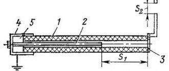
Direct current machines are designated in accordance with GOST. Salient-pole mechanisms with one or more AC windings are shown in the drawings as two circles (one inside the other).
Cables are connected to the outer and inner circles (in proportion to the moving part - the rotor, and the stationary part - the stator).
There are cases when the field winding is made according to the “equilateral triangle” principle, then the graphic designation will look like this.
Graphic symbols
Each type of graphic document has its own designations, regulated by relevant regulatory documents. Let us give as an example the basic graphic symbols for different types of electrical circuits.
Examples of UGO in functional diagrams
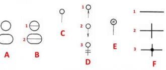
Below is a picture depicting the main components of automation systems.
Examples of symbols for electrical appliances and automation equipment in accordance with GOST 21.404-85
Description of symbols:
- A – Basic (1) and acceptable (2) images of devices that are installed outside the electrical panel or junction box.
- B - The same as point A, except that the elements are located on the remote control or electrical panel.
- C – Display of actuators (AM).
- D – Influence of MI on the regulating body (hereinafter referred to as RO) when the power is turned off:
- RO opening occurs
- Closing RO
- The position of the RO remains unchanged.
- E - IM, on which a manual drive is additionally installed. This symbol may be used for any RO provisions specified in paragraph D.
- F- Accepted mappings of communication lines:
- General.
- There is no connection at the intersection.
- The presence of a connection at the intersection.
UGO in single-line and complete electrical circuits
There are several groups of symbols for these schemes; we present the most common of them. To obtain complete information, you must refer to the regulatory documents; the numbers of state standards will be given for each group.
Graphic designation of electrical elements on the GOST diagram
Drawings and diagrams of electrical installations are needed for reading by electricians and electricians. The technical document contains schematic information about the size, shape, and composition of electrical equipment. To read, you need to know the common symbols on electrical diagrams that are used to show switches, circuit breakers, motors, rectifiers and other electrical elements in the drawing.
- Types of electrical circuits
- Graphic symbols
- Letter designations
Types of electrical circuits
An electrical diagram is a technical drawing drawn up using symbols used for conventional parts of equipment. The decoding gives an idea of the set of elements in the circuit and the interaction between them. To designate the diagram itself, unlike other drawings, the letter E is used. The rules for decoding are given in GOST 2.702 - 2011 and GOST 2.708 - 81.
Types of electrical circuits:
- Structural. They are compiled during the design process and display the main components of the system (electrical wiring lines, transformers, distribution nodes). This type gives a general idea of the operation of the installation.
- Functional. They contain general diagrams showing the relationship between the components of the object, revealing the essence of the electrical installation. The standards in these schemes are conditional; general standards for the preparation of technological documents are applicable.
- Principled. Shows all magnetic, electrical and electromagnetic connections between elements, characteristics of components. For these schemes there are many standards regarding design and symbols on the drawings.
- Assembly. The drawings contain information about the location of elements outside and inside the installation. Using graphic images, equipment can be manufactured taking into account their correct interaction. General designation requirements apply.
Graphic symbols
Any electrical installation operates under certain conditions, for which symbols have been developed in electrical diagrams.
When reading the drawings, you can obtain the following information:
- conditions for using electrical equipment;
- correspondence between design and real circumstances;
- find unnecessary conditions and evaluate the consequences of their action.
For reading, they use the technique of dividing an electrical circuit into separate circuits and examining them. The simplest schemes are subsequently considered in combination.
Simple circuits include the elements:
- source of electric current: secondary transformer winding, battery, capacitor, etc.;
- current receiver: lamps, motors, relays, rarefied capacitors;
- return conductor: from the point of analysis to the primary source of current;
- one switching terminal: machine, switch.
Read diagrams using symbols to identify electrical elements on the diagrams. Graphic figures are formed from rectangles, squares, circles, solid and dashed lines, dots, vectors. They are combined in a drawing according to developed standard standards, so you can easily display electrical devices, electrical machines, mechanical and electrical connections, and other combinations and interactions.
In addition to symbols, special graphics are used to show the functionality of the module. For example, for a contact they put an image of closing or opening. There are additional figures on the moving parts to help you find the relay, RCD, and control buttons.
Some parts and assemblies are shown with several variants of graphic icons . For example, this applies to transformer windings or switching contacts. You can use all these options in different cases.
If the standard does not provide an icon for designation , it is created based on the fundamental action of the element. They take into account the signs for similar types of equipment and modules, and pay attention to the principle of constructing the symbols provided for by the standards.
To symbolize electrical boxes, cabinets, panels, control panels on electrical diagrams, the following icons are used:
Sockets, panels, and circuit breakers received the following signs:
Lighting elements, lamps are indicated in accordance with GOST:
In complex circuits of electrical equipment the following signs are used:
To show chokes and transformers on circuit diagrams, there are graphic images:
Measuring modules are depicted graphically:
For electricians, they show grounding loops and power cables :
The diagrams contain straight and wavy lines, “+” and “-” icons, showing current pulses, type and voltage:
Contact connections are indicated graphically as follows:
Elements in radio circuits are depicted as follows:
Such graphic elements are used to show all components, nodes, and modules in a circuit. There are many of them, it’s difficult to remember, but you can always refer to specialized electrician reference books.
Letter designations
In single-line electrical diagrams, letters are used to understand the configuration of the network.
Their use is regulated by GOST 76.24 – 55:
- electric relays of voltage, current, resistance, power, intermediate, temporary, gas, index and others have the letter designation RT, RS, RP, RU, RG, RV, RN, RTV, RM and similar;
- control button - KU;
- final breaker - HF;
- team controller - QC;
- travel switch - PV;
- head engine - DG;
- cooling pump motor - BEFORE;
- feed motor - DP;
- high speed motor - DBH;
- spindle motor - DS.
Letter codes are placed next to the element (to the right) or above it . They are combined with graphic icons. In positional letter codes of identical parts, numbers are added according to their quantity.
In domestic electrical circuits, markings are used to designate radio engineering and electrical parts:
Letter designations
In electrical diagrams, in addition to graphic symbols, alphabetic symbols are also used, since without the latter, reading the drawings will be quite problematic. Alphanumeric marking, just like UGO, is regulated by regulatory documents, for electrical this is GOST 7624 55. Below is a table with BO for the main components of electrical circuits.
Letter designations of main elements
Unfortunately, the size of this article does not allow us to provide all the correct graphic and letter symbols, but we have indicated regulatory documents from which all the missing information can be obtained. It should be taken into account that current standards may change depending on the modernization of the technical base, therefore, we recommend monitoring the release of new additions to regulations.
Electric motor winding terminals - connection diagrams
To bookmarks
Designation of stator winding terminals
Each stator of a three-phase electric motor has three coil groups (windings) - one for each phase, and each coil group has 2 terminals - the beginning and end of the winding, i.e. There are only 6 pins that are signed as follows:
- C1 (U1) is the beginning of the first winding, C4 (U2) is the end of the first winding.
- C2 (V1) is the beginning of the second winding, C5 (V2) is the end of the second winding.
- C3 (W1) is the beginning of the third winding, C6 (W2) is the end of the third winding.
Conventionally, in the diagrams, each winding is depicted as follows:
The beginnings and ends of the windings are brought out into the terminal box of the electric motor in the following order:
Depending on the connection of these terminals, such parameters of the electric motor as the supply voltage and the rated stator current change. which circuit to use to connect the electric motor windings from the passport data.
The main winding connection diagrams are triangle (denoted by Δ) and star (denoted by Y), which we will analyze in this article.
Note: In the terminal box of some electric motors you can only see three terminals - this means that the motor windings are already connected inside its stator. As a rule, the windings inside the stator are connected when repairing an electric motor (if the factory windings are burned out). In such motors, the windings are usually connected in a star configuration and are designed for connection to a 380 Volt network. To connect such a motor, you simply need to supply three phases to its three outputs.
Connection diagram of electric motor windings according to the “triangle” diagram
To connect the windings of an electric motor according to the “triangle” diagram, it is necessary: connect the end of the first winding (C4/U2) to the beginning of the second (C2/V1), the end of the second (C5/V2) to the beginning of the third (C3/W1), and the end of the third windings (C6/W2) - with the beginning of the first (C1/U1).
Conventionally, this is depicted in the diagram as follows:
Voltage is applied to terminals “A”, “B” and “C”.
In the terminal box of the electric motor, the connection of the windings according to the “triangle” diagram has the following form:
A, B, C—connection points for the power cable.
Connection diagram of electric motor windings according to the “star” scheme
To connect the windings of an electric motor in a star configuration, it is necessary to connect the ends of the windings (C4/U2, C5/V2 and C6/W2) to a common point, while voltage is applied to the beginnings of the windings (C1/U1, C2/V1 and C3/W1 ).
Conventionally, this is depicted in the diagram as follows:
In the terminal box of the electric motor, the star connection of the windings has the following form:
Definition of winding terminals
Sometimes situations arise when, after removing the cover from the terminal box of an electric motor, you are horrified to discover the following picture:
In this case, the winding terminals are not labeled, what should I do? Don't panic, this issue can be completely resolved.
The first thing to do is to divide the leads into pairs, each pair should have leads related to one winding, this is very easy to do, we will need a tester or a two-pole voltage indicator.
If using a tester, set its switch to the resistance measurement position (underlined by a red line); when using a bipolar voltage indicator, before use, it is necessary to touch the live parts under voltage for 5-10 seconds to charge it and check its functionality.
Next, you need to take any one terminal of the winding, conditionally take it as the beginning of the first winding and accordingly sign it “U1”, then touch the “U1” terminal we signed with one tester or voltage indicator probe, and touch with the second probe any other terminal from the remaining five unsigned ends. If, having touched the second terminal with the second probe, the tester readings have not changed (the tester shows one) or in the case of the voltage indicator - not a single light comes on - we leave this end and touch the other terminal of the remaining four ends with the second probe, and touch the ends with the second probe to until the tester readings change, or, in the case of a voltage indicator, until the “Test” light comes on. Having found the second terminal of our winding in this way, we accept it conditionally as the end of the first winding and sign it “U2” accordingly.
We proceed in the same way with the remaining four pins, also dividing them into pairs and signing them respectively as V1, V2 and W1, W2. You can see how this is done in the video below.
Now that all the pins are divided into pairs, it is necessary to determine the actual beginnings and ends of the windings. This can be done in two ways:
The first and simplest method is the selection method, which can be used for electric motors with a power of up to 5 kW. To do this, we take our conditional ends of the windings (U2, V2 and W2) and connect them, and briefly, preferably no more than 30 seconds, apply three-phase voltage to the conditional beginnings (U1, V1 and W1):
If the engine starts and runs normally, then the beginnings and ends of the windings are determined correctly; if the engine hums a lot and does not develop the proper speed, then there is an error somewhere. In this case, you just need to swap any two terminals of one winding, for example U1 with U2, and start again:
If the problem persists, return U1 and U2 to their places and swap the following two pins - V1 with V2:
If the engine works normally, the pins are identified correctly, the work is finished, if not, return V1 and V2 to their places and swap the remaining pins W1 with W2.
Second method: We connect the second and third windings in series, i.e. we connect together the end of the second winding with the beginning of the third (terminals V2 with W1), and apply a reduced alternating voltage (no more than 42 Volts) to the first winding to the terminals U1 and U2. In this case, voltage should also appear at terminals V1 and W2:
If voltage does not appear, then the second and third windings are connected incorrectly, in fact, two beginnings (V1 with W1) or two ends (V2 with W2) are connected together, in this case we just need to change the inscriptions on the second or third winding, for example V1 with V2. Then check the first winding in a similar way, connecting it in series with the second, and applying voltage to the third. This method is presented in the following video:
Was this article useful to you? Or maybe you still have questions ? Write in the comments!
Didn’t find an article on the website on a topic that interests you regarding electrical engineering? Write to us here. We will definitely answer you.
↑ Up
10
https://elektroshkola.ru/elektrodvigateli/vyvody-obmotok-elektrodvigatelya-sxemy-soedineniya/