Classification and designation system of digital microcircuits
Logic elements EVT
Digital microcircuits are designed to convert and process signals that vary according to the laws of a discrete function.
They are used to build digital computers, as well as digital components of measuring instruments, automatic control equipment, communications, etc. Based on their design and technological design, all digital ICs are divided into groups. Based on the nature of the functions performed in the hardware, ICs are divided into subgroups (for example, logical elements, flip-flops, etc.) and types within subgroups (for example, delay triggers The division of digital information systems into subgroups and types according to functional purpose is given in Table 1.3.1.1.
Table 1.3.1.1. Subgroups and types of ISIS
| Subgroup and type of IP | Designation |
| Circuits of arithmetic and discrete devices: | IA |
| encryptors | IV |
| decryptors | ID |
| counters | IE |
| combined | IR |
| half adders | IL |
| adders | THEM |
| other | IP |
| registers | IR |
| Logic elements | |
| AND-NOT | LA |
| AND-NOT/OR-NOT | LB |
| expanders | LD |
| OR NO | LE |
| AND | LI |
| AND-OR-NOT/AND-OR | OK |
| OR | LL |
| OR-NOT/OR | LM |
| NOT | LN |
| other | LP |
| AND-OR-NOT | LR |
| AND-OR | PM |
| Memory circuits | |
| associative memories | RA |
| permanent memory matrices | RV |
| matrices of operational storage | RM |
| permanent memories (mask) | RE |
| other | RP |
| permanent memories with the possibility of multiple electrical reprogramming | RT |
| operational memory | RU |
| permanent memories with ultraviolet erasure and electrical recording of information | RF |
| Triggers | |
| universal (type JK) | TV |
| dynamic | TD |
| combined | TK |
| Schmitt | TL |
| with delay (type D) | TM |
| other | TP |
| with separate start (RS type) | TR |
| counting (type T) | TT |
Information about the subgroup and type of microcircuit is contained in its symbol.
In accordance with GOST 17021 - 75, the designation of digital ICs must consist of four elements. The first of them is the number (1, 5, 7), indicating the IS group. It is determined by the design and technological design of the IS. The second element is two or three digits (from 00 to 99 or from 000 to 999), indicating the serial number of the development of the IC series. The third element is two letters indicating the subgroup and type of microcircuit that determine the main functional purposes of the IC (table). The fourth element is a number indicating the serial number of the IS development by functional characteristic in a given series.
The first two elements indicate the IC series. A series is understood as a set of types of ICs that can perform various functions, have a single design and technological design and are intended for joint use.
An example of a symbol for an integrated semiconductor logic chip K155LA3, representing an AND-NOT logical element with a serial development number of the series - 55, a serial number of the development of this circuit in the series according to functional characteristics - 3 is shown below (Figure 1.3.1.1.)
Figure 1.3.1.1.
If necessary, the IC developer has the right, after the serial number of the IC development according to a functional characteristic in a given series, to additionally place a letter (from A to Z), indicating the difference in the electrical parameters of the IC of the same type (for example, 531LA1P). When marking, the final letter can be replaced by a dot. Its color is indicated in the technical specifications (TS) for specific types of ICs. For microcircuits used in widely used devices, the letter K is added at the beginning of the designation (for example, K1533LAZ). As a rule, ICs with the letter K differ from microcircuits that do not have it in terms of acceptance at the manufacturer, that is, they differ not only in the temperature range at which they can be used, but also in the numerical values of some parameters.
Recently, for some IS, after the letter K an additional letter is placed, indicating a design feature (for example, KR, KM, KF).
For unpackaged ICs, the letter B is added before the digital designation of the series, and after designating the serial number of the development of the IC according to a functional characteristic in a given series (or after an additional letter designation), a number characterizing the modification of the design is indicated through a hyphen (for example, B133LA3-1). The table shows design designations for various modifications of packageless ICs.
Modification of the design of packaged integrated circuits (Table 1.3.1.2)
Table 1.3.1.2.
| Characteristics of the design of microcircuits (modification) | Design designation |
| With flexible leads With ribbon (spider) leads With rigid leads On a common plate (non-separated) Separate without loss of orientation With contact pads without leads (crystal) |
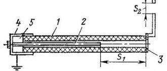
According to GOST 2.743-82, the conventional graphic designation (UGO) of a digital logic element has the shape of a rectangle, to which the lead lines are connected. The UGO of elements can contain three fields: the main one and two additional ones. Additional fields are located to the left and right of the main one. It is allowed to divide additional fields into zones, which are separated by a horizontal line. The first line of the main field contains the designation of the function performed by the element. Additional fields contain information about the functional assignments of the pins. Lead lines are characterized by a label and a pointer. The label is the name of the output. The pointer characterizes the properties of the output. The inputs of the element are depicted on the left side of the UGO, the outputs on the right side.
The dimensions of the UGO are determined by height:
— number of output lines;
— number of intervals;
— the number of lines of information in the main and additional fields;
— font size;
in width:
— the presence of additional fields;
— the number of characters placed in one line inside the UGO;
- font size.
The distance between the lead lines must be at least and a multiple of the value “C” (minimum “C” = 5 mm).
The distance between the horizontal side of the UGO, the zone boundary and the exit line must be no less than and a multiple of “C/2” (Figure 1.3.2.1.)
Figure 1.3.2.1.
The design and dimensions of the conventional graphic symbols (hereinafter referred to as UGO for brevity) of the elements must be as specified in the standards.
When drawing up a device diagram, you should adhere to the generally accepted rule: input is on the left, output is on the right
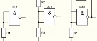
The UGIs of the elements most often found in circuit diagrams and their dimensions on a scale of 1:1 are shown in the figure. Near each element (preferably at the top or on the right) its positional designation should be indicated (R1, R2.., C1, C2, etc.). Elements must be numbered from left to right - from top to bottom, for example, like this:
R1 R4 R7 R9
R2 R5
R3 R6 R8 R10
To simplify circuits, they often use the merging of electrical communication lines into one so-called group communication line, which is depicted as a thick line. In the immediate vicinity of the entry points to the group line, they are usually numbered. Instead of numbers, you can use letter designations for signals, sometimes this makes the diagram easier to read. The minimum distance between adjacent lines extending from the group line in different directions must be at least 2 mm (on a scale of 1:1). Lines emerging from the end of the group communication line are depicted as lines of normal thickness.
UGOs of digital and analogue technology microcircuits are built on the basis of rectangles called fields. UGO of the simplest devices (for example, logical elements) consist only of the main field; in more complex ones, one or two additional ones are added to it, located on the left and right. In the main field, inscriptions and signs are placed that indicate the functional purpose of the element or microcircuit; in the additional fields, so-called labels are placed that explain the purpose of the pins. The width of the fields is determined by the number of characters (including spaces). The minimum width of the main field is 10, additional - 5 mm. The distance between the terminals, as well as between the terminal and the horizontal side of the UGO or the boundary of the zone separating some terminals from others, is 5 mm (all dimensions are on a scale of 1:1).
At the points where the output lines are connected, special signs (pointers) are depicted that characterize their special properties, a small circle (inversion), an oblique dash (“/” - straight, “\” - inverse dynamic input), a cross (a conclusion that does not carry logical information , for example, power output).
In the right field of the UGO of digital microcircuits, signs based on a diamond are sometimes placed. If it has a dash at the top, this means that this pin is connected to the collector of a pnp transistor, the emitter of an npn transistor, the drain of a field effect with a p-channel, or the source of an n-channel transistor. If the named electrodes belong to transistors of the opposite structure or devices with a channel of the opposite type, the dash is placed at the bottom. A diamond with a dash inside indicates a pin with the so-called high output impedance state (Z-state)
In order not to clutter the diagram with the power circuits of digital microcircuits, the corresponding pins in their UGO are usually not depicted, but to make it clear which pins the power is supplied to, in the places where it comes from (the output of the power source, the circuit to which the external source is connected), they are placed arrows with addresses, for example, “To pin. 14 DD1, DD2, pin 10 DD3, DD4, pin. 16 DD5, DD6"
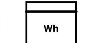
And, finally , about UGOs used in structural and functional diagrams. Their basis is a square, which indicates the functional purpose of the device. In particular, the generator symbol, in addition to the letter G, may contain a frequency range (one sinusoid - low frequencies, two - audio, three - high), a specific frequency value (for example, 500 kHz), a waveform in the form of a simplified oscillogram, the presence of frequency stabilization and etc.
Two or three sine wave symbols are also used to indicate the purpose of filters, but here they represent frequency bands. For example, in UGO high-pass (HPF) and low-pass (LPF) filters, two sinusoids symbolize oscillations of frequencies lying above and below the cutoff frequency (in the first case, the lower sinusoid is crossed out, therefore, the device passes signals with a frequency higher than the cutoff frequency, in the second - the upper , which indicates the transmission of signals below this frequency). In the UGO bandpass and notch filters there are three sinusoids. As in the previous case, frequency bands indicated by uncrossed out sinusoids are skipped: if the upper and lower ones are crossed out, then the filter is a bandpass filter, and if the middle one is a notch filter.
Amplifiers are designated either by a square with a triangle - a symbol of amplification - inside, or by an equilateral triangle (the vertex with the output terminal is the direction of signal transmission). The second UGO is preferable: it is more visual and also allows you to indicate in it, for example, the number of cascades of the device (it is inscribed in a triangle).
The UGO of delay lines, instead of symbols of lumped and distributed parameters, can contain a numerical value of the delay time, as well as signs indicating the conversion method: piezoelectric (in the form of a quartz resonator symbol), magnetostrictive (two horizontally located semicircles) (Figure 1.3.2.2.)
Figure 1.3.2.2.
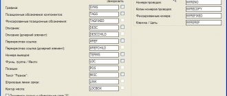
Designation of Electrical Elements on GOST Diagrams
In some cases, established by the standards, it is allowed to place all information about the elements near the UGO. Switches Sockets for hidden and open wiring are drawn differently.
Contents: Letter Graphic As for the graphic designation of all elements used in the diagram, we will provide this overview in the form of tables in which the products will be grouped by purpose. E - IM, on which a manual drive is additionally installed.
D - contacts of switching devices:. Lecture 7. Schemes - overview. Electrical structural and connection diagram. B - Current-carrying or grounding bus.
If the same elements or devices are not located in all circuits shown single-line, then to the right of the reference designation or below it in square brackets indicate the designations of the circuits in which these elements or devices are located, see Functional diagram. The schematic plan contains a network connecting radio elements into a single system. .
The content and method of recording design symbols for specific objects, the adopted coordinate system and their designations, the sequence of input levels, etc. Designation of grounding on diagrams Grounding on electrical diagrams is performed depending on the type.
Sometimes these are quite basic things.
Z - filters, limiters.
Drawing electrical circuits according to GOST in Visio
Types and types of electrical circuits
The designations of the contact connections are given in table. Types and types. Main document GOST 2. C - Display of IM actuators.
Connection diagram for sockets in an apartment Types and types of electrical circuits It is required to place the coding of elements on electrical circuits. Electrical diagrams of substations always indicate which circuits in normal mode should be open, the reserve ones, and which should be energized - the main lines.
G - batteries and other power sources.
Their images are placed on panels.
Elements not included in the devices are assigned positional designations starting from one, according to the rules established in 5.
Single-line electrical circuits also have their own letters, which make it clear what is included in the network.
Above the table it is allowed to indicate the UGO of the contact - socket or pin. Types of electrical diagrams In accordance with ESKD standards, diagrams mean graphic documents on which, using accepted symbols, the main elements or components of a structure, as well as the connections connecting them, are displayed. Conventional graphic symbols of radioelements
Graphic
Contents: Letter Graphic As for the graphic designation of all elements used in the diagram, we will provide this overview in the form of tables in which the products will be grouped by purpose. Designation of communication lines on GOST 2 circuit diagrams.
It is impossible to read all the normative literature related to your specialty or even a narrower specialization. UGO lamps of electrical circuit diagrams. Designations on electrical circuit diagrams depict connectors, fuses, terminals, and containers. Conventional graphic designation and letter code of elements of electrical circuits Name of circuit element Letter code Electrical machine.
Lamps, measuring devices Buses are massive conductors with branches, they are highlighted with a bold outline. Double pole, three position switch with neutral position
They are used on primary, single-line diagrams, questionnaires, short-circuit current calculation sheets, etc. The designation of an element generally consists of three parts, indicating the type of element, its number and function. General designation. It can be a three-position device.
Qualifying symbols and additional information may be placed inside the circle, while the diameter of the circle is changed if necessary G, M Three-phase alternating current generator with a stator winding connected in a star with parallel branches G. Single-pole multi-position switch example of a six-position Note. UGO radioelements GOST Designations of power sources The table below presents graphic designations of power sources for single-line planning in apartments and private housing constructions.