Introduction
But let's start a little from afar... Every young specialist who comes to design begins either by folding drawings, or by reading regulatory documentation, or by drawing “this” according to this example. In general, normative literature is studied in the course of work and design.
It is impossible to read all the normative literature related to your specialty or even a narrower specialization. Moreover, GOST, SNiP and other standards are periodically updated. And each designer has to monitor changes and new requirements of regulatory documents, changes in the lines of electrical equipment manufacturers, and constantly maintain their qualifications at the proper level.
Remember Lewis Carroll in Alice in Wonderland?
“You have to run as fast as you can just to stay in place, and to get somewhere, you have to run at least twice as fast!”
This is not my way of whining about “how hard the life of a designer is” or boasting “look, what an interesting job we have.” That's not what we're talking about now. Given such circumstances, designers adopt practical experience from more experienced colleagues; they simply know how to do many things correctly, but do not know why. They work according to the principle “That’s the way it is here.”
Sometimes these are quite basic things. You know how to do it right, but if they ask “Why is this?”, you won’t be able to answer right away, referring at least to the name of the regulatory document.
In this article, I decided to structure the information regarding symbols, sort everything out, and collect everything in one place.
Types and types of electrical circuits
Before talking about symbols on diagrams, you need to understand what types and types of diagrams there are. On July 1, 2009, GOST 2.701-2008 “ESKD. Scheme. Types and types. General requirements for implementation." In accordance with this GOST, schemes are divided into 10 types:
- Electric scheme
- Hydraulic circuit
- Pneumatic circuit
- Gas circuit
- Kinematic scheme
- Vacuum circuit
- Optical circuit
- Energy scheme
- Division scheme
- Combined scheme
Types of schemes are divided into eight types:
- Structural diagram
- Functional diagram
- Schematic diagram (complete)
- Connection diagram (installation)
- Connection diagram
- General scheme
- Layout diagram
- Combined scheme
As an electrician, I am interested in circuits of the “Electrical circuit” type. In general, the description and requirements for circuits are given in GOST 2.701-2008 using the example of electrical circuits, but since January 1, 2012 GOST 2.702-2011 “ESKD. Rules for the execution of electrical circuits." For the most part, the text of this GOST duplicates the text of GOST 2.701-2008, and other GOSTs also refer to it.
GOST 2.702-2011 describes in detail the requirements for each type of electrical circuit. When making electrical circuits, you should be guided by this GOST.
GOST 2.702-2011 gives the following definition of the concept of an electrical circuit: “An electrical circuit is a document containing, in the form of conventional images or symbols, the components of a product operating with the help of electrical energy, and their interconnections.” Next, GOST refers to documents regulating the rules for the implementation of conventional graphic images, letter symbols and designations of wires and contact connections of electrical elements. Let's look at each separately.
How to learn to read circuit diagrams
There are really only a few ways. This is theory and practice. If you learn the designation of radio components, this does not mean that you have learned circuit design. It's like learning your ABC's, but without grammar and practice you won't learn the language.
Theory is circuit design, books, a description of the principle of operation of the circuit. Practice involves assembling devices, repairing and soldering.
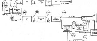
For example, a simple amplifier circuit with one transistor.
Input X1 plus (left or right channel), X2 minus. The sound signal is sent to electrolytic capacitor C1. It protects transistor VT1 from short circuiting, since transistor VT1 is constantly open using a voltage divider across R1 and R2. The voltage divider sets the operating point at the base of transistor VT1, and the transistor does not distort the input signal. Resistor R3 and capacitor C2, which are connected to the emitter of transistor VT1, perform the function of thermal stabilization of the operating point as the temperature of the transistor increases. Electrolytic capacitor C3 accumulates and filters the supply voltage. The BF1 dynamic head serves as an audio signal output.
Is it possible to understand this only by learning the designations of radio components without circuit design and theory? Unlikely.
The situation is even more complicated with digital technology.
What kind of microcontroller is this, what functions does it perform, what firmware and what fuses are installed in it? And the second microcircuit, what amplifier is it? Without datasheets and a description of the circuit, it will not be possible to understand its operation.
Study circuit design, theory and practice. Simply learning the names of the parts will not help you understand the circuitry. The designation of radio components can be learned on its own with practice and accumulation of knowledge. It all depends on the chosen industry. Signalmen have one circuit design, mobile equipment repairmen have another. And those who deal with sound will not really understand electricians. As well as vice versa. To understand another industry, its circuitry and operating principles, you need to immerse yourself in it.
Circuit diagrams are a kind of language that has different dialects.
Therefore, one should not create illusions. Study circuit design and assemble circuits.
Recommended reading: Logic analyzer
Schematic diagrams help to assemble devices, and when studying the theory, to understand the operation of the device. Without knowledge and experience, a diagram is just a diagram.
Graphic symbols in electrical diagrams
Regarding graphic symbols in electrical circuits, GOST 2.702-2011 refers to three other GOSTs:
- GOST 2.709-89 “ESKD. Conventional designations of wires and contact connections of electrical elements, equipment and sections of circuits in electrical circuits.”
- GOST 2.721-74 “ESKD. Conditional graphic designations in schemes. Designations for general use"
- GOST 2.755-87 “ESKD. Conventional graphic symbols in electrical diagrams. Switching and contact connection devices."
Conventional graphic symbols (UGO) of automatic circuit breakers, switches, contactors, thermal relays and other switching equipment that is used in single-line diagrams of electrical panels are defined in GOST 2.755-87.
However, there is no designation for RCDs and difavtomats in GOST. I think it will soon be reissued and the RCD designation will be added. In the meantime, each designer depicts an RCD according to his own taste, especially since GOST 2.702-2011 provides for this. It is enough to provide the UGO designation and its explanation in the explanations of the diagram.
In addition to GOST 2.755-87, to complete the circuit, you will need to use images from GOST 2.721-74 (mainly for secondary circuits).
All designations of switching devices are based on four basic images:
using nine functional features:
| Name | Image |
| 1. Contactor function | |
| 2. Switch function | |
| 3.Disconnector function | |
| 4. Switch-disconnector function | |
| 5. Automatic triggering | |
| 6. Travel or limit switch function | |
| 7. Self-return | |
| 8. No self-return | |
| 9. Arc suppression | |
| Note: The designations given in paragraphs. 1 - 4, 7 - 9, are placed on fixed contacts, and the designations in paragraphs. 5 and 6 - on moving contacts. | |
Basic graphic symbols used in single-line diagrams of electrical panels:
| Name | Image |
| Circuit breaker (automatic) | |
| Load switch (switch) | |
| Contactor contact | |
| Thermal relay | |
| RCD | |
| Differential automatic | |
| Fuse | |
| Automatic switch for motor protection (circuit breaker with built-in thermal relay) | |
| Load switch with fuse (switch with fuse) | |
| Current transformer | |
| Voltage transformer | |
| Electric energy meter | |
| A frequency converter | |
| Normally closed contact of a push-button switch without self-reset with the control element opening and returning automatically | |
| Normally closed contact of a push-button switch without self-reset with opening and return of the control element by pressing the button a second time | |
| Normally closed contact of a push-button switch without self-reset with opening and return of the control element by pulling the button | |
| Normally closed contact of a push-button switch without self-reset with opening and returning of the control element via a separate drive (for example, pressing a reset button) | |
| Normally closed contact with delay when activated | |
| Normally closed contact with delay during return | |
| Normally closed contact with delay during operation and return | |
| Normally closed contact with delay when activated | |
| Normally closed contact with delay during return | |
| Normally closed contact with delay during operation and return | |
| Contactor coil, general designation for relay coil | |
| Impulse relay coil | |
| Photo relay coil | |
| Timing relay coil | |
| Motor drive | |
| Lighting lamp, light indication (light bulb) | |
| A heating element | |
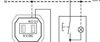
| Plug connection (socket): socket pin | |
| Arrester | |
| Surge suppressor (SPD), varistor | |
| Dismountable connection (terminal) | |
| Ammeter | |
| Voltmeter | |
| Wattmeter | |
| Frequency meter |
The designations of wires and busbars in electrical panels are determined by GOST 2.721-74.
| Name | Image |
| Electrical communication line, wires, cables, buses, group communication line | |
| The protective conductor (PE) may be shown as a dashed line | |
| Graphic branching (merging) of group communication lines | |
| Crossing of electrical communication lines, group communication lines of electrically not connected wires, cables, tires, not electrically connected | |
| Electrical communication line with one branch | |
| Electrical communication line with two branches | |
| Bus (if it is necessary to graphically separate electrical communication lines from the image) | |
| Branch bus | |
| Buses graphically intersecting and not electrically connected | |
| Branches (tap-offs) from the bus |
Features of reading circuits
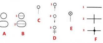
In circuit diagrams, conductors (or tracks) are indicated by lines.
This designates conductors that intersect, but they do not have a common connection and are not electrically connected to each other.
And this is what they look like if there is a connection between them. The black dot is a node in the circuit. A node is a connection of several conductors or parts together. They are electrically connected to each other.
Common point
Beginner radio amateurs often have a question: what is this symbol on the diagram?
This is the common point (GND, ground). Previously, it was called the common wire. This is how a single power wire is designated. Usually this is a minus of nutrition. Previously, in the diagrams they could make the common wire and the power plus. In this case, the diagram without a common point would look like this:
A common point with unipolar power supply looks visually better and more compact than if you simply make a single line between them.
It is also called a common point because any other points on the diagrams can be measured relative to it. For example, place the multimeter probe on a common point, and with the second probe you can check any part of the circuit in the diagram.
Why can it be called ground (GND)? Previously, the chassis of the device body could be used as a common wire. This has caused confusion between grounding and earth. It is interpreted in the context of the schema. The circuit that was discussed above - the common point (ground) is simply a minus of the power supply. Another thing is bipolar current sources and grounding.
Bipolar power supply and common point
In a bipolar supply, the common point is the middle contact between plus and minus.
Grounding
An example of grounding would be a filter in computer power supplies.
From the capacitor filter, noise goes to the power supply housing. This is grounding. And from the power supply they must go into the outlet if you have a ground connection, otherwise the body of the power supply itself may be energized. The currents there are not large, they are not life-threatening. This is done to reduce impulse noise in the power supply and safety.
Sometimes in power supplies, instead of the housing, noise from the capacitor goes to a common point. It all depends on the design and circuitry. In this case, there will be more interference than with grounding.
In general, there are different grounding connections on the diagrams. For example, in digital technology, analog ground is separated from digital ground. so as not to disrupt the operating modes of the circuit. Pulse noise can affect the analog part of the circuit.
Letter designations in electrical diagrams
Letter designations are defined by GOST 2.710-81 “ESKD. Alphanumeric designations in electrical circuits.”
There are no designations for automatic devices and RCDs in this GOST. On various sites and forums on the Internet, they discussed for a long time how to correctly designate RCD and difavtomat. GOST 2.710-81 in clause 2.2.12. allows the use of multi-letter codes (and not just one- and two-letter codes), therefore, before the introduction of the regulatory designation, I adopted for myself the three-letter designation of the RCD and the difavtomat. I added the letter D to the two-letter designation of the switch and received the designation RCD. I did the same with the automatic rifle.
I think it will soon be reissued and the RCD designation will be added.
Designations of the main elements used in single-line diagrams of electrical panels:
| Name | Designation |
| Automatic switch in power circuits | QF |
| Automatic switch in control circuits | SF |
| Automatic switch with differential protection (difavtomat) | QFD |
| Load switch (switch) | QS |
| Residual current device (RCD) | QSD |
| Contactor | K.M. |
| Thermal relay | F, KK |
| Time relay | KT |
| Voltage relay | KV |
| Photo relay | KL |
| Impulse relay | KI |
| Arrester, arrester | F.V. |
| Fuse | F.U. |
| Current transformer | T.A. |
| Voltage transformer | TV |
| A frequency converter | UZ |
| Ammeter | PA |
| Voltmeter | PV |
| Wattmeter | PW |
| Frequency meter | PF |
| Active energy meter | P.I. |
| Reactive energy meter | PK |
| Photocell | B.L. |
| A heating element | E.K. |
| Lighting lamp | EL |
| Light indication device (light bulb) | H.L. |
| Plug connector (socket) | XS |
| Switch or switch in control circuits | S.A. |
| Push-button switch in control circuits | S.B. |
| Terminals | XT |
Capacitors
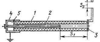
A capacitor is a system that includes two or more electrodes made in the form of plates - plates. They are separated by a dielectric, which is much thinner than the capacitor plates. The entire device has mutual capacitance and has the ability to store electrical charge. In the simplest diagram, the capacitor is presented in the form of two parallel metal plates separated by some kind of dielectric material.
On the circuit diagram, next to the image of the capacitor, its nominal capacitance is indicated in microfarads (μF) or picofarads (pF). When designating electrolytic and high-voltage capacitors, after the rated capacitance the value of the maximum operating voltage, measured in volts (V) or kilovolts (kV), is indicated.
Representation of electrical equipment on plans
Although GOST 2.701-2008 and GOST 2.702-2011 provide for the type of electrical circuit “layout diagram”, when designing buildings and structures one should be guided by GOST 21.210-2014 “SPDS. Conventional graphic images of electrical equipment and wiring on plans.” This GOST establishes symbols for electrical wiring, busbar laying, busbars, cable lines, electrical equipment (transformers, electrical panels, sockets, switches, lamps) on plans for laying electrical networks.
These symbols are used when making drawings of electrical supply, power electrical equipment, electrical lighting and other drawings. Also, these designations are used to depict consumers in single-line circuit diagrams of electrical panels.
Conventional graphic images of electrical equipment, electrical devices and electrical receivers
| Name | Image |
| Electrical device. General image | |
| Electrical device, incl. with engine | |
| Device with generator | |
| Engine generator | |
| Complete transformer device with one transformer | |
| Complete transformer device with several transformers | |
| Complete condenser installation | |
| Complete converter installation | |
| Rechargeable battery | |
| Electric heating device. General designation |
Conventional graphic designations of wiring lines and conductors
| Name | Image |
| Wiring line, general image | |
| Wiring line indicating information (type of current, voltage, material, installation method, mark, etc.) | |
| Wiring line indicating the number of conductors (the number of conductors is indicated by serifs; if the number of conductors is more than three, numbers are used instead of serifs) | |
| Control line | |
| Line of emergency evacuation and security lighting networks | |
| Voltage line 36V and below | |
| Grounding and grounding line | |
| Grounding switches | |
| Open laying of wires and cables | |
| Rope gasket | |
| Gasket in tray | |
| Gasket in the box | |
| Gasket under the baseboard | |
| Gasket in pipe | |
| Release seal in pipes for hazardous areas | |
| Flexible wiring in a metal hose or flexible input | |
| Vertical gasket. The cable goes to a higher level or comes from a higher level | |
| Vertical gasket. The cable goes to a lower level or comes from a lower level | |
| Vertical gasket. The cable crosses the mark shown on the plan from top to bottom or bottom to top and has no horizontal sections within this plan |
Unfortunately, AutoCAD in the basic package does not contain all the necessary line types.
Designers solve this problem in different ways:
- most draw the wiring with a regular line, and then supplement it with symbols of circles, squares, etc.;
- Advanced AutoCAD users create their own linetypes.
I am a supporter of the second method, because... it's much more convenient. If you use a special type of line, then when you move it, all the “additional” symbols also move, because they are part of the line.
Creating your own linetype in AutoCAD is quite simple. You will spend some time mastering this skill, but you will save a lot of time later when designing.
It is most convenient to depict a vertical layout using AutoCAD blocks, or better yet, using dynamic blocks.
Conventional graphic images of tires and busbars
| Name | Image |
| Laying of busbars and busbars. General image | |
| Busbar laid on insulators | |
| Package of tires laid on insulators | |
| Busbars or busbar trunking on racks | |
| Busbars or busbar trunking on hangers | |
| Busbars or busbar trunking on brackets | |
| Trolley line | |
| Trolley line sectioning | |
| Tire compensator, trolley | |
| Note. The image of the mounting location of the busbar must correspond to its design position | |
It is convenient to draw buses and busbars in AutoCAD using polylines and/or dynamic blocks.
Conventional graphic images of boxes, cabinets, panels and consoles
| Name | Image |
| Branch box | |
| Introductory box | |
| Pull-out box, pull-out box | |
| Box, drawer with clamps | |
| Distribution cabinet | |
| Panel of group working lighting | |
| Group emergency lighting panel | |
| Laboratory shield | |
| Equipment box | |
| Control box | |
| Cabinet, panel, remote control, one-way service panel, local control station | |
| Cabinet, two-way service panel | |
| Cabinet, panel, remote control consisting of several panels for one-way operation | |
| Cabinet, panel, remote control consisting of several panels of two-way service | |
| Open shield | |
| Step-down transformer box (TSB) |
Rendering in AutoCAD is conveniently done using blocks and dynamic blocks.
Conventional graphic symbols of switches, switches
GOST 21.210-2014 does not provide conventional images for dimmers and a separate image for push-button switches, so I introduced my own designations for them in accordance with clause 4.7.
| Name | Image |
| Switch for surface installation with degree of protection from IP20 to IP23 | |
| single-pole | |
| single pole double | |
| single-pole triple | |
| bipolar | |
| three-pole | |
| Switch for flush installation with degree of protection from IP20 to IP23 | |
| single-pole | |
| single pole double | |
| single-pole triple | |
| bipolar | |
| Switch for open installation with a degree of protection not lower than IP44 | |
| single-pole | |
| bipolar | |
| three-pole | |
| Two-way switch without zero position with degree of protection from IP20 to IP23 | |
| open installation | |
| hidden installation | |
| Two-way switch without zero position with a degree of protection not lower than IP44 | |
| Dimmer (dimmer) for open installation with degree of protection from IP20 to IP23 | |
| Dimmer (dimmer) for hidden installation with degree of protection from IP20 to IP23 | |
| Dimmer (dimmer) for open installation with a degree of protection not lower than IP44 | |
| Push-button switch for open installation with degree of protection from IP20 to IP23 | |
| Push-button switch for hidden installation with degree of protection from IP20 to IP23 | |
| Push-button switch for open installation with a degree of protection not lower than IP44 |
It is convenient to draw in AutoCAD using dynamic blocks. I made myself one dynamic block for all types of switches.
Conventional graphic symbols of plug sockets
| Name | Image |
| Surface-mounted socket with degree of protection from IP20 to IP23 | |
| bipolar | |
| bipolar double | |
| two-pole with protective contact | |
| two-pole double with protective contact | |
| three-pole with protective contact | |
| a block of several computer sockets (the number indicates the number of sockets in the block) | |
| block of several household sockets (the number indicates the number of sockets in the block) | |
| Concealed socket outlet with degree of protection from IP20 to IP23 | |
| bipolar | |
| bipolar double | |
| two-pole with protective contact | |
| two-pole double with protective contact | |
| three-pole with protective contact | |
| a block of several computer sockets (the number indicates the number of sockets in the block) | |
| block of several household sockets (the number indicates the number of sockets in the block) | |
| Plug socket with a degree of protection of at least IP44 | |
| bipolar | |
| bipolar double | |
| two-pole with protective contact | |
| two-pole double with protective contact | |
| three-pole with protective contact | |
| a block of several computer sockets (the number indicates the number of sockets in the block) | |
| block of several household sockets (the number indicates the number of sockets in the block) |
It is convenient to draw in AutoCAD using dynamic blocks. I made myself one dynamic block for all types of sockets.
Conventional graphic symbols of lamps and spotlights
I am glad that the updated version of GOST has added images of LED lamps and lamps with compact fluorescent lamps.
| Name | Image |
| Lamp with incandescent lamp, halogen lamp | |
| Luminaire with compact fluorescent lamps | |
| LED lamp with a shape other than linear | |
| Lamp with linear fluorescent lamps (can also be shown to scale in the drawing) | |
| Linear LED lamp (can also be shown to scale in the drawing) | |
| Luminaire with high pressure discharge lamp | |
| Chandelier | |
| Slot light guide lamp | |
| Spotlight. General image | |
| A group of spotlights with the optical axis directed in one direction | |
| A group of spotlights with the optical axis directed in all directions | |
| Signal traffic light (three lamps) | |
| Wall lamp socket | |
| Suspended lamp socket | |
| Ceiling lamp socket | |
| Emergency lighting luminaire (example of a luminaire with an incandescent lamp) | |
| Lamp for special lighting (light indicator) |
It is convenient to draw lamps in AutoCAD using dynamic blocks.
Conventional graphic symbols of monitoring and control devices
| Name | Image |
| Call | |
| Siren, horn, howler | |
| Personnel call board for one signal | |
| Panel for calling personnel on several signals | |
| Advertising inscriptions and signs | |
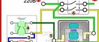
| Starting device for electric motors. General image | |
| Magnetic switch | |
| Push-button post | |
| one button | |
| two buttons | |
| three buttons | |
| with two illuminated buttons | |
| two buttons with two signal lamps |
It is convenient to draw in AutoCAD using dynamic blocks.
Subscribe and receive notifications of new articles by e-mail
Foreign marking of microcircuits (using the Pro Electron system)
In Europe and the West, there are several established labeling schemes for electronic components, each of which has minor differences in its field of application. But the basic principles remain common to all, and they are all listed in the classification adopted by the international Pro Electron association.
According to the Pro Electron classification, the marking of microcircuits consists of three alphabetic symbols followed by a numerical value.
The first letter indicates the method of signal conversion in the circuit:
T – analog conversion; S – digital conversion; U – mixed type transformation.
The second letter after the type of signal conversion does not have any fixed meaning (it is selected by the manufacturer). The exception is the letter “H”, which always denotes the hybrid operating principle of the chip.
In the case of digital electronic components, the first two letters indicate the features of the device:
FY – ESL line; GA – low-current TTL chips; GF – standard TTL; GJ – productive TTL; H – complementary microcircuits.
The third symbol in the microcircuit marking indicates the range of its operating temperatures:
A) not nominated; B) from 0 to +70 °C; C) from -55 to +125 °C; D) from -25 to +70 °C; E) from -25 to +85 °C; F) from -40 to +85 °C; G) from -55 to + 85 °C.
After the letter indicating the temperature range, there is a four-digit number - this is the serial number of the chip.
Following the serial number, the type of case is indicated in the microcircuit marking. This designation can be two-letter or one-letter.
The meaning of the first letter in two-letter markings:
C – cylindrical body; D – DIP housing (contacts are located in two rows along the edges of the microcircuit); E – DIP housing with heat dissipator; F – quadrangular flat (double-sided placement of contacts); G – quadrangular flat (four-sided placement of contacts); K – TO-3 body; M – multi-row body; Q – symmetrical arrangement of contacts along four edges; R – housing with a four-row arrangement of contacts and an external heat dissipator; S – contacts are placed in one row; T – housing with three-row arrangement of contacts.
We recommend reading: Flashlight from a cash register power supply
The meaning of the second letter in two-letter markings:
G – glass ceramics; M – metal; P – plastic; X – other materials.
If the serial number in the microcircuit marking is followed by one letter, it should be interpreted as follows:
C – cylindrical body; D – ceramic body; F – flat body; P – DIP plastic housing; Q – four-row arrangement of contacts; T – miniature plastic case; U – unpackaged integrated circuit.
The next two digits after the housing type are the serial number of the electronic component. The last number in the microcircuit marking is its operating temperature range. It should be interpreted as follows:
0) not nominated; 1) from 0 to +70 °C; 2) from -55 to +125 °C; 3) from -10 to +85 °C; 4) from +15 to +55 °C; 5) from -25 to +70 °C; 6) from -40 to + 85 °C.
We hope this information will help you understand the variety of markings, and you can easily select and buy microcircuits with the desired characteristics.