DC power supplies, the circuit of which includes a rectifier (AC/DC converter), are popular devices widely used in automated test systems designed to test electrical equipment, modules, and wiring diagrams. They are also used to power various electronic equipment, electric motors, charge batteries, and carry out electrochemical processes. They convert AC mains voltage into stabilized DC voltage. Many models provide the ability to adjust output parameters.
A separate type of power supply (PS) is made up of converters (DC/DC converters). They operate on DC power. Their scope of application includes automated process control systems, energy, transport, telecommunications and information technologies, security and fire systems.
The main technical characteristics of DC power supplies are:
- Nominal input voltage.
- Rated output voltage and its adjustment range.
- Maximum load current.
- Accuracy of output voltage stabilization.
- Efficiency
In addition to the basic characteristics, other operating parameters are also of great importance, which we will consider in more detail.
Noises and pulsations
This characteristic of DC power supplies determines the quality of the output signal, as well as the choice between switching and linear power supplies. Switching converters are essentially noise generators. Devices that use pulse-width modulation to control the switching of power switches create noise in a certain frequency band. The noise repetition rate depends on the switching frequency of the switching power supply, and the amplitude is highly dependent on the equipment topology. Ripple is a fluctuation in the output voltage that is associated with the charging and discharging of the device. It can be reduced by increasing the input or output capacitance.
For many tasks related to testing electrical equipment, it is advisable to use linear rather than pulsed power supplies. Despite the fact that they are characterized by low efficiency, size and weight, and the generation of a significant amount of heat, they can be used in applications where high power is not required (up to 200 W per channel). Linear devices generate high-frequency noise that can be easily filtered out. They also have a high response rate to load changes. If the task at hand does not impose increased requirements on the level of noise and pulsation, it is better to choose a pulse converter. It is characterized by high power, compactness, wide adjustment ranges, and flexibility of settings.
Regulations
Taking into account the large number of electrical elements, a number of normative documents have been developed for their alphanumeric (hereinafter referred to as BO) and conventional graphic designations (UGO) to eliminate discrepancies. Below is a table showing the main standards.
Table 1. Standards for graphic designation of individual elements in installation and circuit diagrams.
| GOST number | Short description |
| 2.710 81 | This document contains GOST requirements for BO of various types of electrical elements, including electrical appliances. |
| 2.747 68 | Requirements for the dimensions of displaying elements in graphical form. |
| 21.614 88 | Accepted codes for electrical and wiring plans. |
| 2.755 87 | Display of switching devices and contact connections on diagrams |
| 2.756 76 | Standards for sensing parts of electromechanical equipment. |
| 2.709 89 | This standard regulates the standards in accordance with which contact connections and wires are indicated on diagrams. |
| 21.404 85 | Schematic symbols for equipment used in automation systems |
It should be taken into account that the element base changes over time, and accordingly changes are made to regulatory documents, although this process is more inert. Let's give a simple example: RCDs and automatic circuit breakers have been widely used in Russia for more than a decade, but there is still no single standard according to GOST 2.755-87 for these devices, unlike circuit breakers. It is quite possible that this issue will be resolved in the near future. To keep abreast of such innovations, professionals monitor changes in regulatory documents; amateurs do not have to do this; it is enough to know the decoding of the main symbols.
Output voltage change rate
This is an important parameter that is of great importance in the field of testing electrical appliances. During testing, different voltages are applied to the equipment to verify that it is functioning correctly within its operating range. The faster the power supply responds to changes in settings, the higher the testing performance. In standard devices, the time to set the output voltage with an accuracy of 1% is on average 50-500 ms. There are special circuits for regulated DC power supplies that can reduce this figure to 1-4 ms.
Graphic symbols
Each type of graphic document has its own designations, regulated by relevant regulatory documents. Let us give as an example the basic graphic symbols for different types of electrical circuits.
Examples of UGO in functional diagrams
Below is a picture depicting the main components of automation systems.
Examples of symbols for electrical appliances and automation equipment in accordance with GOST 21.404-85
Description of symbols:
- A – Basic (1) and acceptable (2) images of devices that are installed outside the electrical panel or junction box.
- B - The same as point A, except that the elements are located on the remote control or electrical panel.
- C – Display of actuators (AM).
- D – Influence of MI on the regulating body (hereinafter referred to as RO) when the power is turned off:
- RO opening occurs
- Closing RO
- The position of the RO remains unchanged.
- E - IM, on which a manual drive is additionally installed. This symbol may be used for any RO provisions specified in paragraph D.
- F- Accepted mappings of communication lines:
- General.
- There is no connection at the intersection.
- The presence of a connection at the intersection.
UGO in single-line and complete electrical circuits
There are several groups of symbols for these schemes; we present the most common of them. To obtain complete information, you must refer to the regulatory documents; the numbers of state standards will be given for each group.
Power supplies.
To designate them, the symbols shown in the figure below are used.
UGO power supplies on schematic diagrams (GOST 2.742-68 and GOST 2.750.68)
Description of symbols:
- A is a constant voltage source, its polarity is indicated by the symbols “+” and “-”.
- B – electricity icon indicating alternating voltage.
- C is a symbol of alternating and direct voltage, used in cases where the device can be powered from any of these sources.
- D – Display of battery or galvanic power supply.
- E- Symbol of a battery consisting of several batteries.
Communication lines
The basic elements of electrical connectors are presented below.
Designation of communication lines on circuit diagrams (GOST 2.721-74 and GOST 2.751.73)
Description of symbols:
- A – General display adopted for various types of electrical connections.
- B – Current-carrying or grounding bus.
- C – Designation of shielding, can be electrostatic (marked with the symbol “E”) or electromagnetic (“M”).
- D - Grounding symbol.
- E – Electrical connection with the device body.
- F - On complex diagrams, consisting of several components, a broken connection is thus indicated; in such cases, “X” is information about where the line will be continued (as a rule, the element number is indicated).
- G – Intersection with no connection.
- H – Joint at intersection.
- I – Branches.
Designations of electromechanical devices and contact connections
Examples of the designation of magnetic starters, relays, as well as contacts of communication devices can be seen below.
UGO adopted for electromechanical devices and contactors (GOSTs 2.756-76, 2.755-74, 2.755-87)
Description of symbols:
- A – symbol of the coil of an electromechanical device (relay, magnetic starter, etc.).
- B – UGO of the receiving part of the electrothermal protection.
- C – display of the coil of a device with mechanical interlock.
- D – contacts of switching devices:
- Closing.
- Disconnecting.
- Switching.
- E – Symbol for designating manual switches (buttons).
- F – Group switch (switch).
UGO of electric machines
Let us give several examples of displaying electrical machines (hereinafter referred to as EM) in accordance with the current standard.
Designation of electric motors and generators on circuit diagrams (GOST 2.722-68)
Description of symbols:
- A – three-phase EM:
- Asynchronous (squirrel-cage rotor).
- The same as point 1, only in a two-speed version.
- Asynchronous electric motors with phase-phase rotor design.
- Synchronous motors and generators.
- B – Collector, DC powered:
- EM with permanent magnet excitation.
- EM with excitation coil.
Designation of electric motors on diagrams
UGO transformers and chokes
Examples of graphic symbols for these devices can be found in the figure below.
Correct designations of transformers, inductors and chokes (GOST 2.723-78)
Description of symbols:
- A – This graphic symbol can indicate inductors or windings of transformers.
- B – Choke, which has a ferrimagnetic core (magnetic core).
- C – Display of a two-coil transformer.
- D – Device with three coils.
- E - Autotransformer symbol.
- F – Graphic display of CT (current transformer).
Designation of measuring instruments and radio components
A brief overview of the UGO of these electronic components is shown below. For those who want to become more familiar with this information, we recommend viewing GOSTs 2.729 68 and 2.730 73.
Examples of graphic symbols for electronic components and measuring instruments
Description of symbols:
- Electricity meter.
- Picture of an ammeter.
- Device for measuring network voltage.
- Thermal sensor.
- Fixed value resistor.
- Variable resistor.
- Capacitor (general designation).
- Electrolytic capacity.
- Diode designation.
- Light-emitting diode.
- Image of a diode optocoupler.
- UGO transistor (in this case npn).
- Fuse designation.
UGO lighting devices
Let's look at how electric lamps are displayed on a circuit diagram.
An example of how light bulbs are indicated on diagrams (GOST 2.732-68)
Description of symbols:
- A – General image of incandescent lamps (LN).
- B - LN as a signaling device.
- C – Typical designation of gas-discharge lamps.
- D – High-pressure gas-discharge light source (the figure shows an example of a design with two electrodes)
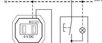
Designation of elements in the electrical wiring diagram
Concluding the topic of graphic symbols, we give examples of displaying sockets and switches.
An example of an image on the wiring diagrams of flush-mounted sockets
How sockets of other types are depicted is easy to find in the regulatory documents that are available on the Internet.
Designation of flush-mounted switches
Designation of sockets and switches
Response time to load changes
This parameter determines how quickly the power supply reacts to load changes or power surges. If the output current changes rapidly over a wide range of values, the output voltage also begins to decrease or increase at a high rate. The time it takes for a device to stabilize its characteristics is called reaction time to a change in load. Due to the use of feedback in the topology to control the output voltage, switching power supplies are characterized by a relatively slow response.
To protect the devices under test from severe overloads, it is recommended to use a preload. It is connected in parallel with the device under test and limits voltage surges. Modern switching power supplies have a response time of 40-80 µs, and linear ones - up to 1 µs.
Current sources on field-effect and bipolar transistors.
Circuits of current generators, types of current mirrors, Online calculator for calculating elements of current sources.At today’s event dedicated to the opening of the “Cultural and Leisure Center of the Lokhov Municipality”, we will talk about the types of sources of constant and, preferably, stable output current. - If voltage can be understood with the mind, then current can only be understood with feeling! — the head of the artistic needlework circle, Semyon Samsonovich Eldykin, began his report. - The purpose of our amateur radio session today is to master the ordered movement of free electrically charged particles - as a sum of knowledge, physical skills and innate skills. “How to ground an ungrounded ground? How much vodka do you need to drink in grams to reduce body resistance by 1 kOhm? And how not to enter into intimate relationships with electricity? - will be the topic of our scientific colloquium.
Thanks to Semyon Samsonovich for the introductory words, but it’s time for us to move closer to the topic indicated in the title. Let us indulge in encyclopedic profundity:
“ A current source is an element, a two-terminal network, the current strength through which does not depend on the voltage at its terminals (poles). The terms current generator and ideal current source are also used…” Wikipedia teaches us.
Let's add to the editorial staff. The current source must have a large internal differential resistance , such that when the load resistance changes, the current strength in the load practically does not change. This opportunity is provided to us by a bipolar transistor on the collector side, a field switch on the drain side, or an operational amplifier between the inverting input and output.
There are several basic characteristics that characterize a current source . The first and main one is the output current. Secondly, its output impedance, which determines how much the source current varies depending on the load impedance. The third specification is the minimum and maximum voltage at the source output at which the node operates properly, i.e. the output transistor is in active mode. Fourth, temperature stability and the ability to withstand power supply voltage fluctuations.
To warm up, let's look at the circuits of the simplest current generators (sources) using transistors and operational amplifiers.
Fig.1
The bipolar transistor current source circuit is the worst. It has a full bouquet of shortcomings - temperature instability, the dependence of the current on fluctuations in the voltage of the power source, and the presence of the notorious Earley effect (the effect of the influence of the voltage between the collector and the base on the collector current). Here, the input divider on resistors R1, R2 sets the base current of the transistor Ib, the output current, to a first approximation, can be considered equal to In = Ik≈β×Ib.
The field-effect transistor circuit is not so sensitive to the instability of the power source, but it has another significant drawback - the practical impossibility of calculating the generator output current in advance due to the significant scatter in the parameters of these types of semiconductors. The maximum current of this type of source is equal to the initial drain current at R1=0 (datasheet characteristic), the minimum is limited by the voltage drop across the current-setting resistor R1.
Current generators based on operational amplifiers (inverting on the left, non-inverting on the right) are quite efficient devices that are close analogues of ideal current sources, and are practically free of the disadvantages inherent in transistor circuits. The only significant “but” in some cases is that the load is “floating”, i.e. not connected on any side to the ground. The current through the load is described with almost 100% accuracy by the formula In = Uin/R1.
Have you warmed up? The time has come to get rid of the shortcomings of the simplest current sources that we coughed up above.
Fig.2
The current stabilizer circuits presented in Fig. 2 will be useful in devices working with end consumers that are sensitive not so much to voltage stability as to the constancy of the current flowing through them. You don’t have to look far for examples - power supplies for LEDs, gas-discharge lamps, battery chargers, etc. All of them require a constant current or a current varying according to a certain algorithm at the output. The operating principle of the above schemes is extremely simple. As the load current increases, the voltage drop across the current-setting resistor R1 also increases proportionally. When this voltage drop reaches a level of ≈0.6V, transistor T1 begins to open, reducing the value of Ube (or Uzi) of the second transistor T2. It begins to close, and accordingly, the amount of current flowing through the load decreases. For a circuit based on a bipolar transistor, the value of the resistor Rb should be chosen based on considerations Rb For a field operator, due to its high input resistance, the value of the resistor Rз1 can be chosen quite high (tens of kilo-ohms). The only thing you need to keep a close eye on is the maximum permissible value of the gate-source voltage of the transistor. If it is less than Ep, you should add an additional resistor Rз2 of such a value that the formed divider brings the voltage at the gate within acceptable limits. The output current is calculated using the simple formula Iн≈0.6/R1. There is no temperature compensation in these circuits; the change in output current is ≈ 0.3% per °C.
| To reduce the dependence of the output current on supply voltage fluctuations, current sources (Fig. 4), called double current mirrors, have been widely used. The mechanism works as follows: Suppose the supply voltage has increased. Then the voltage drop across resistor R1 also increases. This leads to a decrease in the base potential of transistor VT3, transistor VT3 will close, its current Ie3 will decrease, and the base current Ib2 and In will also decrease and return to its original state. Ik1≈(Ep-1.4)/(R1+ Re1), In≈ Re1×(Ep-0.7)/(R1× Re2+ Re1× Re2). | |
| Fig.5 | The current source shown in Fig. 5, is called the Wilson current mirror circuit and provides a high degree of output current constancy by suppressing the manifestations of the Early effect (the effect of the voltage between the collector and the base on the collector current). Transistors T1 and T2 in this circuit are connected in the same way as in a conventional current mirror, but thanks to transistor T3, the collector potential of the current-setting T2 is fixed and does not affect the output current. All formulas are similar to the previous description: Ik1≈(Ep-1.4)/(R1+ Re1), In≈ Re1×(Ep-0.7)/(R1× Re2+ Re1× Re2). |
| Fig.6 | The cascode current generator shown in Fig. 6 has the advantages of a very high internal resistance and a significant reduction in the Early effect. The dynamic internal resistance of such a current reflector exceeds several MOhms. And again - everything is the same: Ik1≈(Ep-1.4)/(R1+ Re1), In≈ Re1×(Ep-0.7)/(R1× Re2+ Re1× Re2). It is easy to notice that for all types of reduced current mirrors, the formula for calculating the output current is the same. The formula is approximate and does not take into account the influence on the calculated indicators of insignificant values of the base currents of transistors, but makes it possible to calculate the values of current-setting elements with an error not exceeding 5-7%. |
If it is necessary to generate reverse current, you should turn the circuit upside down and replace the NPN transistors with reverse conduction semiconductors.
And according to tradition, I will provide a table that allows you to not bother too much, if you want to translate the described nodes into real life.
CALCULATION OF CURRENT SETTING ELEMENTS OF CURRENT SOURCES ON BIPOLAR TRANSISTORS.
Current sources based on field-effect transistors, due to the significant spread of parameters of this type of semiconductor, have found practical application mainly in the production of analog integrated circuits. At the same time, when using MOS structures of field-effect transistors, the circuitry of current mirrors is practically no different from the above current sources on bipolar counterparts.
Fig.6
Designing current sources using discrete field-effect transistors is, in my opinion, a rather impractical task. Another thing is specially designed semiconductors called current-stabilizing diodes (CRDs), which are based on an n-channel field-effect transistor. Fig.7
Field diodes have only two terminals and are optimized in terms of current-voltage characteristics. In their manufacture, it is possible to achieve a zero temperature coefficient by combining the CRD with a resistor that has the same but opposite temperature coefficient. Current-stabilizing diodes are not very well known among the broad masses of the amateur radio community, but in the meantime they are actively produced by bourgeois industrialists, they have a decent range of currents and a fairly wide range of operating voltages.
And on the next page we will continue the topic - we will devote it to current sources on operational amplifiers, as well as voltage-to-current converters on op-amps and transistors .
Possibility of parallel and serial connection of IP
Parallel connection of power supplies increases the output current. Many power supplies are equipped with a specialized parallel control bus. It allows you to create a single configuration from multiple sources. The system automatically determines which devices are master and which are slave.
Series connection of power supplies is used if increased voltage is required. However, it should not exceed the electrical insulation strength of the output terminals.
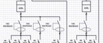
Types of electrical circuits
In accordance with ESKD standards, diagrams mean graphic documents on which, using accepted notations, the main elements or components of a structure, as well as the connections connecting them, are displayed. According to the accepted classification, there are ten types of circuits, of which three are most often used in electrical engineering:
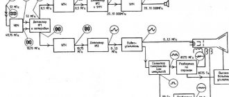
- Functional, it shows the node elements (depicted as rectangles), as well as the communication lines connecting them. A characteristic feature of this scheme is minimal detail. To describe the main functions of nodes, the rectangles displaying them are signed with standard letter designations. These can be various parts of the product that differ in functionality, for example, an automatic dimmer with a photo relay as a sensor or a regular TV. An example of such a scheme is presented below.
Example of a functional diagram of a television receiver - Fundamental. This type of graphic document displays in detail both the elements used in the design and their connections and contacts. The electrical parameters of some elements can be displayed directly in the document, or presented separately in the form of a table.
Example of a circuit diagram of a milling machine
If the diagram shows only the power part of the installation, then it is called single-line; if all elements are shown, then it is called complete.
Single Line Diagram Example
- Electrical wiring diagrams. These documents use positional designations of elements, that is, their location on the board, method and order of installation are indicated.
Installation diagram of a stationary flammable gas detector
If the drawing shows the wiring of the apartment, then the locations of lighting fixtures, sockets and other equipment are indicated on the plan. Sometimes you can hear such a document called a power supply diagram; this is incorrect, since the latter shows how consumers are connected to a substation or other power source.
Having dealt with the electrical circuits, we can move on to the designations of the elements indicated on them.
Digital programming
Many power supplies support digital programmability for constant voltage (CV) or constant current (CC) modes. The devices operate in voltage stabilization mode provided that the load current is less than the set value. After the electric current reaches a threshold value, the IP switches to current stabilization mode. The output voltage can be limited to prevent power overload. Configuration is carried out through the device control panel or from a computer via USB, LAN, GPIB interfaces.
Programming provides advanced control capabilities. For example, you can sequence changes in voltage and current, generate sawtooth and other signals for testing fuses and various electrical appliances.
Unstabilized power supplies
An unregulated power supply is the simplest type, consisting of a transformer, rectifier and low-pass filter. These power supplies typically have large voltage ripple (i.e., rapidly changing instability) and other AC voltage "noise" superimposed on the DC supply voltage output. If the input voltage changes, the output voltage will change proportionally. The advantage of an unregulated power supply is that it is cheap, simple and efficient.
Depending on the main purpose, electrical circuits are divided into the following types:
Combined electrical circuit (E0)
This type of diagram shows various types that are combined with each other in one drawing.
An example of a combined electrical circuit:
Electrical connection diagram (E5)
The connection diagram must show the product, its input and output elements (connectors, clamps, etc.) and the ends of wires and cables (stranded wires, electrical cords) connected to them for external installation, near which data on connecting the product (characteristics) should be placed external circuits and (or) addresses). The placement of images of input and output elements inside the graphic designation of the product should approximately correspond to their actual placement in the product. The diagram should indicate the positional designations of the input and output elements assigned to them on the circuit diagram of the product.
Example of electrical connection diagram:
Electrical connection diagram (installation) (E4)
The connection diagram should show all devices and elements included in the product, their input and output elements (connectors, boards, clamps, etc.), as well as connections between these devices and elements. The location of graphic symbols of devices and elements on the diagram should approximately correspond to the actual placement of elements and devices in the product. The arrangement of images of input and output elements or terminals within graphic symbols and devices or elements should approximately correspond to their actual placement in the device or element.
Example of electrical connection diagram:
Electrical circuit diagram (complete) (E3)
The circuit diagram shows all the electrical elements or devices necessary for the implementation and control of established electrical processes in the product, all the electrical connections between them, as well as the electrical elements (connectors, clamps, etc.) that terminate the input and output circuits. The diagram may depict connecting and mounting elements installed in the product for structural reasons. The circuits are performed for products in the off position.
An example of an electrical circuit diagram:
Electrical functional diagram (E2)
A functional diagram depicts the functional parts of a product (elements, devices and functional groups) participating in the process illustrated by the diagram, and the connections between these parts. The graphical construction of the diagram should give the most visual representation of the sequence of processes illustrated by the diagram.
An example of an electrical functional diagram:
Electrical structural diagram (E1)
The block diagram shows all the main functional parts of the product (elements, devices and functional groups) and the main relationships between them. The graphical construction of the diagram should provide the best idea of the sequence of interaction of functional parts in the product. On the interconnection lines, it is recommended to use arrows to indicate the direction of the processes occurring in the product.
An example of an electrical structural diagram:
Types of electrical circuits
In electrical engineering, according to the type of connection of electrical circuit elements, there are the following electrical circuits:
- serial electrical circuit;
- parallel electrical circuit;
- series-parallel electrical circuit.
Serial electrical circuit.
In a serial electrical circuit (Figure 2), all elements of the circuit are in series with each other, that is, the end of the first with the beginning of the second, the end of the second with the beginning of the first, etc.
Figure 2. Serial electrical circuit.
With such a connection of circuit elements, the current has only one flow path from the current source to the load. In this case, the total circuit current Itot will be equal to the current through each circuit element:
Itotal=I1=I2=I3
The voltage drop along the entire circuit, that is, in section A-B (Ua-b), will be equal to the voltage E applied to this section and equal to the sum of the voltage drops in all sections of the circuit (resistors):
E=Ua-b=U1+U2+U3
Parallel electrical circuit.
In a parallel electrical circuit (Figure 3.), all elements are connected in such a way that their beginnings are connected to one common point, and their ends to another.
Figure 3. Parallel electrical circuit.
In this case, the current has several flow paths from the source to the loads, and the total circuit current Itot will be equal to the sum of the currents of the parallel branches:
Itotal=I1+I2+I3
The voltage drop across all resistors will be equal to the applied voltage to the section with parallel connection of resistors:
E=U1=U2=U3
Series-parallel electrical circuit.
A series-parallel electrical circuit is a combination of a series and parallel circuit, that is, its elements are connected both in series and in parallel (Figure 4).
Figure 4. Series-parallel electrical circuit.
Functions of various parts of the circuit
Each element of the electrical circuit performs its own specific functions.
The current source supplies energy to current receivers - consumers.
Connecting wires deliver energy from the source to the consumers.
All kinds of buttons, switches, switches are used at the right times to connect consumers to the current source, as well as to disconnect them from the source.
Each element of the electrical circuit performs specific functions
In order for current to circulate through an electrical circuit, the circuit must be closed.
Therefore, any closed circuit consists of elements capable of conducting electric current - conductors.
If you open (break) the circuit in any part of it, then the electric current will stop flowing through it. They break the circuit at the right times using all kinds of switches.
If the circuit is opened, the current will stop
Power supplies with linear stabilizers
A linear regulator power supply is simply an unregulated power supply followed by a transistor circuit operating in its "active" or "linear" mode, hence the name linear regulator. A typical linear regulator is designed to output a fixed voltage for a wide range of input voltages, and simply drops any excess voltage across it to provide maximum output voltage to the load. This excess voltage drop results in significant power dissipation in the form of heat. If the input voltage becomes too low, the circuit will become unregulated, meaning it will not be able to maintain a constant voltage. It can only discard excess voltage, but cannot compensate for the lack of voltage in the unstabilized source section. Therefore, it is necessary to maintain the input voltage above the required output voltage by at least 1-3 volts, depending on the type of stabilizer. This means that power equivalent to at least 1-3 volts times the full load current will be dissipated by the regulator circuit, generating a lot of heat. This makes power supplies with linear regulators quite inefficient. Plus, to get rid of all that heat, they have to use large radiators, which makes them big, heavy, and expensive.
UPS transformer and its application
One of the options for using this uninterruptible power supply element is the manufacture of a power supply. Remove the transformer, use an ohmmeter to find the winding with the highest resistance: 220 V is supplied to it. Now measure the voltage at the remaining terminals and find 15 V. All that remains is to connect a rectifier bridge and a smoothing capacitor to it - the block is ready. The simplest diagram for connecting a transformer from an uninterruptible power supply:
Such a homemade device can be used, for example, to recharge a laptop.
How to draw up a diagram correctly
A wiring diagram for beginners should be drawn on a checkered sheet of paper to ensure that all the lines and symbols are drawn evenly. Most often, the common wire is connected to the negative pole of the DC source. Linear elements are drawn from left to right. It is not recommended to draw more than 3 parallel conductors in a row, this will make the diagram difficult to read.
To compile PS, MS and drawings, you can use computer applications. One of them, Microsoft Visio, is part of the office suite. This program's feature set includes over 100 symbols for parts, conductors, and mechanisms. Automatic snapping of the ends of drawn elements is supported, which ensures the integrity of the diagram when editing.
Another application for correctly drawing up diagrams is the domestic sPlan. The program is distributed free of charge and has a Russified interface and help. Using sPlan, electrical circuits are created that comply with GOST. In addition, there is a built-in graphic editor that allows you to create an installation diagram.