Visual diagnostics
Radio components do not simply fail. And the consequences of their malfunctions can be seen visually. Let's look at the most common faults when they can be noticed visually.
Conventionally, all causes of malfunctions can be divided into 3 categories: moisture ingress, mechanical and electrical damage.
All of them can be interconnected, and even depend on each other. Let's take a closer look at each typical microcircuit malfunction with diagnostics and examples.
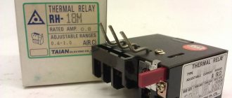
Checking high-voltage ignition wires
To ensure that the ignition system is 100% operational, you need to know how to check the high-voltage wires on a car. This can be done visually, using a piece of wire or using a multimeter. Each of the methods is worth considering in more detail.
Visual inspection. It must be carried out in a room with dim lighting. To do this, open the hood of the car and start the engine. Carefully inspect the wires in the dark: if a spark jumps along them or at the connections with the coil, distributor (module), spark plugs, then the explosive must be replaced. Using a piece of wire. Strip both ends of the insulation. Securely attach one of them to the ground of the machine. Next, darken the garage and start the engine.
Carefully run the other end of the wire along each high-voltage wire. The presence of a spark indicates the need to purchase new explosives.
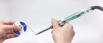
Using a Multimeter
This is the most complex, but also accurate method for checking the performance of high-voltage wires, so it must be considered separately. To work correctly with the tester, you first need to prepare it:
- switch the device to resistance measurement mode (ohmmeter);
- pull out one of the explosives, disconnecting it from the ignition module (distributor) and the cylinder spark plug;
- connect the multimeter probes to the ends of the wire and evaluate the tester readings.
Technical parameters, including resistance, must be indicated on the insulation of the high-voltage wire. If it is fully operational, the value will be in the range of 3.5-10 kOhm (the parameter depends on the manufacturer). If the readings are greater or less than these limits, then the wire must be replaced.
It is worth noting that the resistance of each cable will be different, which is due to its length. It is recommended to install armored ignition wires as a set. Below are the BB data of the most famous companies:
- Cargen: resistance about 9 kOhm.
- Tesla: 6 kOhm.
- Slon: 4 kOhm for the wire of the first cylinder, gradually increasing to 7 kOhm for the last.
Electrical damage
The microcircuit may fail due to a simple short circuit. Typically, holes may appear on such microcircuits. This is called thermal runaway.
Thermal breakdown is when a current passes through the microcircuit, which damages it so much that a hole appears on the housing. Those. it “burnt” and even smoked for a while. The hole in the case appears from a large amount of heat, which created a current passing through the microcircuit. The microcircuit is not designed for such a current, so its body cannot withstand it and begins to break down in a vulnerable area.
Below is a clear example of thermal breakdown of a stepper motor control chip (driver).
A heatsink was installed on the chip, but even this did not save the chip from thermal breakdown.
As a rule, such microcircuits completely lose their functionality. And with such a thermal breakdown, the tracks can be damaged. After soldering the damaged microcircuit, carefully look at the tracks and surrounding parts so that they are intact and without damage. The PCB may also swell, but this happens very rarely.
Also, if there is a short circuit, the microcircuits can become completely charred and leave traces of soot on the board and surrounding parts. Carbon deposits must be removed from the board because... it can conduct current.
Checking microcircuits with a multimeter
Another example of an absolutely similar malfunction can be found in laptops.
For example, on laptop boards, it is enough to accidentally short-circuit the USB port (or by static electricity), and the hub (group of chips) may immediately fail. And this is a 100% short circuit. And at the same time, the microcircuit will be visually without any damage. However, such microcircuits can be easily checked for serviceability with a multimeter.
As an example, let's look at checking a microcircuit in a DIP package.
Each chip has power. And as a rule, it is this that fails if the microcircuit does not perform its functions.
Below is an example of the pinout of the NE555 timer chip.
This microcircuit (like any other) has power. Power is designated Vcc (roughly speaking plus) and GND (minus). Using a multimeter, you can check the integrity of the power supply, as if we were checking a regular diode for serviceability.
In the example below, a different microcircuit will be tested with a multimeter, but the essence is the same.
Switch the multimeter to dialing mode.
The continuity mode is usually shown as a UGO diode with a sound emission sign.
And now it’s enough to ring Vcc and GND (power supply) of the microcircuit.
Like a diode, it should not show zeros during a direct test (the positive probe of the multimeter to the plus (Vcc) of the microcircuit, the negative probe of the multimeter to the minus (GDD)).
Same with the reverse.
Of course, this method is not universal. For example, there are boards in which the wiring near the microcircuits can affect the measurements. Either you will have to unsolder the microcircuit from the board, or unsolder the parts or pins of the microcircuit so that they do not affect the test.
However, diagnosing the same laptops for the health of the video chip or hub is quite simple if you know their operating resistances and conditions. And there the influence of the components is not only great. It all depends on the fee.
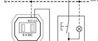
Checking using service manuals
Each manufactured equipment has service manuals. Using them, you can check the performance of boards (and, accordingly, microcircuits) by following the instructions. For example, “Is there a voltage of 5V at pin number 12?” And then the next few steps that will lead to the final repair decision.
Although the service manuals recommend replacing the entire board at once, even without specific replacement of radio components.
Of course, it will not be possible to find a manual for any equipment due to various circumstances, but you can find equipment that uses a similar chip or board. Smartphones from different manufacturers may have the same power controllers. Therefore, experience and information search skills are important here.
Also, feel free to ask for information about chips on electronics forums and social media groups. (of course, before doing this, I independently searched for information in all available sources)
Typical connection diagrams
In addition to service manuals, there are also datasheets with simple shutdown diagrams. Those. Roughly speaking, you can assemble a circuit to simply test the functionality of the microcircuits.
Why does the microcircuit heat up and methods for diagnosing it
Another typical case of a short circuit is when the microcircuit gets very hot. Several options are possible here.
Most novice repairmen immediately declare that if the microcircuit heats up, then it is the one that is faulty. This is partly true, but only in rare cases. If the microcircuit heats up, this does not mean that it is faulty. But this is precisely what affects its functions and the overall performance of the board and the device as a whole.
As an example, consider the situation with power controllers on smartphones. These microcircuits control the power supply to the entire device. And it is through it that all currents pass. Let's say the microcircuit gets hot and you change it. And again the same problem. But the problem turned out to be not in it at all, but in another part of the board, where there is a short circuit.
A large current passes through the microcircuit precisely to that part of the board where the faulty radio component is located, which causes the microcircuit to heat up greatly.
You can either visually find a faulty shorting part (it may be damaged, with traces of oxide, darker, with traces of rust, etc.), or by the heat generated.
If problems may arise with visual detection (without a microscope, finding a damaged SMD capacitor or resistor on a board is quite problematic + attention is needed), then with detection by the heat generated, everything can be much simpler.
Of course, there are different cases here too. Heating from 2 A is one thing, and heating from 20 mA is another thing. Although the nature of the faults may be identical, different diagnostic methods will have to be used.
Diagnostics using a cash receipt
Connect the board to a laboratory power supply with short circuit current limitation. This is necessary in order not to completely finish off the heating chip. Next, we lean the cash receipt against the board.
And as a result, you can see on paper the silhouette of the part that is causing the short circuit.
Naturally, there will be a trace from the heating of the microcircuit, but the microcircuit itself is heated by another faulty part.
You can also use a freezer to freeze the board to quickly determine the point on the board where the short circuit is located. There can be four possible outcomes:
- The heating of the microcircuit occurs due to a short circuit in another part of the board. In this case, it is not the microcircuit itself that is faulty, but another radio component. The microcircuit simply stands in the way of a large current and passes it through itself;
- Both the microcircuit and other radio components are faulty. It so happened that a faulty radio component finished off the microcircuit. It cannot constantly heat up, and sooner or later it will fail;
- Still, the microcircuit itself is faulty. Yes, it happens. especially if there is a problem with contacts;
- There are traces of moisture on the board. . Next we will analyze such cases.
How to measure voltage across a capacitor
In addition, to determine whether the element is working, it is necessary to check whether its real voltage corresponds to the nominal one. To do this, you should use the tester in voltmeter mode, and you also need to have a power source to charge the devices. The voltage value should be less than that for which the drives are designed. To measure, you will need to connect the probe to the terminal and wait a little until it is fully charged. When switching the device to voltmeter mode, it is necessary to check the voltage output by the storage device. The value that appears on the device display at the initial stage of measurement must correspond to the declared indicators.
It should be taken into account that during the testing process the drive loses charge and, obviously, the voltage will quickly decrease, which is why the initial measurement value is important.
There is a more affordable way to test capacitors, but it is only suitable for products with much higher capacitance. After the drive is fully charged, you need to take a simple screwdriver with an insulated handle, bring its metal part to the terminals and close them. If, after the manipulations performed, a spark occurs, this indicates the operability of the element. If it was absent or weak, then this indicates the inability of the device to hold a charge.
Mechanical damage
Mechanical damage to microcircuits (and radio components in particular) is extensive. This may be the consequences of impacts on the device body, and careless operation and repair.
Hull damage
A typical example of hull damage.
The case can be damaged with tweezers simply by squeezing it. But this is a controversial situation. The microcircuit may be in good working order if there are no cracks on its glass base, even if the case is seriously damaged.
And here is an example of the final destruction of the microcircuit. Complete replacement only.
Damage to surrounding parts
The microcircuit cannot work without the “piping” - radio components that create the conditions for operation.
SMD capacitors are very easy to remove with tweezers. Be careful when replacing modules on smartphones.
Contact dump
The circuit will not work if the contacts with the radio components are damaged. Among the main standard microcircuit packages (DIP, SMD, BGA), BGA is the most difficult to visually evaluate for contact failure.
The contact drop can be from a microcircuit (small microcircuits are for power supply, memory, modems on smartphones):
There are no solder balls on the contacts of the microcircuit.
And here is an example of a blade already in contact with a microcircuit (i.e. the ball remains on the microcircuit), and with damage (large microcircuits are usually motherboards).
As you can see, large BGA contacts most often take pieces of the board with them.
In principle, the blade can be attributed to mechanical damage, but the blade can also be attributed to poor soldering quality.
Blade diagnostic methods
Warming up the board can be a diagnostic option, but not a repair option.
Rules for safe calling using a multimeter
testing the network cable with a multimeter
Working with electricity does not allow for unprofessionalism, so a certain list of rules has been developed that make it possible to make it as accurate, fast and safe as possible.
When making calls, it is most convenient to use special tips at the ends of the measuring wires, which are more commonly known as “crocodiles”. They will make the contact stable and free your hands when taking measurements. When testing, the circuit being tested must always be de-energized (even low-current batteries must be removed). If there are capacitors in the circuit, they must be discharged by short-circuiting
Otherwise, the device will simply burn out during work. Before checking the integrity of a long length of conductor when taking measurements, it is important not to touch its bare ends with your hands. This is due to the fact that the resulting readings may be incorrect.
When testing a multi-core cable, it is necessary to separate and strip all existing cores from both ends. After this, you need to check the circuit for the presence of short circuits in it: to do this, a “crocodile” is attached to each core in turn, and all the remaining ones are touched with the other measuring end in all possible combinations.
Check to see if there is a short circuit between the cable cores. If the indicator shows “1” and there is no sound signal, then everything is in order, otherwise there is a short circuit.
In this case, a sound signal will indicate the presence of a short circuit between the tested conductors
This may not be of practical importance for small cross-section multi-core cables operating in low-current networks, but when working with high voltages it is fundamentally important
We call the cable cores. There is a sound signal - everything is fine, otherwise the core is damaged.
To determine the integrity of the cores, the same operation is performed, only at one end of the cable all stripped cores are twisted together
When searching for a break, it is important to consider that the absence of a sound signal at either end will indicate a violation of the integrity of the conductor
Marking of SMD elements
Surface-mounted components (for example, SMD resistor, diode, capacitor, etc.) began to be marked with numbers, but due to the small size of the parts, this information needed to be encrypted. For resistances, in most cases, a designation of three numbers is accepted, where the first two are the value, and the last is the multiplier (see Fig. 3).
Rice. 3. An example of decoding the value of an SMD resistor
Ohmmeters
Their mass production in the USSR began in 1940. The design of the device includes:
- ebonite housing with terminal leads for connecting wires to the measured resistance
- 4.5 volt battery placed in the power compartment with contact plates
- ammeter graduated in ohms
- adjusting resistance to calibrate the voltage supplied to the circuit
On the device body, near the output contacts, the signs “+” and “—” mark the polarity of the voltage supplied to the circuit. This ohmmeter measures active resistance from 20 to 2000 Ohms. In practice, electricians have to work not only in this range, but with higher and lower values. For this purpose they produce:
- megohmmeters of varying power, delivering increased voltage to the circuit being tested
- measuring bridges that allow accurate measurements of low-resistance resistances
Repair of devices due to breakdown of the first type
If the device does not work completely, repairing it must begin with power supply. Since any electronic device consumes energy, the probability of its power failure is very high. The most reliable method of detecting a malfunction can be called the elimination method.
From the list of possible problems, it is necessary to exclude incorrect options as the diagnosis progresses. First of all, you need to carefully examine the appearance of the device. This must be done even if you are sure that the cause of the malfunction is internal. After all, with such an inspection you can find defects that can damage the device in the future.
If the inspection does not bring any results, a multimeter comes to the rescue. Using this device, faults are found on the board, diodes, thyristors, input transistors and power microcircuits. If the cause of the malfunction is still not found, the electrolytic capacitors and all other semiconductors should also be checked. Passive electrical elements are checked last.
Mechanical devices are characterized by wear of friction elements, and electronics are characterized by current. The more energy an element consumes, the faster it heats up, which leads to rapid wear. The more often an element heats up and cools down, the faster the material from which it is made is deformed. Frequent temperature changes lead to the so-called fatigue effect during the use of electrical equipment.
Do not forget that the power supply must also be checked for interference generated on the power buses and differences in incoming ripple. Often the cause of inoperability is a short circuit.