There are a large variety of programs for drawing electrical diagrams. In this article I will tell you how you can quickly draw an electrical circuit diagram using the well-known Word text editor. Here I specifically use the term “ drawing electrical circuits" instead of "drawing electrical circuits“since I believe that drawing implies strict execution of the circuit drawing in accordance with GOST, which in the described method of drawing electrical circuits will not always be convenient.
Drawing electrical circuits using Microsoft Word is done using a set of pre-made drawings of electrical and radio elements connected to a document template.
Setting up a template for drawing electrical circuits.
In order to get started, let's make our text editor more convenient for drawing electrical circuits. To do this, install the following template Normal.dot
We go to the menu File - Open , the dialog box shown in Figure 1 appears in front of us.
Figure 1. Open document dialog box.
Next, we follow the points marked in the figure: 1. In the drop-down list, set the document type to All Word templates . 2. In the Explorer window, indicate the path to the downloaded file Normal.dot . 3. Select the file Normal.dot . 4. Click the Open . We go to the Add-ons of the main menu, where an additional toolbar of the Normal.dot template appears (Figure 2.)
Features of preparation
Before you start designing an electrical wiring diagram in a private or apartment building, office or other premises, it would be useful to think carefully. The main problem that most people face is a poor understanding of the placement of sockets, switches and other points.
One has only to outline a possible common situation, and it becomes clear why it is so important to pay special attention to the smallest details already at the design stage. Let's say the wiring is laid, everything is connected and cosmetic repairs are made to the room. It's time to install and arrange the furniture. But it turns out that one socket is hidden behind the closet, the other behind the sofa.
But where various equipment is located, on the contrary, there are no sockets. So what should you do in this case? Pull extension cords? But this will not only spoil the appearance of the new home, but also create a lot of inconvenience. You will feel it especially well when you have to catch on the wires stretched throughout the house a couple of times. But it is quite possible to avoid such situations if, already at the stage of creating the project, you take into account the location of furniture, equipment and some other nuances.
Description of the toolbar for drawing electrical circuits.
Let's take a closer look at the panel for drawing electrical circuits (Figure 2).
Figure 2. Panel for drawing electrical circuits.
Here we see: 1. A panel for formatting text, paragraphs, inserting special objects and a menu for calling utilities. 2. Standard toolbar with some additional features. 3. Toolbar Diagram with a set of libraries of electrical radio elements and insertion of standard objects of some shapes.
I think the standard font and paragraph formatting panel won’t create any questions, so I won’t touch on it.
The Scheme drop-down menu completely replicates the Scheme panel , the latter, in turn, is turned on by clicking on the icon in the form of a transistor designation. The Template drop-down menu allows you to insert ready-made templates of various frames, made in accordance with GOST, onto the sheet (Figure 3.).
Figure 3. Menu Templates.
Drop-down menu tools Utilities are designed to print a document in book form.
The Language drop-down menu tools perform various functions related to the document language.
Among the features of the standard toolbar, it is worth noting the presence of buttons: - calling the formula editor; — insertion of symbols; — display of the Scheme .
Scheme toolbar (Figure 4).
Figure 4. Diagram panel.
The panel contains the following blocks: 1. Button for calling up the window for snapping objects to the grid. 2. A group of tools for formatting an object. 3. Group of tools for inserting standard objects. 4. A group of tools for inserting objects from the element library.
The library of tools for drawing electrical circuits consists of sets of basic electrical and radio elements and is presented in Figure 5.
Figure 5. Library of tools for drawing electrical circuits.
What you need to know to draw up diagrams
The following describes the basic guidelines for drawing up an ES.
Instruction 1. Ordinal numbers must be assigned to products, starting with one, in the range of a group of devices for which an equal letter value is indicated on the ES, for example, A1, A2, A3, etc., B1, B2, B3, etc. It is not allowed to skip even one digit on the ES.
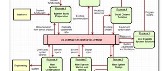
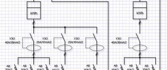
Example of ES wiring
Instruction 2. All numbers for the diagram must be indicated in accordance with the sequence of positions of elements or products on the ES from bottom to top in the direction from right to left. If necessary, it is allowed to change the sequence of assignment of numbers depending on the location of components in the product, the orientation of the passage of signals or the functional sequence of operation.
Instruction 3. Positional articles will be indicated on the diagram near the conventional block (drawn) or on the right side of the products. It is also not allowed to cross a positional value with connection marks, UGO elements or other other marks.
Creation of electrical circuit diagrams.
For those who know at least a little how to work with Microsoft Word, it will not be at all difficult to create an electrical circuit. You just need to select the required element in the library, click on it and it will immediately appear in the document. Now all that remains is to arrange the elements entered in this way as you need on the sheet and connect the connection points of the diagram with lines and the diagram is ready! Don't forget to use standard program tools.
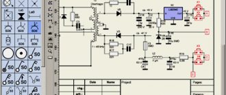
An example of creating a diagram in Microsoft Word can be seen in Figure 6.
Figure 6. An example of creating a diagram in Microsoft Word.
Free software
There are not many Russian-language, easy-to-use, and also free software for creating single-line electrical diagrams on a computer. So, we have created a small rating so that you know which programs are best for drawing power supply diagrams for houses and apartments:
- Microsoft Visio
. Oddly enough, the most popular and, no less important, free program for drawing single-line electrical diagrams on a computer is the vector graphics editor Visio. With its help, even a novice electrician can quickly draw a circuit diagram of a house or apartment. As for the functionality, they are not as advanced as the software that we will provide below. To summarize, we can say that Microsoft Visio is an easy-to-use and, at the same time, free program in Russian for modeling electrical circuits, which is suitable for home electricians. - Compass-Electric
. A more professional software package for designing indoor electrical circuits. Compass has its own database, which stores the names and ratings of all the most popular types of automation, relay protection, low-voltage installations and other circuit elements. In addition, the database contains graphic symbols of all these elements, which will make it possible to create a clear diagram of the power supply or even a separate distribution board. The software is completely in Russian and you can download it for free. - Eagle
(Easily Applicable Graphical Layout Editor). This software package will allow you not only to draw single-line power supply diagrams, but also to independently develop a drawing of a printed circuit board. As for the latter, drawing can be done either manually or without your own participation (in automatic mode). Today there are both paid and free versions of the Eagle program. For home use, it will be enough to download the version labeled “Freeware” (there are some restrictions regarding the maximum usable area of the printed circuit board). The disadvantage of this software package is that it is not officially Russified, although if you try a little, you can find a Russifier on the Internet, which will allow you to draw electrical diagrams of apartments and houses without any obstacles. - Dip Trace
. Another popular program for drawing electrical circuits and creating routes for printed circuit boards. The program is simple and easy to use, and is also entirely in Russian. The interface allows you to design a printed circuit board in three-dimensional form, using a database with ready-made electrical circuit elements. You can evaluate the full functionality of the software only for money, but there is also a stripped-down free version, which will be quite enough for a novice electrician. - «1-2-3 scheme
" A completely free program for drawing electrical circuits on a computer. From the official website you can download it in Russian and the full version. In addition to modeling power supply projects for apartments, houses and other types of premises, in this software package you can easily draw up a distribution board assembly diagram, which will immediately provide the most suitable ratings of circuit breakers, relay protection, etc. A nice addition to this software is a database with stickers that can be printed and pasted in your own distribution panel to graphically designate all circuit elements according to GOST. - AutoCAD Electrician
. One of the free versions of the popular AutoCAD editor is AutoCAD Electrician. Briefly about this software, we can say the following: the functionality is suitable for both beginners and professional electricians working in the energy field. Everything in the interface is simple, you can quickly figure it out. All functions are in Russian, so you can easily use AutoCAD to draw electrical wiring diagrams for your house or apartment. - Elf
. An interesting name for a simple program for modeling power supply circuits in construction drawing. The software package itself is no less interesting and multifunctional. Using the Elf Design program, you can create power supply drawings of any complexity. In addition, the software helps to select circuit breakers of a suitable rating, calculate the cable cross-section for power and current, etc. "Elf Design" is a completely free software package in Russian.
You can see some of the listed programs in video reviews:
AutoCAD Electrical KOMPAS-Electric Visio
In addition to the 7 programs provided for drawing electrical circuits, there are more than a dozen editors in which you can draw up a basic plan for the power supply of a house or apartment for free, but other programs have a more complex interface or problems with the Russian version. We recommend giving preference to representatives of this rating, so as not to waste time in the future searching for localization codes, user manuals, and the like!
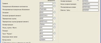
Reading a document
Knowing what kinds of icons there are and understanding what they mean, it will not be difficult to read and understand any circuit diagram. Since a schematic diagram is nothing more than a graphical representation of all its elements included in the device with connecting conductors. It is the fundamental document for the design of any electrical circuit system or electronic device. Therefore, even a novice electrician or radio amateur should be able to read it. It is a correct understanding of the drawing that helps master the basics of design, and helps craftsmen quickly and effectively repair damage.
You might be interested in Description and types of input distribution devices (IDUs)
First of all, the elements that make up the product or system are studied. The diagram shows the main components and their purpose. Each node is studied separately. If there are no accompanying explanations for the diagram describing its operation, its operating principle can be figured out independently on the basis of the drawn details. For this, reference books or datasheets produced by parts manufacturers are used. They usually indicate in detail how their element can be used in an electrical circuit with the types of its inclusion and parameters.
Secondly, attention is drawn to the clarifying information indicated next to each element and key points of the diagram. Thanks to it, it will be easy to determine which part is used in this place or how the signal changes after passing a certain node.
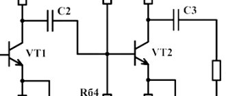
For example, a bipolar transistor has at least three terminals. In this case, to determine its connection to electrical connections, the letter designation of the element base is used. If the type of part is not clear, you should pay attention to its name and serial number in the diagram. Having remembered this information, identify the element, possibly using a specification. This is a separate document or a table indicated next to the diagram containing a list of all components used to construct a device or circuit.
Direct reading of the circuit occurs from left to right and starts from the point where the input signal is supplied to the device. Next, the path of its passage through electrical connections is monitored, right up to the exit of the product or system.