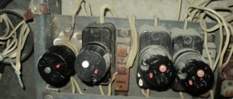
In recent decades, the range of protective electrical devices has been supplemented with residual current devices (RCDs), differential circuit breakers (DIFs), and surge protection devices (SPDs). The listed protection devices make it possible to increase the safety of operation of electrical networks. This material is dedicated to RCD. More precisely, one of the varieties of residual current devices - an electromechanical RCD.
On a note! RCDs are often called residual current devices (RCDs). This name is associated with the principle of operation of protective devices. The design and principle of operation of the UDT will be discussed below.
Purpose of RCD
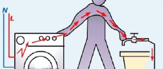
Most current protection devices (fuses, circuit breakers, etc.) protect electrical wiring and electrical receivers connected to it from overload and short circuit currents. Residual current devices perform other functions. Depending on the triggering current, they protect people from electric shock or prevent fire.
Every electrician knows that industrial frequency alternating current flowing through the human body becomes hazardous to health if its value exceeds 0.01 ampere. Currents above 0.1 A are deadly. Therefore, the threshold operating current (setting) of the RCD protecting a person from electric shock is usually selected from the ratings of 10 mA or 30 mA. The first setting is used for damp rooms, children's rooms, and so on. The 30 mA setting applies to normal conditions.
To prevent fires, devices are installed that are configured for differential currents exceeding 300 mA.
Variety of types of automatic machines
Currently, they produce a huge number of types of automatic machines for every taste. To choose among them the best option for a specific electrical network, you need to have an idea of their classification according to functionality. This will make choosing a device much easier. By passing them through a sieve of several of the most important characteristics, you can greatly reduce the list of suitable devices.
By network type and leakage current
Differential circuit breakers according to the type of controlled electrical network are divided into single-phase with a voltage of 220 V and three-phase with a linear voltage of 380 V, respectively, divided into two-terminal circuits for single-phase and four-terminal circuits for three-phase networks.
Depending on the leakage current occurring in the controlled network, difavtomats, like RCDs, are divided into the following categories.
Operating principle of an electromechanical RCD
Residual current devices respond to leakage currents that occur when the insulation of electrical wiring is broken or when a person touches live parts that are energized. The main feature of leakage currents is that they upset the balance (equality) of currents flowing through the phase wires and the neutral wire.
A differential transformer is used to detect leakage. Structurally, it consists of:
- a ferrite ring serving as a magnetic circuit (core);
- primary windings, which are phase conductors and a neutral wire passed through the core;
- secondary (measuring) winding.
In the absence of leakage currents, the total magnetic flux created in the transformer core by the primary windings is zero. In this case, there is no EMF in the secondary winding. If a leak occurs, the balance of currents is disrupted and an EMF begins to be induced in the secondary winding. A potential difference occurs at the terminals of the measuring winding. The higher the leakage current, the higher the potential difference.
On a note! Electrical protection based on comparison of currents is called differential current protection .
The voltage removed from the secondary winding of the differential measuring transformer is supplied to the threshold organ (comparison device). The threshold organ generates a shutdown signal when the leakage current reaches the set value.
A polarized relay is used as a threshold element in electromechanical disconnecting devices. In an electronic RCD, the comparison device is a DC amplifier made on an operational amplifier chip.
How to determine the type of RCD
Before purchasing and installing a protective device, you must accurately understand its type and design features. This will allow you to make the right choice and ensure the required level of security for the given conditions. There are several ways to reliably determine the type of RCD in question.
All actions to determine the type of RCD can only be carried out if the devices are disconnected from the power supply line.
According to the diagram shown on the RCD body
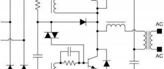
All types of protective devices on the housing, in addition to markings, have an electrical circuit. On electromechanical RCDs it has the following form:
- differential transformer (oval);
- relay (square).
The transformer and relay are connected by straight lines, indicating a direct electrical connection. There should be no more straight and unbroken lines on the diagram. Direct intermittent is a mechanical connection between a relay and a contactor.
In electronic RCDs, between the relay and transformer symbols there is a triangle indicating an amplifier. There should also be unbroken lines connecting the power supply line to the amplifier (triangle).
Determining the type of RCD according to the diagram on the housing is the most reliable. But to use this method, you must have at least basic skills in reading electrical diagrams.
Battery testing
Any DC source is suitable for this method: battery or accumulator.
This method will only work on a device with a response threshold of no more than 30 mA.
The sequence of actions will be as follows:
- the phase input and output of the RCD are connected via wire;
- the wires are connected to the poles of the battery.
If the RCD is triggered when the battery is connected, then this device is electromechanical. If the device does not work, then it makes sense to change the polarity of the connection to the battery. The electronic RCD will not trip with both power source connection schemes.
In addition, testing with a battery will also help identify the type of current that the device is designed for. Class A devices (pulsating direct and sinusoidal alternating current) will operate with all battery connection methods. Class AC (sinusoidal alternating current) will operate only with one battery connection option.
Magnet testing
It is necessary to cock the RCD and run a permanent magnet along the device body. In this case, the electromechanical device will work, but the electronic device will not.
Electromechanical UDT device
Electromechanical RCDs consist of the following main parts:
- housings;
- contact system consisting of terminals to which power wires are connected, moving and fixed contacts used for switching;
- instrument transformer and rectifier;
- polarized relay;
- mechanical shutdown systems (release);
- electric arc extinguishing systems;
- test button and resistor.
Purpose of some elements
Polarized relay
The executive element in electromechanical differential current devices is a polarized relay. A polarized relay belongs to the class of bistable DC relays. It can be either in the off or on state in the absence of voltage on its winding. In the RCD, the winding of the polarized relay receives rectified voltage from the measuring transformer. When the threshold value is reached, the relay switches, which is mechanically connected to the release. As a result, the UDT is turned off.
TEST button
Unlike circuit breakers and other protective devices, RCDs have the ability to check the functionality of the device. The test is performed by pressing the “Test” button. This button, together with a specially selected resistor, forms a chain that simulates the occurrence of leakage current. The ends of the chain are connected to the neutral and phase wires. The string conductors do not pass through the ring core of the differential transformer. Therefore, during the test, the balance of magnetic fluxes in the measuring system is disrupted. The resistor value is chosen so that the artificial leakage current is equal to the rated operating current of the differential protection.
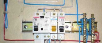
Step-by-step installation instructions
Self-installation is performed in the following order:
- Develop and draw a diagram. It is necessary to think over how to connect each core, so a simple single-line one is not suitable.
- The contacts of the input circuit breaker are opened. Work may only be carried out on a de-energized line. Make sure there is no voltage using an indicator screwdriver.
- The device is mounted on a DIN rail. To do this, use a screwdriver to bend the clamp on the back side.
- The ends of the cores are stripped by 0.5 cm and fixed in the RCD terminals. Color coding must be observed. Stranded conductors are pre-crimped with an NShVI type tip or tinned.
- The device is marked in a convenient way to understand which consumers are connected through it.
In electrical engineering, it is customary to place a connection diagram in the panel.
Installation of the RCD is carried out in a certain order.
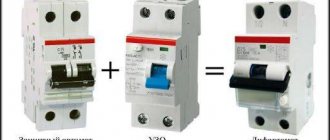
The difference between an electronic RCD and an electromechanical UDT
Electronic and electromechanical protection devices differ only in the type of threshold device. As noted above, electronic protection devices use an electronic amplifier as a threshold device, which generates a shutdown signal. This signal is sent to a conventional relay, which acts on a mechanical release. Electronic components, unlike electromechanical relays, are cheaper and have less technological variation. Therefore, an electronic RCD, as a rule, costs less than an electromechanical protection device.
People who have not previously encountered residual current devices often ask the question: how to distinguish an electromechanical RCD from an electronic one? Devices can be identified by markings on the front of the device. For all RCDs on the body you can see a symbolic image of a differential transformer. It is depicted as an ellipse enclosing power conductors. A symbolic communication line is drawn from the transformer going to the comparison device. The comparison device is depicted as a rectangle or triangle. If a triangle is drawn, then this is an electronic RCD. If the rectangle is an electromechanical device.
Important! If one or all of the images of the phase conductors connected to the moving contacts have bends in the form of an arc or a rectangular protrusion, then you are dealing with a circuit breaker. These bends represent the electromagnetic and thermal release respectively. If a measuring transformer and a comparison device are added to the “bends”, then this is a difavtomat.
On a note! All RCDs always have an even number of poles. Devices used in a single-phase network have two poles - phase and zero. Three-phase UDTs respectively have 4 poles. Zero terminals are always marked with the Latin letter “N”.
The eternal dispute about RCD
On electricians forums, debates continue on the topic: which protection device is better to use, electronic or electromechanical RCD?
In principle, there are no functional differences between devices with different threshold devices. Both types of differential current devices successfully perform their functions. But meticulous researchers have noticed one feature that the electronic RCD has. An op amp requires power to operate. It is taken from the input terminals of the protection device. Therefore, in the event of a break in the zero or phase supplying the electronic circuit, the device loses its functionality. An electromechanical RCD is free of this drawback, since the actuator is powered from the secondary winding of the transformer. Therefore, if the neutral wire breaks, the “electromechanics” will still work in the event of a phase leak.
Connection diagrams for a single-phase RCD: 3 options for use in an apartment
The protection module in the apartment panel can be mounted on:
- input for monitoring all working equipment connected to the wiring;
- one problem line, for example, for a bathroom or kitchen with a high degree of humidity;
- several highways with socket groups.
Introductory RCD: protection of all wiring in the apartment panel
The protective shutdown device at the entrance to the apartment is installed directly behind the meter and the input circuit breaker.
An example of the location of the protection modules shown in the photograph of the electrical panel is supplemented by an explanatory diagram. To enter it, a conventional single-phase circuit breaker is used.
It only breaks the potential of the fault current phase. This is quite acceptable for most tasks that arise in matters of household wiring safety.
A circuit with a two-pole input circuit breaker is created according to the same principle, except that the zero potential passes through its second line to the input of the input RCD.
After leaving the residual current device, the zero potential is connected to a separate insulated busbar N. From it, cables are routed through the conductors to consumers.
The PE conductor protective lines are mounted using their own PE busbar. The corresponding core from the input cable is connected to it and the outgoing lines to all consumers are assembled without any breaks.
Technical characteristics of the RCD: rated current and leakage value - how to choose the right one for the input module
The 2 listed parameters are factory built into the design of any module. We will not be able to change them after purchasing it. Therefore, it is important to choose them correctly before purchasing.
The rated current and leakage response setting are marked directly on the protection housing.
How to choose an RCD based on rated current
This value characterizes the current strength that the internal circuits of the unit can normally withstand without damage, for example, with a value of 40 amperes, as shown in the picture.
If more current flows through the internal protection circuit, it will simply burn the windings, wires, and insulation. This cannot be allowed.
Each residual current device is connected through an individual circuit breaker with a lower rated current by one step of the standard series.
The residual current module is installed behind the circuit breaker. Then it is completely de-energized after the power contacts of the machine are broken.
Based on this principle, a machine with a current of 32 A for an input RCD of 40 amperes was selected for the upper circuit. Its setting for short circuit load and overload saves our module from burning out in any accident.
The differential automatic machine has universal capabilities. It combines in its design the capabilities of an RCD and a circuit breaker with balanced electrical parameters of the rated current.
The cost of the difavtomat is slightly higher than the components of the RCD and the machine together, but its use saves space in the apartment panel, which is often quite justified.
How to choose an RCD based on leakage current
Currents flow through almost any layer of insulation. It’s just that materials with high dielectric properties have very small ones due to high electrical resistance.
Damaged insulation has low confining capacity. High currents flow through it.
PUE regulates the total leakage current (differential) through the insulation. It should never exceed a value that is safe for humans.
There are special laboratory instruments that allow you to measure leakage current through the insulation of electrical wiring. When they are absent, an approximate calculation is performed using the proposed method.
For ordinary premises, a residual current device with a safe differential current of 30 mA is selected. In a humid environment, such as a bathroom or kitchen during cooking, its value drops to 10 or 6 mA.
At the entrance to the building, it is permissible to install a residual current device with a rating of 100 mA.
If the total leakage current of the electrical wiring exceeds the permissible differential current level for the RCD by more than 33%, then it is necessary to consider the issue of completely replacing outdated wires and cables.
An input RCD of 100, 300 or 500 mA is not capable of saving a person from electrical injury. Its task: to prevent fire due to ignition of electrical wiring.
The scheme of using one protection with a body for comparing the phases of currents at the input is simple and economical, but it significantly complicates troubleshooting after it is turned off.
RCD for a bathroom: example of choosing a protection module for one consumer
An option for placing a protective shutdown inside an apartment panel is shown in the photo below.
The connection diagram of the protection module for one separate line (bathroom) with the location of the phase and neutral lines is shown in more detail in the general picture for apartment wiring.
The circuit breaker of this line, like the others, is powered from the assembly behind the input circuit breaker.
I would like to draw your attention to how the working zero bus is connected here and its differences from the method chosen for the circuit with an input module.
The working zero is supplied from the input cable directly to the meter, and from it is discharged to bus N. From it, wiring is carried out to all consumers with cables of outgoing lines.
The working zero is supplied to the bathroom sockets through a separate power contact of our protection.
Installation of the PE busbar is carried out according to the previous option without changes.
In this scheme, the internal structure of the module is protected from exceeding the rated current (16 amperes) by its own circuit breaker (rated 10 A).
When the protection is triggered, troubleshooting is simplified by checking the insulation condition on the line from the power contacts of the module to the working element of the connected consumer.
Group RCD: economical protection of several outgoing lines
Installing an individual module for each individual consumer is the most justified solution in matters of ensuring safety and locating the location of a malfunction.
However, this installation scheme is the most costly and expensive. It requires the use of a fairly capacious apartment panel and a large number of RCD modules or differential circuit breakers. It takes a lot of money to buy them.
Group RCD allows you to save them. It is simply connected to several outgoing lines, placing a separate unit in front of individual circuit breakers.
It is convenient to install them inside the apartment panel in separate groups. This technique provides clarity during operation and repair.
The connection diagram for a group RCD to several outgoing lines is shown below.
Here, the protection of the group module at a rated current of 50 amperes is performed by a 40A input machine.
With such a circuit, novice electricians make an erroneous calculation, selecting the rated current of a group RCD as the sum of the ratings of the connected loads.
For example, in the diagram, all consumers are powered through 32, 25 and 16 ampere circuit breakers. Their total sum is 32+25+16=73. It is pointless to look for protection with such a denomination or more.
This issue is solved more simply: the input circuit breaker in this apartment wiring has already been selected for 40 amperes. He is obliged to turn off large currents, while simultaneously protecting the group RCD.
Therefore, its rating is quite enough to choose one step more from the standard current series: 50 amperes.
Differences in the configuration of the working zero circuits for the group RCD circuit
The considered circuit combines both of the above-discussed options for forming chains for connecting to the N bus:
- before the group RCD there is a second design used for a single line;
- after it, its own additional bus N1 is created, separated from the general chain by the contacts of the group module.
The use of the additional N1 bus greatly facilitates the search for leakage currents in outgoing lines that occur when the insulation of zero potential wires is damaged after the protection is turned off.
The installation of the PE bus and the wires to it does not change.
How to choose the right RCD
We discussed the issue of using electronic and electromechanical devices above. They also talked about choosing a setting for different types of premises. There is one more parameter that should be taken into account when choosing a UDT. This parameter is the rated operating current. That is, the current that the RCD can withstand for an unlimited amount of time. When choosing a working “nominal value” you can follow a simple rule. The operating current must be no lower than the operating current of the machine, which protects the supply line from short circuit and overload.
Common Mistakes
Most often, home craftsmen commit the following incorrect actions:
- The contacts are mixed up so that the currents in the differential transformer coils flow in one direction. To avoid errors, you should adhere to the general standard: the phase and “zero” on the input side are connected to the upper terminals L1 and N1, the wires to the apartment are connected to the lower terminals L2 and N2.
- The buses are connected below the group RCDs. The circuit protected by the device must be isolated from others. Busbars are installed above group RCDs and automatic machines.
- Neutral conductors from different groups are confused.
- The product is selected incorrectly based on its rated current. It should be one step higher than that of an automatic machine.
- During the installation process, the sockets are connected to the protective grounding conductor with the neutral.
Home craftsmen confuse contacts and neutral conductors from different groups.
During operation, it is necessary to periodically check the device for operability using controlled leaks or the Test button.
How to properly connect residual current devices
When connecting leakage current protection devices, several basic rules must be observed.
First and most important. RCDs and automatic devices must be operated in networks with a solidly grounded neutral with a separate grounding wire (three-wire or five-wire system). In this case, the housings of all electrical receivers protected by devices from leakage currents must be reliably grounded. Grounding can be carried out through the socket contacts or with a separate bolt-on wire.
Dangerous! Never use the neutral wire as grounding. Only a separate land!
Second. It is necessary to ensure that the wires are connected correctly. Zero should be connected to the terminals marked with the letter “N”, and phases to the phase terminals. This rule, which at first glance is not obvious, is associated with connecting the test button and the electronic protection circuit.
Third. Conductors of the same name protected by different RCDs cannot be connected to each other. This mistake is often made by inexperienced electricians when they use a common zero for several socket blocks. Such a connection, when connecting a load, immediately triggers the protection.
Verification methods
The RCD is equipped with a Test button. After pressing it, the working device turns off. This method is intended to check the condition of the product, but not the correct connection. In the event of an error, a working RCD opens the circuit when the Test button is pressed, but may not respond to differential current.
To be 100% sure that the device is working, a controlled leak is performed. To do this, the phase is connected through a variable resistor and an ammeter to the ground or neutral conductor above the RCD. Only a licensed specialist has the right to perform such work.
How to quickly check an RCD without connecting to the network
Each leakage current protection device has a test button. With its help, it is easy to carry out periodic checks of the UDT during operation. To test a large batch of disconnecting devices that are not connected to the network, you can use a regular 1.5 V AA battery.
If it is connected to the same poles (for example, to terminals 1-2), a working device will work instantly, since the current pulse during connection will not be balanced by the reverse current. RCDs with a rated differential current of 10 or 30 mA are triggered even by a dead battery.
Protection options for single-phase network
Manufacturers of powerful household appliances mention the need to install a set of protective devices. Often, the accompanying documentation for a washing machine, electric stove, dishwasher or boiler indicates which devices need to be additionally installed into the network.
However, more and more often several devices are used - in separate circuits or groups. In this case, the device in conjunction with the machine(s) is mounted in the panel and connected to a specific line
Considering the number of different circuits serving sockets, switches, equipment that load the network to the maximum, we can say that there are an infinite number of RCD connection schemes. At home, you can even install a socket with a built-in RCD.
Next, we will consider the popular connection options, which are the main ones.
Option #1 – general RCD for a 1-phase network.
The location of the RCD is at the entrance of the power line to the apartment (house). It is installed between a common 2-pole circuit breaker and a set of circuit breakers for servicing various power lines - lighting and socket circuits, separate branches for household appliances, etc.
If a leakage current occurs on any of the outgoing electrical circuits, the protective device will immediately turn off all lines. This is, of course, its disadvantage, since it will not be possible to determine exactly where the malfunction is
Suppose that a current leak occurs due to contact of a phase wire with a metal device connected to the network. The RCD trips, the voltage in the system disappears, and it will be quite difficult to find the reason for the shutdown.
The positive side concerns savings: one device costs less, and it takes up less space in the electrical panel.
Option #2 – general RCD for 1-phase network + meter.
A distinctive feature of the scheme is the presence of an electricity meter, the installation of which is mandatory.
Current leakage protection is also connected to the machines, but a meter is connected to it on the incoming line.
If it is necessary to cut off the power supply to an apartment or house, turn off the common circuit breaker, not the RCD, although they are installed nearby and serve the same network
The advantages of this arrangement are the same as the previous solution - saving space on the electrical panel and saving money. The disadvantage is the difficulty of detecting the location of a current leak.
Option #3 – general RCD for a 1-phase network + group RCDs.
The scheme is one of the more complicated variations of the previous version.
Thanks to the installation of additional devices on each operating circuit, protection against leakage currents becomes double. From a security point of view, this is an excellent option.
Suppose an emergency current leak occurred, and the connected RCD of the lighting circuit did not work for some reason. Then the general device reacts and turns off all lines
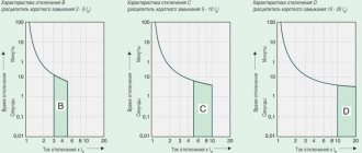
To prevent both devices (private and common) from triggering at once, it is necessary to observe selectivity, that is, when installing, take into account both the response time and the current characteristics of the devices.
The positive side of the scheme is that in an emergency one circuit will turn off. It is extremely rare for cases where the entire network goes down.
This can happen if the RCD installed on a specific line:
- defective;
- out of order;
- does not match the load.
To prevent such situations from arising, we recommend that you familiarize yourself with the methods of testing RCDs for functionality.
Disadvantages - the electrical panel is overloaded with many similar devices and additional expenses.
Option #4 – 1-phase network + group RCDs.
Practice has shown that the circuit without installing a common RCD also works well.
Of course, there is no insurance against failure of one protection, but this can be easily fixed by purchasing a more expensive device from a manufacturer you can trust.
The circuit resembles the option with general protection, but without installing an RCD on each individual group. It has an important positive point - it is easier to determine the source of the leak.
From the point of view of economy, wiring several devices loses - one common one would cost much less.
If the electrical network in your apartment is not grounded, we recommend that you familiarize yourself with the diagrams for connecting an RCD without grounding.
RCD marking
Each RCBO must be permanently marked indicating all or, for small sizes, part of the following data:
- Name of the manufacturer or trademark (brand);
- Designation of type, catalog number or series number;
- Rated voltage(s);
- Rated frequency if the RCCB is designed for a frequency other than 50 and/or 60 Hz
- Rated current;
- Rated residual current;
- Settings of the tripping differential current for RCCBs with several values of the tripping differential current;
- Rated maximum making and breaking switching capacity;
- Degree of protection (only if it differs from IP20);
- Working position, if necessary;
- Rated maximum differential making and breaking capacity, if it differs from the rated maximum making and breaking capacity;
- Symbol for type S devices;
- An indication that the RCCB is functionally dependent on the mains voltage, if this is the case;
- The designation of the control device control body is the letter T;
- Connection diagram;
- Performance characteristic in the presence of differential currents with DC components.
The marking shall be applied either directly to the RCCB or on a plate(s) attached to the RCCB and shall be located so as to be visible after installation of the RCCB.
If the dimensions of the devices do not allow all the above data to be applied, then at least the markings according to points 5), 6), 14) must be visible after installation. Information on points 1), 2), 3), 10), 11) and 15) can be printed on the sides or rear surfaces of the device and be visible only before installation. Information on point 15) can be applied to the inner surface of any cover that needs to be removed to connect the power wires.
Information on other points should be provided in the operational documentation and manufacturer’s catalogs.
Terminals intended exclusively for connecting the working neutral conductor circuit must be marked with the letter N. Terminals intended for the neutral protective conductor, if any, must be indicated by a symbol (according to GOST 29322).
Labeling example
1 - From 16 - we have a differential in front of us. automatic circuit breaker with a shutdown current of 16A. 2 - Setting for differential current - 100 mA. 3 — The device is designed for 230 V networks 4 — Overvoltage protection. If the network voltage increases above 270 V, a shutdown will occur. 5 - Diff. AC type automatic machine, i.e. responds only to the alternating current component.
Designations in email diagrams
At the moment, GOST does not have any recommendations regarding the graphic symbols of RCDs and differential circuit breakers. The images of symbols used in the diagrams differ from each other.
Therefore, in this article, I want to give my recommendations and propose a designation option for RCDs and differential circuit breakers, which, in my opinion, will correspond to the functional purpose of these electrical devices.
Functionally, an RCD can be defined as a high-speed switch that responds to differential current - leakage current in the conductors supplying electricity to the protected electrical installation.
note
A current transformer is used as a differential current sensor and the main functional element of the RCD, which is often called a zero-sequence current transformer (which is not entirely correct, but I think it’s acceptable).
From the above it follows that the image of the RCD symbol must consist of the designation of the switch and the zero-sequence current transformer, the signal from which (zero-sequence current) affects the disconnection mechanism of the contact group of the device.
The following notation suits this requirement:
A differential circuit breaker differs from an RCD in that it combines two devices, a circuit breaker and a residual current device, in one electrical device. For this reason, the following notation can be used:
| Using the common circuit breaker designation |
| Using the circuit breaker designation according to GOST 2.755 |
The alphanumeric designation of RCDs and differential circuit breakers, in my opinion, can be applied to the diagram as follows:
Where Q1 and QF1 denote the functions of the switch and circuit breaker, respectively, and the serial number of the device in the circuit. The residual current value indicates the function of the residual current device
The second alphanumeric designation option, which is often used: QD1
for RCD and
QFD1
for differential circuit breaker. And although according to GOST 2.710 the code of the letter D denotes integrated circuits, there is no more suitable symbol in this GOST. We will assume that D, from the word differential.
This version of the conventional graphic designations of RCDs and differential circuit breakers, until any recommendations are published in regulatory documents, in my opinion, is the most acceptable. Therefore, I decided to include stencils of the electrical devices discussed above in the Electrical Circuit Drawing Kit.
Source: https://elektroshema.ru/2009-02-05-22-57-45/ugo-2/64-uzo.html
Basic mistakes when connecting an RCD
When connecting an RCD, many people make common mistakes that can have very serious consequences for a person. To avoid them, follow these rules:
- the input terminals of the residual current device must be connected only after the corresponding circuit breaker; direct connection to the network is unacceptable;
- observe the correspondence of neutral and phase contacts, their designation is specifically indicated on the housing;
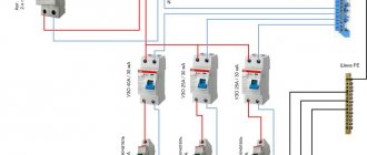
- when installing wiring, carefully follow the diagram, especially for objects with branching, a large number of connected objects and several RCDs for them;
- if there is no grounding conductor in an apartment or house, then it should never be replaced with a wire thrown over heating radiators or water pipes; grounding must be made in accordance with the rules;
- pay attention to the performance characteristics of the purchased devices (rated operating current and shutdown current) and their compliance with the network parameters, for example, if a current of 50A can flow in the line, then the device should be selected at least 63A.
To protect yourself during connection, follow basic electrical safety rules.
RCD design
From a technical point of view, the design of the RCD-D is nothing complicated or new compared to the designs of automatic circuit breakers. Moreover, Russian manufacturers began and mastered the production of these products based on VA assault rifles. An example is the well-known UZO22 from the Signal plant, produced on the basis of the VA66-29 and VA88-29 circuit breakers. They have the mechanics of the free release, the coil, contacts, arc arresters - everything is the same as the VA. You can learn more about their design, operating principle and structure in the article circuit breaker (household). The only difference is in the module controlled by differential current (MCO), the design and operation of which are described above. The same can be said about RCDs produced on the basis of foreign automatic machines.
Purpose
The primary purpose of an RCD is to guarantee the protection of the human body from the effects of electricity resulting from damage to the insulation of electrical equipment and electrical lines. A person who accidentally comes into contact with such equipment is exposed to electric current, and it is necessary to prevent injury and even death, which is why this device is needed.
Before installing this device, you need to understand what it is.
RCDs in electrical applications are used for the following purposes:
- Connecting electrical consumers is a switch function.
- Creating a reliable electrical circuit for the rated current that does not cause false operations.
- Possibility of de-energizing (switching off) electrical consumers under load.
- Switching off the controlled object when the set differential current value is reached.
If the leakage is unacceptable, the device disconnects the damaged part of the circuit in less than a second. The device is not protected from short circuit; it requires the mandatory installation of a circuit breaker.
The existing types of RCDs are electronic and electromechanical RCDs. The advantages of an electromechanical device are that it remains operational when the line is de-energized. The occurrence of a leak will cause the device to operate, and protect people from electric shock.
There is a simple way to distinguish an electronic type RCD from an electromechanical one: you need to check it in test mode, if it works in the absence of external voltage, then it is an electromechanical product, otherwise it is an electronic product.
A type of RCD includes the RCD-D device, which is equipped with an additional, autonomous power supply, which allows it to remain operational even if the main voltage is turned off. This type allows for reliable operation.
Connecting an RCD in a two-phase network
Two-phase power refers to non-standard connections, where a converted old-style 127 V transformer was reconnected into a triangle for modern 220 V consumers, which are powered by linear voltage from it.
Rice. 4: Connecting an RCD in a two-phase system
To connect a residual current device to a two-phase circuit, it is necessary to disconnect both wires at the input to the panel, since each of them is under potential. Then each of the phases is connected to the corresponding phase terminals and neutral terminals, further observing their polarity. Unlike a single-phase system, circuit breakers at the output of the RCD must be installed for each line, or they can be replaced with one two-pole one.
RCD design
From a technical point of view, the design of the RCD-D is nothing complicated or new compared to the designs of automatic circuit breakers. Moreover, Russian manufacturers began and mastered the production of these products based on VA assault rifles. An example is the well-known UZO22 from the Signal plant, produced on the basis of the VA66-29 and VA88-29 circuit breakers. They have the mechanics of the free release, the coil, contacts, arc arresters - everything is the same as the VA. You can learn more about their design, operating principle and structure in the article circuit breaker (household). The only difference is in the module controlled by differential current (MCO), the design and operation of which are described above. The same can be said about RCDs produced on the basis of foreign automatic machines.
Main characteristics of RCD
Let us highlight the main technical characteristics that you need to pay attention to when choosing an RCD for a residential premises before starting repairs. These include:
- number of poles: two-pole and four-pole RCD;
- mains voltage: 220 or 380 V;
- rated load current of the network, it ranges from 16 to 100 Amperes;
- conditional short circuit current – can vary from 3 to 15 kA. This value shows the reliability of this RCD, and its ability to resist when a short circuit occurs;
- device design – electronic or electromechanical;
- the principle of its operation (Ac, A, B, S or G);
- its switching capacity.
Switching capacity - denoted by Im; represents the maximum value up to which this device will respond. This value must be at least 500 A.
Attention! When choosing an RCD, keep in mind that it is better to purchase electromechanical devices, as they are considered more reliable and cheaper.
For a regular voltage network of 220 Volts, conventional two-pole devices are optimal. But for a three-phase network with a voltage of about 380 V, you should choose the four-pole RCD devices we have already mentioned.
Basic elements and characteristics of RCD
Modern protective devices are not recommended for installation in houses with old wiring. In such premises, current leakage often occurs, which leads to instability of the entire network and significant voltage surges. As a result, the RCD may trip for no reason at all.
Typically, in residential premises, RCDs are installed to protect against current leakage in kitchens and bathrooms, since it is in these rooms that there is high humidity. These places are most saturated with electrical appliances, where current leakage can occur.
Electromechanical automatic or electronic – which is better?
Just like RCDs, differential circuit breakers are manufactured either with an electromechanical shutdown or with an electronic shutdown device. An electromechanical device does not require additional energy to operate. Energy is taken from the leakage current source. Therefore, the differential transformer that registers these currents in electromechanical devices is large. The transformer needs such dimensions to turn a small signal into a voltage sufficient to operate the device. The large size of the transformer increases the overall dimensions of the entire device.