Operating principle of an inductive electricity meter
Naturally, with constantly changing loads, monitoring the readings of a wattmeter with a stopwatch would be extremely impractical.
Therefore, they came up with a device (electricity meter), where the moment of force arising from the electromagnetic interaction of voltage and current coils is used to rotate the drive of the counting mechanism. Theoretically, we can assume that the voltage in the network does not change, which means that the change in the strength of the electromagnetic interaction of the coils is directly proportional to the current of the connected load. Induction counter - inside view
The counters use an aluminum disk as a drive for the counting mechanism, where voltage and current coils induce eddy currents, the electromagnetic field of which interacts with the magnetic fields of these coils, creating a torque.
Therefore, electromagnetic mechanical counters are also called induction counters.
. In an induction electric meter, the magnetic circuits of the current and voltage coils are placed at an angle of 90º and form a gap in which an aluminum disk is placed, which makes it possible to create a moment of force in it for its rotation.
Induction electricity meter device
It is known from school physics that a force constantly acting on a body without interference causes it to accelerate to infinity. Thus, in an ideal counter mechanism (without friction), constant power would spin the disk to infinite revolutions. Therefore, the electric meter device has a permanent magnet to brake the aluminum disk of the counting device drive.
Since aluminum is a non-magnetic metal, the braking force depends only on the speed of rotation of the disc. Correctly setting the balance between the accelerating force of the disk and the braking torque allows you to establish the dependence of the rotation of the counting mechanism drive only on the power consumption and eliminate self-propulsion and rotation in the opposite direction. Induction single-phase and three-phase electric energy meters, which have two aluminum disks on one shaft, operate on this principle.
Three-phase induction electricity meter
Advantages and disadvantages of induction electricity meters
The counter mechanism described above has been used in various models of electricity meters for many decades due to its simplicity and reliability
designs. A voltage coil having many turns, wound with a thin wire, with a diameter of 0.06 - 0.12 mm, is highly resistant to long-term overvoltages - very often single-phase electric meters were under a voltage of almost 380V due to a zero break, but subsequently continued to work properly.
The current coil has several turns with a cross-section sufficient to withstand the short-circuit current. Since induction electricity meters do not contain other electrical elements or radio components, they are very resistant to voltage surges and the electromagnetic influences of lightning strikes. A simple and cheap counting mechanism, consisting of a worm gear on the shaft of an aluminum disk and a digital drum, allows induction meters to serve regularly for decades in difficult climatic conditions.
A simple device for the counting mechanism of an induction electric meter
Due to imperfect design, friction and aging of mechanisms, induction electricity meters have significant disadvantages:
- low accuracy class;
- large error, increasing at low load currents;
- significant own electricity consumption;
- lack of reactive energy metering for household meters;
- Electrical energy is taken into account only in one direction;
- there is no protection against hacking, interference with work and theft of electricity.
The seal on an outdated induction electric meter is the only protection against unauthorized access to the inside of the housing
Most of the disadvantages of induction meters described above benefit their owners, since electricity is metered with an error that is beneficial for the recipient. Many ways have been invented to deceive an induction meter. Therefore, many electricity suppliers are trying to replace outdated, unprofitable electricity meters for their consumers with new, more accurate hybrid or electronic electricity meters. In some countries, obsolete inductive electricity meters are forced to be replaced free of charge.
Outdated and unprofitable induction meters for electricity suppliers are being actively phased out
Induction meter design
Single-phase induction meter
The main components of an induction electric meter are voltage and electric current electromagnets. When they interact together with the magnetic circuits included in them, an electromagnetic field appears. Through the transmission device, the field acts on the aluminum rotating disk.
The current electromagnet experiences heavy loads during operation, so its winding is made of large-section wire. The number of turns does not exceed thirty. The wire is evenly wound on two magnets, which are connected in series to the network using clamps.
The voltage coil is connected in parallel to the network and creates an electromagnetic field directly proportional to the effective voltage. The coil winding is made of thin wire with a cross section of 0.1…0.15 mm². The number of turns can reach 12,000, which makes it possible to create an inductive reactance greater than the active one. This device allows you to reduce energy consumption when the meter is operating.
All components of a mechanical single-phase electric meter are housed in a plastic housing. Data on electricity consumption for the current period are displayed on a digital drum. The intensity of energy consumption can be determined by the speed of rotation of the disk.
How does an electric meter work?
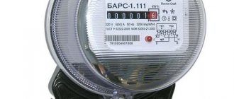
The device of a single-phase direct-connection electric meter, Energomer, will now be clearly visible in the photographs. Let me remind you that his appearance is in the first photo of the article.
There are usually 2 seals on the meter, one protects the meter terminals from unauthorized access, the second protects the electronic circuit of the meter. These seals are no longer on my meter.
Let's take a closer look at the terminals.
The terminals are clamping and hold the stripped wire well along its entire length.
Now the most interesting thing is to open the meter housing:
Energy meter tse6807p. Front panel removed
Energy meter counter. Removed cover, photo 2
We take out the guts and see that the electric meter circuit consists of three main parts:
This is 1) a stepper motor with numbers attached to its axis, 2) a board with a controller and 3) input terminals. As you can see, everything is Chinese (I hope, except for the terminals), which is why the price of such a meter is 650-750 rubles.
Terminals and board with controller. Everything is upside down, so the phase terminals of the meter are on the right, zero terminals are on the left, not as we are used to seeing.
The white and green wires are the output of the measuring shunt. The same shunt on which the voltage, proportional to the current through the phase terminals, “settles”. This voltage is supplied to the inputs of the board KT1 and KT2 and is supplied to the controller for processing.
Also, power for the controller is taken from the phase terminal; this is the yellow wire. Power supply is transformerless, through a capacitor, rectifier and 5VDC stabilizer.
The zero terminal is used to take the second pole to power the meter. And also in order to ensure connection, and to limit malicious schemes for turning on the meter.
From the output of the controller board through points M1.1 and M1.2, pulses are sent to the stepper motor. The one that is braked using a magnet. The pulse frequency is proportional to the current, and is additionally indicated by an LED.
This LED is used to check and verify the meter. Count the number of pulses in (for example) 5 minutes, and look at the correctness of the readings on the front panel.
The controller contains a program that generates pulses for the operation of the stepper motor.
Here is a slightly larger photo of the meter printed circuit board:
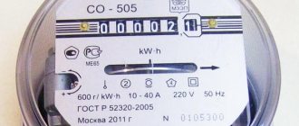
Markings on electricity meters
In addition to the types of meters, there are several more nuances that you should know. Any electric meter has a certain marking, conventionally designated by letters and numbers.
Fig.6. Symbols on the electric meter
| Designation | Explanation |
| WITH | Device type (meter) |
| A, R | Type of energy taken into account (active energy/reactive energy) |
| ABOUT | Single phase meter |
| 3, 4 | Number of phase wires in the network (four-wire/three-wire) |
| U | Versatility |
| AND | Type of measuring system (induction meter). Next there may be a three-digit number, which indicates the design of the meter (the design of the meter can be induction or electronic). |
| T | Tropical meter type |
| P, M | Type of execution (direct-flow - if there is no connection to a transformer / modernized). Further, there may be abbreviations such as “380/220 17A, 2001,” which means operating voltages in the wires, maximum current flow and year of manufacture. Also at the end of the inscription there may be a serial number. |
As for the accuracy class of the electric meter, these parameters determine the accuracy of the readings of consumed electricity. Apartments, as a rule, have class 2.0 meters installed, but they can be higher. What does this mean? And the fact is that your electric meter can take into account 2% more or less electricity from its own power. Or, more simply put, the meter error. The smaller the number, the smaller the error. In general, in domestic conditions, an electric meter of class 2.0 is sufficient. Higher accuracy classes are more likely to be needed in enterprises where greater energy power is needed.
So, today we don’t have to limit ourselves in choosing electricity meters. Each of them has its own specific features and functions. In this article, we examined the main features of these devices and the principles of their operation, which will help you navigate the variety of choices.
Design and principle of operation of the electric meter
The principle of electricity metering is the same in devices of different types, but according to their design they are divided into induction and electronic.
Induction or electromechanical meter
Induction meters contain an aluminum disk that is rotated by two coils:
- voltage, connected in parallel to the load and measuring the network voltage;
- current connected in series with the load.
The higher the current or voltage, the faster the aluminum disk rotates, transmitting rotation through a worm gear to a mechanical digital display. To reduce the rotational inertia of the disk, there is a permanent magnet inside the device, which slows it down with its field.
Electronic meter device
An electronic electricity meter converts the measured power into an analog signal and, subsequently, into a digital one.
The main part of this device is a microcontroller that keeps track of consumed electricity. It transmits a signal to a liquid crystal display or electromechanical display, as well as to the ASKUE system (automated system for monitoring and accounting for electricity).
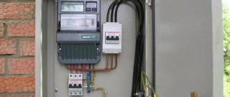
Installation
First you need to decide on the mounting location of the device and purchase the necessary tools.
Stores sell both complete kits for installing the meter and individual parts. The choice of materials depends on the model of the device and the connection features.
The counter must be positioned vertically. The mounting location can be a wooden (metal) sheet or a special protected box. The device must be located in the area of free visual control.
Before installation, you should study the general wiring diagram.
This will allow you to correctly determine the type and number of circuit breakers, as well as the power of consumer groups. This is important: you are prohibited from performing the installation yourself without permission.
Schematic diagram of an electric meter
Schematic diagram of an electricity meter on the AD7755 chip
The operating diagram of all types of electrical appliances has no fundamental differences, they are all similar.
Several simple sensors are used to measure power:
- Voltage sensors whose operation is based on a well-known divider circuit.
- Current sensors based on an ordinary shunt through which a phase of the electrical main passes.
The signal recorded by these sensors is small, so it needs to be amplified using electronic amplifiers. Then analog-to-digital processing is carried out to transform the signals and multiply them.
The next steps are filtering the digitized signal and displaying the data on the device display:
- integration;
- indications;
- transfer of calculations;
- transformation.
In this scheme, the input sensors used are not capable of providing measurements of a high class of vector accuracy, and therefore, power calculations.
If, in comparison, we consider the principle diagram of the operation of a single-phase electronic metering device, in it the VT is additionally connected to zero and phase, and the CT is an integral component of the phase wire break. Since the signals come from two transformers, no additional signal amplification is required. All further transformations are performed by the microcontroller; it controls the display, random access memory and electronic relay. The output signal can be further transmitted through the RAM to the information channel.
The principle of operation of “smart” electricity meters
Simplified, all electric meters with remote transmission of readings operate according to the same scheme. They collect information, transmit it to the server, analyze and store it.
Uninterrupted data transfer is ensured thanks to technologies:
- wi-fi (via router);
- LPWAN – through a tower that is connected to the server;
- GPRS – signal transmission is carried out using a SIM card.
After collecting information, the information is processed by the accounting module and transmitted to the server, where it is received by controllers. All information is displayed in the subscriber’s personal account.
You can log into your electric network subscriber’s personal account from any device: tablet, smartphone or personal computer (only an Internet connection is required)
Then comes the stage of archiving and analyzing the received information. In this case, the controllers are programmed for certain days of the week and send data strictly according to schedule. This ordering allows you to better control and analyze the energy consumption of a particular subscriber.
And yet it heats up!
The principle of operation of an electronic meter is based on the use of the second, rather side effect of electromagnetic induction - heating of conductors. Temperature sensors - these can be thermocouples or thermistors, convert heat into an electrical signal, which plays the role of a control action.
The vast majority of electronic counting devices are built on microcircuits of the MPC 3905, 3906 or 3909 series. Fundamentally, they consist of three modules:
- Two operational amplifiers (analogue of current and voltage coils).
- A continuous oscillation generator that has its own power supply and is connected to one of the phases.
- Pulse counter.
Operational amplifiers work in tandem with temperature sensors and supply an electrical control signal to a continuous oscillation generator, the frequency of which varies depending on its value.
If the electric meter readings are displayed on a liquid crystal display, then the number of pulses per unit of time is taken into account by a separate microcircuit that converts it into a code signal. When using mechanical gearboxes, pulses are sent directly to the stepper motor. The higher the frequency of their repetition, the faster it rotates.
There are three such control microcircuits in three-phase electrical metering devices, and one in single-phase ones.
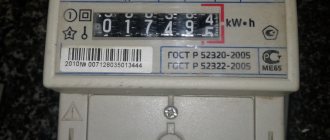
Taking readings
Electromechanical meters are equipped with a digital drum that displays electricity consumption in kilowatts. You can submit this data to the settlement service or make calculations yourself.
Depending on the model, 5 or 7 numbers appear on the reel display, with the last one separated from the rest by a comma and highlighted in color. When accounting, you do not need to count tenths and hundredths of kilowatts - only whole numbers. The resulting kilowatt consumption per month is multiplied by the cost of 1 kilowatt and the amount that must be paid for electricity is obtained.
What does the meter take into account?
Regardless of how the electricity meter is designed, it basically measures the power of the consumer, based on which the amount of energy consumed over a certain period of time is calculated. The resistance (load) indicator itself in AC networks can be active or reactive. And at the root of the sum of the squares of the values of both types of consumption (formula – P = √ ((UI cosθ) 2+ (UI sinθ) 2) gives the total load power of the circuit and taking into account reactive energy, energy circulates uselessly between connected network elements, the last factor arises in cases where the coil of a capacitor or transformer is connected to alternating current circuits.
Induction meters, by virtue of their design, are capable of detecting active load or simply reactive load, which was used by some unscrupulous consumers to distort readings in measuring devices of older models. The electronics works with both characteristics, calculating the total power using a certain formula, taking the current network load characteristics as a basis.
Installation of three-phase
There are five wires at the input of three-phase networks:
- 3 phases (“A”, “B”, “C.”);
- zero;
- Earth.
The terminals on the meter are located as follows:
- terminal 1 – for phase “A” input
- terminal 2 – for phase “A” output.
- terminal 3 – for phase “B” input.
- terminal 4 – for phase “B” output.
- terminal 5 – for phase “C” input.
- terminal 6 – for phase “C” output.
- terminal 7 – for zero input
- terminal 8 – for zero output.
The principle of connecting a three-phase meter is otherwise the same as a single-phase one. The “ground” input wire, if any, is connected directly to the corresponding terminal of the electrical panel.
Input wires in three-phase networks are usually multi-colored, like the terminals on the meter, which simplifies the connection process.
Please note: despite the different colored wires, you should check each phase with a multimeter.
The connection of such wires is carried out according to the instructions for the electric meter.
It is important not to confuse these terminals with the main ones. For any design of a two-tariff electric meter, they will be displayed in a separate row
Please note: before you begin installing an electric meter, you should carefully study the diagrams and documentation for it, since its characteristics may differ from the generally accepted ones.
You may also be interested in the article about Mercury two-tariff electricity meters.
Read a detailed article on how to connect a single-phase electricity meter here.
Design and operating principle
The device consists of three identical units (on the right), power circuits and a microcontroller. The measuring device is compatible with single-phase and three-phase AC circuits. Its design is presented:
- housing made of heat-resistant plastic or metal with a terminal block;
- display - LCD indicator, which displays data and time, or mechanical;
- power source for the electronic circuit;
- current transformer – performs the functions of a meter;
- a microcontroller that converts the input signal into electrical quantities;
- telemetric output for integration with ASKUE;
- clock – allows you to track real time and dates;
Appearance of an electronic electricity meter - supervisor - monitors input voltage fluctuations and sends a reset command to the microcontroller when the voltage turns off or on;
- control system;
- an optical port that allows you to take readings from the device.
The operating principle of a digital electricity meter is to directly measure voltage and current. It digitizes information, transmitting it to the indicator and storing it in memory. Pulses of input electronic solid-state elements are created under the influence of voltage current. The number of pulses depends on the activity of the energy.
Rules for legal and safe installation
Installing an electric meter is not our whim, but a requirement of the law and the electricity supplier.
Each electricity meter has a seal that is installed by the electricity supplier. It is impossible to replace the electric meter without damaging it. Therefore, you should notify your electricity supplier before replacing it.
Please note: before removing the electric meter, you need to rewrite its readings, which must be reported to the supplier.
For your own safety, all work on replacing the electric meter should be carried out only with a complete blackout, which can be done by turning off the corresponding machine on the external panel. This is usually located in the staircase entrance, or not far from a private house.
Electricity meter device
Recently, induction electricity meters have been replaced by electronic ones. In these meters, the counting mechanism is driven not by voltage and current coils, but by specialized electronics. In addition, the means of counting and displaying readings can be a microcontroller and a digital display, respectively. All this made it possible to reduce the overall dimensions of the devices, as well as reduce their cost.
Almost any electronic meter includes one or more specialized computing chips that perform basic conversion and measurement functions. The input of such a microcircuit receives information about voltage and current from the corresponding sensors in analog form. Inside the microcircuit, this information is digitized and converted in a certain way. As a result, pulse signals are generated at the output of the microcircuit, the frequency of which is proportional to the current power consumption of the load connected to the meter. The pulses are sent to the counting mechanism, which is an electromagnet coordinated with gears on wheels with numbers. In the case of more expensive meters with a digital display, an additional microcontroller is used. It connects to the above-mentioned microcircuit and to a digital display via a specific interface, accumulates the result of measuring electricity in non-volatile memory, and also provides additional functionality of the device.
Pros and cons of devices
The old-style disk electric meter has several advantages over new electronic meter models that are actively being introduced into residential buildings:
- have a high degree of reliability;
- simple design and principle of operation;
- the cost of an old-style electric meter is lower than an electronic one;
- indifferent to possible voltage drops in the electrical network;
- have a long service life.
If the accuracy class of an electric meter is low, the consumer can either overpay for electricity or underpay.
At the same time, electromechanical meters also have a number of disadvantages, which include:
- Low accuracy class for electrical energy metering, especially at low loads.
- There is only one tariff used to pay for electricity, while most electric companies provide different prices for electricity during the day and at night.
- The ability to stop disk rotation, and even rewind the indicators, which can be taken advantage of by unscrupulous users. Stopping the disk is also possible in case of failure.
All the disadvantages inherent in induction products are known to the manufacturing plants. They are constantly working to modernize and improve the quality of their products, increasing the accuracy class and service life. However, the design features do not allow all these useful necessary conditions to be fully implemented in the device. Therefore, induction devices are being replaced by more advanced, electronic ones.
Design and principle of operation
The design of the meter depends on the principle of its operation and the functions it performs. A single-phase induction meter is used in single-phase alternating networks and consists of the following parts:
- composite body;
- two windings: current and voltage;
- two magnetic cores: current windings and voltage windings;
- opposite poles;
- aluminum disk;
- worm type mechanism;
- counting mechanism;
- a permanent magnet used to brake the disk;
- axis on which the counting mechanism, worm gear and aluminum disk are mounted.
Schematic design of a single-phase induction-type electric meter
The principle of operation of the device is as follows. 2 electromagnets represent the measuring mechanism of the meter. They are located at an angle of 90° to each other. In the magnetic field of these electromagnets there is a disk made of aluminum. The meter is put into operation by connecting the current winding to the electrical receivers in series, and to the voltage receivers in parallel. When alternating current passes through the windings, magnetic fluxes of variable magnitude arise in the cores. They penetrate the disk, as a result of which they induce eddy currents. When the latter interact with magnetic fluxes, a force is created that rotates the disk. It, in turn, is connected to a counting mechanism that takes into account the rotational speed of the disk. The numbers located on the counting mechanism record the consumption of electrical energy.
As the load current increases, more torque is generated, which causes the disk to rotate faster.
The operating principle of three-phase induction meters is similar to the meter described above, with the only difference being that they are used in three-phase AC networks.
Front view of a three-phase induction electric meter with the cover removed
Side view with the rear housing of a three-phase induction meter removed
With the development of electronic technologies, electronic energy consumption meters appeared. Their operating principle is quite simple. A special converter converts input analog signals from current and voltage sensors into a digital pulse code. It is fed to a microcontroller, which records the amount of electricity consumed on the product display. Hence the main parts of an electronic meter are:
- protective casing;
- transformers measuring current and voltage;
- converter;
- microcontroller, which is the control body and transmits information to the display;
- terminal block for electrical connection. wires
The operation of single-phase and three-phase electronic meters is carried out according to the same laws, with the only difference being that in the 3-phase one the values of each of the three channels are summed.
Block diagram of the operation of a single-phase electronic type meter
From the diagram it can be seen that the current transformer is connected to the phase wire break, and the voltage transformer is connected to zero and phase. The current and voltage signals are converted into power and frequency in digital form using a converter; the microcontroller then controls the random access memory (RAM), an electronic relay and a display that displays digital information that records the electricity consumption of an object connected to the meter. RAM in some models can play the role of an information transmitter, which makes it possible to control the operation of the meter from a distance.
Electronic meters for measuring electricity consumption in three-phase circuits can operate in both three- and four-wire circuits. Devices store time-based information. Readings can be taken over a certain period of time and the following indicators can be recorded:
- active consumption;
- reactive consumption;
- effective values of voltage and current;
- frequency in each phase.
All this made it possible to create multi-tariff meters for calculating electricity consumption at different times of the day, by day of the week or by season.
How does an induction meter work?
The essence of the operation of induction electricity meters is based on the principle that a moving part is simultaneously affected by a rotating and braking torque. This moment is proportional to the accounting value, the braking moment is proportional to the speed of rotation of the moving part. An induction single-phase electricity meter consists of several elements:
- Voltage coils that are located on the magnetic circuit;
- Aluminum rotation disc;
- Transmission mechanism of the metering device;
- Current coils on the magnetic circuit;
- Permanent magnet.
The coil is made of wire with a large cross-section, which can withstand a large load. Coil turns are available in small quantities, usually 13-30 turns per coil. They are distributed in a uniform position on two magnetic cores, which have a U shape and are made of electrical steel. The core works to create a certain concentration of magnetic flux, which crosses the counting disk and rotates it.
The voltage winding is connected to the mains voltage phase and always has an operational state, along with the consumer, which is why it is called a parallel circuit. A voltage coil is required to produce a magnetic flux that will be proportional to the mains voltage. It has certain design differences from the current coil in that it has more turns, about 8000 - 12,000, and a small conductor cross-section of 0.1 - 0.15 mm2. In large numbers, the turns create a higher inductive reactance than the active resistance of the winding, which is quite important for complying with the 90° shift rule and makes it possible to reduce electricity consumption on a single-phase meter.
Electronic meters for electricity. The operating principle of an electronic electricity meter.
With the rapid development of electronic computing technology, electronic (digital) meters have replaced them. The operating principle of any electric meter is based on combining the instantaneous values of current and voltage consumed from the network for a certain unit of time for subsequent display on the counting device in the form of finished kilowatt-hours. The electronic meter consists of the main components:
- current and voltage sensors;
- power to pulse frequency converter (KR1095PP1);
- central microcontroller (control device -MC68NS05KJ1);
- read-only memory (ROM);
- liquid crystal display controller (ZhKI-K182SVG2);
Electrical signals from current and voltage sensors are sent to a power-frequency converter, which performs a multiplication operation to obtain the power consumed. The converter transmits the resulting power value in the form of a pulse to the input of the central microcontroller, which, in turn, sums the pulses over a certain time, obtaining kWh. The central microprocessor transmits data to the LCD microprocessor, which is ultimately displayed on the display.
An EEPROM memory device is used to save meter readings in the event of a power loss. If the meter suddenly loses power, then after turning it on, the microcontroller first retrieves the last stored value from the ROM and displays it on the display. After which it continues to count pulses from the converter, exchanging data with EEPROM, and increases the counter readings.
The presence of an external interface channel on an electronic meter using RS-485 as an example allows you to combine meters into groups and transfer all data to the electricity supply company, which makes it possible to turn off electricity to consumers in case of non-payment.
A measuring transformer (current transformer) or a shunt plate serves as a current sensor; voltage sensor - voltage sensor.
The three-phase electronic meter has the same design and has the functions of displaying active, reactive and total consumed electricity, etc.
Energy meter Energomera, appearance
In this article I will tell you and show in the photo how an electric meter works. For example, let's analyze (open) the Energomer TsE 6807 P
produced by the Stavropol concern "Energomera". What the counter looks like is in the photo on the left.
meter TsE6807P
- one of the simplest in design, the easier it will be to examine its structure.
By the way, several articles on electric meters have been published on the SamElectric.ru blog: - , - , - , - .
And if you are at all interested, subscribe to receive new articles and join the group on VK!
Electronic and hybrid meters
In electronic electricity meters, power consumption is calculated using a similar principle of multiplying current and voltage. But, unlike induction meters, where multiplication occurred due to the composition of electromagnetic fluxes of current and voltage coils, in electronic electricity meters signals from sensors are converted into pulses. These pulses are summed up in an electronic counting device or sent to an electromechanical drive of a digital drum (hybrid counter).
Hybrid electricity meter with electronic board and mechanical digital drum
An electronic electricity meter has current transformers in the power circuit and voltage sensors. From these sensors, the signals enter the current and voltage indicator converter, where pulses are generated with a frequency depending on the power taken into account by the meter. Counting pulses are sent to a microcontroller, which generates a stream of digital data that is displayed on the display, recorded in memory, and transmitted through communication ports.
Electronic meter board with sensors - built-in current transformers (CTs)
The counting pulse can be seen by the blinking LED on the electricity meter display. Next to the LED, the number of pulses per kilowatt hour for this meter is indicated. If there is a designation of 1000 imp/kWt, then one LED flash means a thousandth of one kilowatt hour of electricity. Sometimes users count flashes over a specific time if they have doubts about the accuracy of their meter.
Advantages of an electronic electricity meter
Thanks to the electronic device of the meter, it has many more capabilities and functions that cannot be implemented using a mechanical inductive electric meter:
- installation and reprogramming of several tariff time zones (example - two-tariff electricity meters);
- high accuracy class;
- small dimensions make it possible to mount on a DIN rail;
Modular three-phase electronic electricity meter mounted on a DIN rail - the ability to fully account for consumed electricity (active and reactive components);
- measurement and storage of data on power quality (voltage surges, peak loads, frequency changes);
- storage of counter indicators for previous periods;
- the possibility of remote transmission of meter readings, including in automated metering systems for electrical energy consumption; Thanks to built-in memory and communication ports, modern electricity meters can store and remotely transmit readings
- detection of unauthorized access to the housing, attempts to reprogram, or exposure to magnetic fields or electromagnetic radiation;
- the possibility of reverse metering when a private individual or company produces electricity supplied to the network;
- recording and prohibiting electricity consumption when various devices and connections are detected in the network intended for theft of electricity;
- low own electricity consumption.
Electronic meter in a distribution board
Most of the above functions are useless for the average user, and make it much more difficult for fraudsters to steal electricity. But for electricity suppliers, metering using electronic electricity meters allows them to avoid significant losses and theft of electricity, as well as introduce differential tariffs and use remote data reception.
Disadvantages of an electronic meter
Since electronic meters have a smaller error, they keep a much more accurate accounting of electricity than induction electricity meters, which count kilowatt-hours for the benefit of the consumer. Therefore, users who have switched to electronic meters have complaints and suspicions about the deliberate incorrect operation of their electricity meters, because previously they had to pay less.
From the point of view of the electricity consumer, high accuracy and small error are disadvantages, although the electronic meter shows the real amount of electricity
The design of an electronic meter is much more complex than an induction meter, so it is less reliable , and there are many complaints from users who are forced to change electric meters at their own expense, which burn out for various reasons. The large number of semiconductor elements in an electronic meter makes it vulnerable to various types of overvoltages, because mains voltage is used to power the circuit.
The complex electronic board of the meter is vulnerable to voltage surges
The complex design of the electronic meter and a large number of sometimes unnecessary functions make such an electric meter more expensive than a conventional induction meter. At the same time, in the event of a breakdown, electronic meters are practically not repaired, since they must be sent to the manufacturer, where a labor-intensive process must be carried out to check each component of the electric meter to identify faults or deviations. Rigorous testing followed by recertification is very expensive, so electronic meters cannot be repaired.
Outdoor electricity meters for private homes and cottages
LEMZ TsE-2726-SOLO-G05
The device is designed for outdoor operation in the temperature range from –15 to +40°C. The contact row is also located under a sealed removable cover. The device has a reverse stopper and protection against unauthorized access.
Specifications:
- Network type: single-phase
- Number of tariffs: 1
- Accuracy class: 1
- Operating principle: electromechanics
- Cost: 900 – 950 rub.
- Disadvantages: none found
Enron TOPAZ 103-5(60)1-ShR1E-O4
The Topaz two-tariff electricity meter is designed to operate in a network with a current of up to 50 A and the possibility of differentiated metering at three tariffs. The interface type has a special designation RS 485, which indicates the compatibility of its functionality with AIIS KUE (Automated Commercial Electricity Metering System) systems. The front instrument panel is hermetically sealed with a transparent plastic cover. There are grooves on the back of the housing for easy installation of the meter on a DIN rail.
Specifications:
- Network type: single-phase
- Number of tariffs: 2
- Accuracy class: 1
- Operating principle: electronic
- Cost: 1200 – 1300 rubles
- Disadvantages: fragile body
The Taipit brand is a St. Petersburg concern with many production branches in the Russian Federation. Its products are also supplied abroad. Model MT-324-1A is a new development. The device is designed to operate in a single-phase network with a current of up to 50 A. The electronics are reliably protected from external electromagnetic influences and adverse weather conditions. This is an excellent solution for outdoor installation in a private home.
Specifications:
- Network type: single-phase
- Number of tariffs: 4
- Accuracy class: 1
- Operating principle: electronic
- Cost: 3229 – 3400 rub.
- Disadvantages: none found
Mercury 231ART 01-Ш
The best two-tariff meter is Mercury 231ART 01-Ш. It is characterized by high measurement accuracy. If a malfunction occurs, the meter system automatically starts a self-diagnosis mode, and using error codes you can easily determine the cause of the failure and quickly restore functionality.
Specifications:
- Network type: three-phase
- Number of tariffs: 2
- Accuracy class: 1
- Operating principle: electronic
- Cost: 2450 – 2800 rub.
- Disadvantages: none found
ISKRA ME382-D2 10(100)A
The ISKRA ME382-D2 electric meter is designed and manufactured in accordance with international standards ISO-9001 and ISO-14001. The electric meter provides accounting for electricity parameters much better than required by the European standard IEC-62053-21.
Active energy is measured in 2 directions, reactive energy is measured in 2 directions plus 4 quadrants. The meter measures total energy and power, as well as instantaneous values of phase voltages, current, frequency and power factor. The functionality of the device includes recording the amounts of received/given energy and power.
The meter has the ability to use a tariff schedule to register active energy and maximum power (8 tariffs, 12 seasonal and 12 weekly programs, 16 masks, 16 modes). The accumulated data will be transmitted over separate channels via SM/GPRS modem or M-Bus/DLMS/IDIS protocol.
This brand of meters is intended for both domestic and industrial use within the temperature range from –40°C to +70°C. To protect the device and ensure proper operation there is a foil screen and an emergency power contact breaker. The device is absolutely reliable, as it is made with protection against dust, water and dirt according to class IP54. It is possible to install this meter outdoors. The ME382 is perfect for large homes with heavy use of electrical appliances.
Specifications:
- Network type: three-phase
- Number of tariffs: 8
- Accuracy class: 1
- Operating principle: electronic
- Cost: 25,000 – 27,700 rubles
- Disadvantages: complex functionality, high price
Iek CCE-3C1-3-01-3
Three-phase economical electric. The Star model counter has an analog metering scale and LED indication of operating modes. There are grooves on the back panel for mounting the device on a dinrail.
Specifications:
- Network type: three-phase
- Number of tariffs: 1
- Accuracy class: 1
- Operating principle: electromechanical
- Cost: 380 – 650 rub.
- Disadvantages: none found
The installation location affects the meter error!
Another factor influencing the measurement of power consumption is the installation location of the meter. Electronic electricity meters (single-phase or three-phase, single-tariff or two-tariff) are now placed on the facades of houses or directly on power line supports, that is, on the boundaries of the balance sheet, at the request of the electricity supply organization. They explain to us that this is necessary for the convenience of controllers writing off readings and to prevent the theft of electricity.
However, the fact is hushed up that at low or high temperatures they have a positive error, in other words, they generate extra kilowatts. Induction meters are intended for installation indoors, but they can be installed outdoors with additional heating.
Research conducted by Ph.D. Gurtsevich, leading researcher at RUE "BelTEI" in Minsk, the errors of electronic electricity meters of various brands with accuracy classes 1 and 2 are given in Table 1.
Table 1. Limits of permissible additional error for meters of classes 1 and 2
Abbreviations in the table:
- NV/TV, respectively, direct and transformer connection of the meter;
- STC – average temperature coefficient, % / 1 °C;
- when U changes outside the specified limits, the error may increase by 3 times.
- KM - power factor.
Load current In in the range from 0.1 Ib (Ib is the base current, i.e. the current value that is the initial value for establishing the requirements for a meter with direct connection) to Imax (Imax is the highest current value at which the meter meets the established accuracy requirements ) or from 0.05 In (In is the current value that is the initial value for establishing the requirements for a meter operating from a transformer) to Imax - the established measurement range - with a power factor equal to 1 (including in the case of multi-phase meters - with symmetrical loads ), when testing the meter under normal conditions (taking into account permissible deviations from the nominal values) established in the standards defining particular requirements.
Table 2. Normal conditions (NU) for checking the meter for accuracy
When checking an electronic electricity meter for accuracy under normal conditions (Table 2), errors that arise in the meter under the influence of the values in the first column are allowed.
When the influencing quantities change (Table 1), when the current flows through the electric meter within the indicated limits with the specified power factor, additional errors arise in the meter, which, when summed up, are added to the main ones, thereby distorting the readings of the meter, both positive and negative side.
Induction meters
Internal structure of an induction meter:
The basis for the functionality of these meters is the physical law of magnetic induction. In the design, to create the effect, two electromagnets of different shapes and orientations relative to each other are used for each phase of the consumer. One of them is connected directly to the mains power, and the second to the load line break. The fields they generate initiate the appearance of eddy currents on a disk of conductive metal, due to which the latter is set in motion, making revolutions around its axis. Moreover, the stronger the load on the line to which one of the field generators is connected, the more electrons accumulate on the moving element, which is why it rotates faster. In order to limit the moment of movement - so that the speed does not become equal to that used in the electric motor - a permanent magnet installed near the surface of the aluminum disk is used.
Classic scheme:
The above image shows the magnetic fields circulating during the operation of the device. They are designated ФI, ФU1 and ФU2. The remaining elements of the diagram are indicated by numbers. Under number 1 with a winding marked 2 is the guidance electromagnet. The armature of the second is marked 3 with power line 4 connected to the load. An aluminum conductive disk is attached to 6, and 7 is the axis on which it is located. 8 - gearbox that transmits torque to the counting mechanism 9.
The design of an electric meter of a similar design is so simple that induction electricity meters were manufactured and used back in the 19th century.
Varieties of connection schemes
The device is intended for installation in power lines with a current of up to 100 A. This way you can reduce the load on equipment compatible with metering devices up to 60 kW. A feature of direct meters is the impossibility of connecting contacts to large cross-section conductors. You should connect like this:
- The insulating layer of 5 mm is removed from the cable. Oxidation is removed using a solvent.
- The conductors are connected to a three-pole circuit breaker installed for the meter. This is done to protect it from a short circuit on the power line.
- The terminal section of the device contains contacts.
- The odd numbered ones are connected to 3 phase wires from the auto power switch.
- Input and output neutrals are connected to terminals No. 7 and No. 8.
- After installing the accounting module, a machine similar to the introductory product is installed.
- The switch is connected to even-numbered terminals.
- The equipment is divided into groups and automatic machines are installed on each phase (for networks with a voltage of 220 V).
We invite you to familiarize yourself with How an electricity meter works
Features of the connection diagram can be seen on the terminal block cover.
A semi-indirect electricity meter is connected to metering transformers. You need to calculate the amount of energy used based on the conversion index. To do this, use one of the schemes:
- Ten-wire. You will need 11 wires that connect from right to left. Phase A is connected to the first 3, phase B to the second 3. Phase C is added to cables No. 7-9, and neutral to the tenth. The three-phase power supply must be connected using test blocks.
- Star. The use of the circuit allows you to reduce the number of conductors. First, the first unipolar outputs of the secondary winding are collected at one common point. The next 3 points from the outputs are sent to the counter. The current windings are connected.
Ten-wire star
Semi-indirect models can also be thrown by coupling the current circuit with the voltage circuit.
Connection diagram of a three-element meter to a three-wire line - two current transformers, three voltage transformers
With minimal energy consumption, indirect connection is relevant. Since increased current passes through the metering products, a separate transformer is required. The converter breaks the current winding when connected. The scheme is implemented sequentially:
- Selection of materials for the primary and secondary circuits. For the primary, you will need a thick conductor passed through the center of the transformer. The secondary is wound from thin wire.
- Transformers are thrown onto each of the phases and attached to the rear wall of the distribution cabinet.
- The ends of the primary wires are connected to the machine at the input.
- The second part of the primary circuit contacts is connected with separate conductors with a cross-section of 1.5 mm2 to terminals No. 2, 5 and 8.
- The secondary coil is connected with similar cables to the terminals of the metering device - 1 to 3, 4, and 6 and 7 to 9.
- A neutral wire is connected to terminal blocks No. 10 and 11.
How to properly replace an electricity meter in an apartment
Devices of the modern generation are more advanced than older models, because they process a fairly large amount of electrical energy, eliminating the occurrence of serious problems:
- changes;
- failures;
- short circuits and fires.
Requirements of Decree 442 on the replacement of electricity meters
According to the updated resolution No. 442, the rules for controlling the market for the retail sale of electrical energy have been changed. The document stipulates that the transmission of readings from electricity meters used by citizens of the Russian Federation should be carried out using exclusively electrical devices, and the minimum acceptable accuracy class of devices is 2.0.
Modern devices have a fairly high accuracy class
After decree No. 442 was issued, the service life of electric meters corresponds to the duration of the inspection interval - 6 years. This means that an inappropriate device can be used until the first inspection by the authorities, then it must be replaced. Today, the production of devices with an accuracy class below 2.0 is stopped. Repairs are also not allowed.
On the one hand, the procedure for changing metering equipment is designed to increase the safety of electricity operation, on the other hand, the question arises at whose expense the replacement of electric meters is carried out. Subject to Article 221, payment for replacement is made by the owner of the residential premises.
Payment for replacing the electric meter is made by the owner of the apartment
There are circumstances in which payment is made by the municipal service. This applies to those contracts received when installing electricity meters in an apartment where there is a corresponding note, otherwise the owner independently covers all costs.
Service life of an electric meter in an apartment
The operational life of any device is specified in the technical data sheet. During this period, provided that the settings are correct and there are no violations of operating rules, the device keeps records of consumed energy as accurately as possible. Therefore, all data obtained during this period can be considered reliable.
To check the service life of the device, just look at the technical data sheet. There is a mark indicating the time of the first meter check performed on the premises of the manufacturing plant. Most often, equipment is considered suitable for 25-30 years, after which it is necessary to replace the device.
The meter must match the power of the current that passes in the electrical networks
The timing for replacing electric meters in apartments is established after a scheduled check of the device:
If there is a meter in the apartment with an accuracy class of 2.0 or 1.0, then scheduled verification of electricity meters is performed every 16 years. During the control process, errors and any violations may be detected. Then the metrological service will recommend replacing the equipment. The average service life of such devices is 32 years. If there is a device with an accuracy class of 2.5, the homeowner is obliged to replace the accounting equipment after its service life expires according to the technical passport. A signal for replacement can also be the detection of errors in the operation of the device.
Replacement of electricity monitoring devices is carried out by specialists
How much does it cost to replace electric meters in apartments?
All procedures for installing accounting equipment must be carried out by highly professional specialists. Working with electricity is extremely difficult and dangerous. The electrician must have the right to unseal and seal the meter. It is not prohibited to use the services of private companies, however, you should find out in advance whether the master has the appropriate permission. Otherwise, such actions may be illegal.
The cost of single-phase multi-tariff electricity meters Mercury is 1280-1400 rubles. The price of similar single-tariff devices is in the range of 670-700 rubles. Added to this is the cost of maintenance for dismantling the old device, installing new equipment and connecting it.
Installation of electricity meters in an apartment: service prices:
| Name of service | price, rub. |
| Installation of single-phase single-tariff equipment | 1500-2000 |
| Installation of single-phase multi-tariff equipment | 1500-2000 |
| Dismantling the device | 500 |
| Installation of three-phase equipment with direct connection | 2500-3000 |
| Installation/replacement of equipment on a support/pole | 5000-7000 |
| Dismantling the device on a support/pole | 35000 |
Do I need to replace the meters with new ones?
If you have an old induction meter installed, do not rush to replace it with a new one. It is quite possible that it will serve for a long time, until the end of the service life indicated in the passport, which is almost 20 years. However, in some cases they may be forced to make a replacement and you will be required to purchase a new meter.
Electricity meters must be replaced in the following cases:
- Work is underway to routinely update the electrical network with the replacement of all meters.
- The meter is faulty.
- The service life of the device has expired according to the technical data sheet.